
LEC120-12
INPUT:
100 – 240 VAC, 1.5 - 0.75 A, 50 - 60 Hz (UL certified) or 120 - 370 VDC, 1.5 – 0.75 A
OUTPUT:
12 VDC, 10 A
LEC120-24
INPUT:
100 – 240 VAC, 1.5 - 0.75 A, 50 - 60 Hz (UL certified) or 120 - 370 VDC, 1.5 – 0.75 A
OUTPUT:
24 VDC, 5 A
LEC120-48
INPUT:
100 – 240 VAC, 1.5 - 0.75 A, 50 - 60 Hz (UL certified) or 120 - 370 VDC, 1.5 – 0.75 A
OUTPUT:
48 VDC, 2.5 A
READ THIS CAREFULLY BEFORE
INSTALLATION!
VOR DER INSTALLATION BITTE FOLGENDE
SICHERHEITSHINWEISE BEACHTEN!
LEGGERE ATTENTAMENTE PRIMA
DELL’INSTALLAZIONE!
A LIRE ATTENTIVEMENT AVANT
L’INSTALLATION!
Before operating, read this document
thoroughly and retain it for future reference.
Non-respect of these instructions may reduce
performances and safety of the devices and
cause danger for people and property
Lesen Sie dieses Dokument vor der Inbetriebnahme
sorgfältig durch und bewahren Sie es zum späteren
Nachschlagen auf. Die Nichtbeachtung dieser
Anweisungen kann die Funktion und Sicherheit der
Geräte beeinträchtigen und birgt Gefahren für
Personen und Eigentum.Haftung für die Folgen, die
sich aus dem Einsatz dieses Gerätes ergeben.
Prima dell’installazione, leggere attentamente
questo documento istruzioni e conservarle per
future consultazioni. L’inosservanza delle presenti
istruzioni può compromettere le caratteristiche e
la sicurezza dell’apparecchio e causare pericolo
per le persone e le cose.
Lire ces instructions avant l'installation, conserver
ce manuel pour référence future. Défaut de se
conformer à ces instructions peut affecter les
caractéristiques et la sécurité du dispositif, et
causer du danger aux personnes ou aux biens
CAUTION
ACHTUNG
ATTENZIONE
AVVERTISSEMENT
RISK OF BURNS, EXPLOSION, FIRE,
ELECTRICAL SHOCK, PERSONAL INJURY.
1. Do not use this power supply without proper
grounding (protective grounding), use the
wiring terminals on the input components
instead of the screws on the shell for
grounding;
2. Before performing operations on the
equipment, turn off the power supply to
provide protection to avoid accidentally re-
energizing;
3. Comply with all local and national
regulations to ensure correct wiring;
4. Do not modify or repair this product;
5.Do not open the unit as high voltages are
present inside;
6. Take care to prevent any foreign matter from
entering the shell;
7. Do not use this product in humid places or
areas where moisture or condensation may
occur;
8. When the power is turned on and just after it
is turned off, do not touch it. The hot surface
may cause burns;
Gefahr von Stromschlag, Feuer, Körperverletzung
oder Tod:
1. Verwenden Sie dieses Netzteil nicht ohne
ordnungsgemäße Erdung (Schutzerdung).
Verwenden Sie zur Erdung die Anschlussklemmen
an den Eingangskomponenten anstelle der
Schrauben am Gehäuse;
2. Schalten Sie vor dem Ausführen von Arbeiten am
Gerät die Stromversorgung aus, um ein
versehentliches Wiedereinschalten zu vermeiden.
3. Beachten Sie alle lokalen und nationalen
Vorschriften, um eine korrekte Verdrahtung zu
gewährleisten;
4. Modifizieren oder reparieren Sie dieses Produkt
nicht;
5. Öffnen Sie das Gerät nicht, da im Inneren hohe
Spannungen anliegen;
6. Achten Sie darauf, dass keine Fremdkörper in die
Schale gelangen;
7. Verwenden Sie dieses Produkt nicht an feuchten
Orten oder in Bereichen, in denen Feuchtigkeit oder
Kondensation auftreten kann;
8. Berühren Sie das Gerät beim Einschalten und kurz
nach dem Ausschalten nicht, da die heiße
Oberfläche Verbrennungen verursachen kann.
Rischio di scosse elettriche, incendi, lesioni
personali o morte:
1. Non utilizzare questo alimentatore senza
un'adeguata messa a terra (messa a terra di
protezione), utilizzare i terminali di cablaggio sui
componenti di ingresso invece delle viti sul guscio
per la messa a terra;
2. Prima di eseguire operazioni
sull'apparecchiatura, togliere l'alimentazione per
fornire protezione per evitare la riaccensione
accidentale;
3. Osservare tutte le normative locali e nazionali
per garantire un cablaggio corretto;
4. Non modificare o riparare questo prodotto;
5.Non aprire il dispositivo poiché all'interno sono
presenti alte tensioni
6. Fare attenzione ad evitare che corpi estranei
entrino nel guscio;
7. Non utilizzare questo prodotto in luoghi umidi o
aree in cui potrebbe verificarsi umidità o
condensa;
8. Quando l'apparecchio è acceso e subito dopo
averlo spento, non toccarlo.La superficie calda
può causare ustioni..
Risque de choc électrique, d’incendie, de
blessures corporelles ou de décès:
1. N'utilisez pas cette alimentation sans mise à la
terre appropriée (mise à la terre de protection),
utilisez les bornes de câblage sur les composants
d'entrée au lieu des vis sur la coque pour la mise
à la terre ;
2. Avant d'effectuer des opérations sur
l'équipement, coupez l'alimentation électrique
pour assurer une protection afin d'éviter une
remise sous tension accidentelle ;
3. Respectez toutes les réglementations locales
et nationales pour garantir un câblage correct ;
4. Ne modifiez ni ne réparez ce produit ;
5.N'ouvrez pas l'appareil car il y a de hautes
tensions à l'intérieur
6. Prendre soin d'éviter que des corps étrangers
ne pénètrent dans la coque ;
7. N'utilisez pas ce produit dans des endroits
humides ou des zones où de l'humidité ou de la
condensation peuvent se produire ;
8. Lorsque l'appareil est allumé et juste après
l'avoir éteint, ne le touchez pas. La surface
chaude peut provoquer des brûlures.
INTENDED USE
BESTIMMUNGSGEMÄßER BETRIEB
USO PREVISTO
UTILISATION
These are designed to be mounted on DIN rails
and installed in protective enclosures. They are
suitable for general purposes, such as
industrial control, communications, and
instrumentation equipment.
Do not use these devices in applications where
malfunctions may cause personal injury or
death.
Diese sind für die Montage auf DIN-Schienen und
den Einbau in Schutzgehäuse vorgesehen. Sie
eignen sich für allgemeine Zwecke, wie z. B.
industrielle Steuerungs-, Kommunikations- und
Instrumentierungsausrüstung.
Verwenden Sie diese Geräte nicht in Anwendungen,
bei denen Fehlfunktionen zu Verletzungen oder zum
Tod führen können.
Questi sono progettati per essere montati su
guide DIN e installati in custodie protettive. Sono
adatti per scopi generali, come controllo
industriale, comunicazioni e apparecchiature di
strumentazione.
Non utilizzare questi dispositivi in applicazioni in
cui malfunzionamenti possono causare lesioni
personali o morte.
Ceux-ci sont conçus pour être montés sur des
rails DIN et installés dans des boîtiers de
protection. Ils conviennent à des usages
généraux, tels que les équipements de contrôle
industriel, de communication et d'instrumentation.
N'utilisez pas ces appareils dans des applications
où des dysfonctionnements peuvent causer des
blessures ou la mort.
ENVIRONMENTAL CHARACTERISTICS
UMGEBUNGSBEDINGUNGEN
CARATTERISTICHE AMBIENTALI
CARACTÉRISTIQUES ENVIRONMENTALES
Installation in a Pollution Degree 2
environment.
Do not use in wet area or subject to moisture.
Carefully recycle the product and related
batteries according to local regulations.
Installation in einer Umgebung mit
Verschmutzungsgrad 2.
Nicht in nassen Bereichen oder unter Feuchtigkeit
verwenden.
Das Gerät und die zugehörigen Batterien sind
entsprechend den lokalen Vorschriften zu recyceln
bzw. zu entsorgen.
Usare in ambienti con Grado di Inquinamento 2.
Non far funzionare l'apparecchio in un ambiente
umido o soggetto a formazione di condensa.
Riciclare il prodotto e le batterie collegate, nel
rispetto delle normative locali vigenti.
Utiliser les produits dans des environnements
avec degré de pollution 2.
Ne pas employer l'appareil dans un
environnement humide ou soumis à la
condensation. Recycler les produits et les
batteries, conformément à la réglementation
locale.

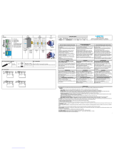
LEC120 Series
2
USER INSTRUCTIONS
1) DESCRIPTION
DIN rail-mounted main switching power supply, with 85 - 264 VAC (120 - 370 VDC) input, suitable for single-phase power lines and DC lines.
2) INSTALLATION
Use DIN-rails according to EN 60715. Installation should be made vertically (see Fig. 4). For better device stability fix the rail to the wall close to the point where the
device is to be mounted. In order to guarantee sufficient convection, we recommend observing a minimum distance to other modules (see Fig. 3).
The product has over-temperature protection;restricted airflow will cause local temperatures to be too high, which may trigger the over-temperature protection to
restart after cooling;
To get normal operation reduce the temperature of the air surrounding the power supply, increase the ventilation or reduce the load (see Fig. 8)
3) CONNECTIONS
The device is equipped with screw terminal blocks. To avoid sparks, do not connect or disconnect the connectors before having previously turned-off input power and
waited for internal capacitors discharge (minimum 1 minute)
In order to comply with UL certification,
When the ambient temperature is ≤ 60°C, use a copper wire with a specification of ≥ 90°C;
When the ambient temperature is > 60°C and ≤ 85°C, use a copper wire with a specification of ≥ 105°C;
Only use wires with a minimum insulation strength of 300 V (input) and 60 V (output).
4) INPUT PROTECTION
The device input is provided with varistors against overvoltage. Input is provided with internal fuses 4 AT / 250 VAC, thus an external short circuit / overcurrent
protection must be provided by the end user (see Fig. 6).
For operation on a single-phase system, a protection fuse on the phase must be provided.
Surge protection: it is strongly recommended to provide external surge arresters (SPD) according to local regulations.
5) AC INPUT CONNECTION
The device can be connected to single phase AC line with rated Vin 100 - 240 VAC (see Fig. 7). Please connect the PE first.
6) DC INPUT CONNECTION
Connect L terminal to (+) positive pole, N terminal to (-) negative pole and PE terminal to GND. Rated voltage 120 – 370 VDC. The device is also suitable for
photovoltaic or wind turbine applications (see Fig. 7).
7) OUTPUT CONNECTION
Vout can be adjusted with a potentiometer to a wide range (see Fig. 1)
Check Vout before connecting the power supply to the load. With output voltage set to the max. value, the continuous [current x voltage] must not exceed the
nominal power.
8) OUTPUT PROTECTION
The device is protected against overload (OL) / short circuit (SC) / overvoltage (OV) / overtemperature (OT).
Overload (OL) enters hiccup mode 1:
When the output power is 105%~150% of the rated output power, the output voltage is the nominal voltage, and the output of the product will be turned off after keeping it
constant for 3 seconds, and the output will restart after 10s, and the power will start to turn on/off Cycle hiccup mode until the abnormality is eliminated
Overload (OL) enters hiccup mode 2:
When the output power is 150%~200% of the rated output power, the output voltage begins to drop and remains constant. The output current depends on the value of the
output load impedance; the output voltage remains constant and shuts down after working for 1 second. Cut off the output, the output will restart after 10 s, and the power
will start on/off cycle hiccup mode until the abnormality is eliminated
Overload (OL) enters constant current (CC) hiccup mode:
When the output power is greater than 200% of the rated output power, the output voltage drops and depends on the value of the impedance of the faulty load circuit; the
output current is kept constant for 1s and then the product output is turned off, after 10s The output restarts, and the power supply starts to start the on/off cycle hiccup
mode until the abnormality is eliminated.
Short circuit (SC) enters constant current (CC) hiccup mode:
When the output load is short-circuited, the output voltage is close to 0V, the output current is constant, the device can provide ≥ 200% of the rated output current, and
the power supply keeps the output current constant for 1s and then shuts off the product output After 10 s, the output restarts, and then the device starts the on/off cycle
hiccup mode until the abnormality is eliminated.
Output OV circuit protection
:
The output is protected against potential OV. The protection phenomenon is that the output voltage is shut down, and the input restart is required to resume normal
operation.
The overvoltage protection point depends on the product model,
12 V: overvoltage protection point ≤ 18 V;
24 V: overvoltage protection point ≤ 35 V;
48 V: overvoltage protection point ≤ 60 V
OT protection:
It turns off the device if the internal temperature exceeds a safe limit. The device restarts automatically after cooling down. To recover to normal operation, reduce air
temperature surrounding the power supply, increase cooling or reduce load
9) FEEDING DC MOTORS
It is possible to feed DC motors considering that when a motor starts-up under effort its consumption is much higher than the nominal current and it can trigger
overcurrent protection (see accessory device).
NOTE: motors can generate high conducted noise on the DC line. Therefore, it is not recommended to feed on the same line motors and equipment sensitive to noise.
10) OPERATION WITH BATTERY
When a battery is connected in parallel to the Output for backup purposes (see accessory device).

3
INSTALLATION INSTRUCTION
Manufacturer
Bel Fuse Inc.
206 Van Vorst St.
Jersey City
NJ 07302, USA
Asia-Pacific
+86 755 2988 5888
Europe, Middle East
+353 61 49 8941
North America
+1 866 513 2839
© 2023 Bel Fuse Inc.
BCM.20049_B
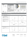
FIG. 1 - CONNECTIONS
FIG. 2 - DIMENSIONS
FIG. 3 - DISTANCES
* Pin 7 and the grounding screw (at the bottom) are
interconnected. Either Pin 7 or the grounding screw
need to be connected to earth.
Dimension
W
D
H
mm (in)
32 (1.26)
110 (4.331)
124 (4.882)
Distance
A
B
mm (in)
15 (0.8)
50 (2.0)
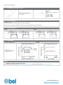
FIG. 4 - MOUNTING / DISMOUNTING INSTRUCTIONS
For DIN rail fastening according to IEC 60715 TH35-7.5(-15)
Mounting as shown in figure, with input terminals on lower side, with suitable cooling and maintaining a proper distance between adjacent devices as specified in the
Installation Instruction of each family.
MOUNTING:
1. Set the top of the power supply (A) on the
top of the DIN rail (B) to latch.
Press the bottom of the power supply (D)
against the rail to lock it in the position on
the rail (C).
2. Correctly installed power supply (vertically).
3. Insert the copper wires into the top and
bottom terminals and tighten them with a
screwdriver.
4. Adjust the output voltage with a suitable tool
according to adjustment range in the
selection guide.
1
2
3
4
DISMOUNTING:
5. Insert the screwdriver into the slide clamp
lever (E) and pull it down.
6. Tilt the power supply upwards to unhook it
from the rail.
5
6

LEC120 Series
4
FIG. 5 - RECOMMENDED CONNECTING CABLE
Recommended Tightening torque
0.79 ± 0.079 Nm
Wire range:
Input:
26 – 10 AWG (12 – 10 AWG for Pin7)
Output:
12 V: 16 – 10 AWG
24 V: 20 – 10 AWG
48 V: 22 – 10 AWG
DC OK: 24 – 16 AWG
FIG. 6 - INPUT PROTECTION
Fuse MCB 4 A C curve.
For USA and Canada, use the fuse type closest to the European equivalent type.
Surge protection: it is strongly recommended to provide external surge arresters (SPD) according to local regulations.
FIG. 7 - INPUT CONNECTIONS
AC LINE
DC LINE
FIG. 8 - ENVIRONMENT
OPERATING TEMPERATURE
DERATING
- 40°C to + 70°C
20 - 95% r.H. non condensing
UL Certified up to 70°C
NOTES:
▪ Specifications are subject to change without prior notice.
▪ Please refer to the latest version of the Datasheet and Installation Instruction for each product by visiting
belfuse.com/power-solutions
-
 1
1
-
 2
2
-
 3
3
-
 4
4


in altre lingue
- English: BEL LEC120 Installation guide
- français: BEL LEC120 Guide d'installation
Documenti correlati
-
BEL LEC240 Guida d'installazione
-
-
-
-
-
-
-
-
-
Altri documenti
-
 nextys NCU120 series Manuale utente
-
 Rockwell Automation 1606-xlp15 Manuale utente
-
Eurotherm 2500P - 2A5 Manuale del proprietario
-
-
 Rockwell Automation 1606-xlp15 Manuale utente
-
Puls QS10.DNET Manuale utente
-
Redlion MiniLine PSDR030W Manuale utente
-
 Rockwell Automation 1606-XLEDNET3 Manuale utente


