
CAME S.p.A.
Via Martiri Della Libertà, 15
31030 - Dosson di Casier
Treviso - Italy
tel. (+39) 0422 4940
fax. (+39) 0422 4941
XAS/301.01
XAS/301.01
B IN B OUT
XA/301LR
XAS/301.01
B IN B OUT
VSE/301
B OUT
A
B IN
M2
M1
SW10
SW10
LVC01
DVC01
A
B
C
D
E
F
G
A+B+C+D+E+F+G:
1.000 m max.
A
B
C
D
E
F
G
XAS/301.01
B IN B OUT
A
B
C
D
E
F
G
A+B+C+D+E+F+G:
1.000 m max.
A+B+C+D+E+F+G:
1.000 m max.
250 m max. 250 m max. 250 m max.
750 m max.
A
B
C
D
E
F
G
A+B+C+D+E+F+G:
600 m max.
A
B
C
D
E
F
G
A
B
C
D
E
F
G
A+B+C+D+E+F+G:
1.000 m max.
A+B+C+D+E+F+G:
1.000 m max.
100 m max. 250 m max. 250 m max.
600 m max.
LVC01
DVC01
11
22
XAS/301.01
B IN B OUT
XAS/301.01
B IN B OUT
XAS/301.01
B IN B OUT
SW10
SW10
SW10
SW10
VA/08
VA/01
XA/301LR
1
VA/08
VA/01
XAS/301.01
B IN B OUT
2
XAS/301.01
B IN B OUT
1
XAS/301.01
B IN B OUT
3
XAS/301.01
B IN B OUT
4
XAS/301.01
B IN B OUT
(25)
12
OUT
34
IN
SW0 SW2
SW4
SW3
XDV/304
1
34
IN
SW0
XDV/304
SW3 SW4
SW2
2
OUT
XDV/304
XAS/301.01
B IN B OUT
XAS/301.01
B IN B OUT
50
(25)
50
VA/01
SW10
SW10
SW10
SW10
SW10
SW10
SW10
LVC01
DVC01
VA/08
VA/01
LVC01
DVC01
VA/01
VA/01
VA/01
VA/01
VA/01
XAS/301.01
B IN B OUT
SW10
VA/01
DC/01
XAS/301.01
B IN B OUT
SW10
LC/01
LVC/01
VAS/101
1
XAS/301.01
B IN B OUT
SW10
VA/01
DVC/01
12
OUT
34
IN
SW0 SW2
SW4
SW3
XDV/304
1
XAS/301.01
B IN B OUT
(25)
50
SW10
VA/08
VA/01
DVC/08
SW1
SW2 SW4
SW3
M1
M3
M2
B3
+
-
B4
B1
B2
+
-
B OUT
+
-
M3 SW5
B IN
+
-
XAS/301.01
B IN B OUT
SW10
XDV/304A
XAS/301.01
B IN B OUT
VA/01
SW10
LVC01
DVC01
SW8
SW9
SW7
P6
P5
B OUT
M1
M3
M2
SW6
CN1
DL2
DL5 DL3
DL1
SW1
SW2
SW3
>250 m
<250 m
SW4
SW5
B IN
1
3
43,5
45
7,5 57
140
106
64,5
140
145
A B
C
D
FA01539M4A - 12/2021
FA01539M4A
IT
Italiano
EN
English
FR
Français
RU
Pусский
ITALIANO
ISTRUZIONI PER L’INSTALLATORE
Attenzione. Prima di procedere all’installazione
dell’apparecchio leggere attentamente le
“AVVERTENZE PER L’INSTALLAZIONE” contenute nella
confezione.
Descrizione
Dispositivo di ripetizione audio, video e dati per linee principali
X2 e X1, in grado di alimentare i derivati interni direttamente
dal BUS.
Permette l’estensione del sistema 300, X2 e X1 in termini di
distanze e quantità di derivati interni.
L’apparecchio è protetto elettronicamente contro sovraccarichi
e cortocircuiti.
Funzioni principali
- Collegamento di max. 200 citofoni.
- Collegamento di max. 100 videocitofoni dei quali solo 1
attivo.
- Collegamento di 2 amplificatori XDV/300A in impianti X1.
- Compensazione della capacità di linea in ingresso e in uscita
fino a 1 km.
- Compensazione automatica della linea video fino a -26 dB
in ingresso.
- Collegamento in serie fino a 2 XAS/301.01.
- Collegamento in parallelo fino a:
50 XAS/301.01 in impianti sistema 300
25 XAS/301.01 se collegati dopo una posto esterno X2.
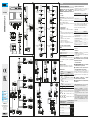
Descrizione e funzioni del dispositivo
Morsetti
~
~Alimentazione
B IN Ingresso linea X1 (X2)
B OUT Uscita linea bus X1
Connettore mini USB (CN1)
CN1 - Connettore per aggiornamento firmware del dispositivo.
☞ Il connettore non permette la programmazione
dell’impianto.
Trimmer di regolazione
P5 - Regolazione del livello audio verso il posto esterno.
P6 - Regolazione del livello audio verso i derivati interni.
LED di indicazione
Nome
Stato colore Significato
DL1 /
Rosso Trasmissione dati in corso su morsetto
(B OUT)
DL2 /
Rosso Trasmissione dati in corso su morsetto
(B IN)
DL3 /
Verde USB collegata
DL5 /
Giallo Reset memoria dati in corso
Legenda: acceso, lampeggiante
Configurazione dei jumper.
SW5 - Una volta rimosso permette l’aggiornamento firmware
del dispositivo, l’operazione deve essere svolta da personale
qualificato.
SW1 - SW2 - SW3 - Compensazione linea X1 totale
connessa sulla linea B IN.
SW7 - SW8 - SW9 - Compensazione linea X1 totale
connessa sulla linea B OUT.
Lunghezza totale del cavo
connesso ai morsetti
B IN: SW1 SW2 SW3
B OUT: SW7 SW8 SW9
<150 m (condizione di default)
>150 ÷ <350 m
>350 ÷ <650 m
>650 ÷ <1000 m
Configurazione dell’interruttore SW4.
Compensazione del tratto di linea X1 compreso tra
l’alimentatore XA/301LR (VA/08) o il posto esterno e il
derivato più distante o il successivo XAS/301.01.
Lunghezza totale del cavo SW4
<250 m (condizione di default)
>250 ÷ <500 m
Reset del dispositivo alle impostazioni di fabbrica.
Premere e mantenere premuto il tasto SW6; rilasciare il
pulsante solo quando il led DL5 smette di lampeggiare.
L’accensione per 2 secondi del led DL5, conferma che il
dispositivo è tornato alle impostazioni di fabbrica.
Dati tecnici
Tipo XAS/301.01
Alimentazione a 60Hz (V AC) 220-230
Corrente assorbita (
mA
AC
) 400
Tensione sul bus (V DC) 20
Corrente disponibile sul bus (A) 0,2*
Grado di protezione (IP) 30
Temperatura di funzionamento
(°C) 0 ÷ +35
Temperatura di stoccaggio (°C) -25 ÷ +70
* Per un 1 minuto su 3, la corrente disponibile sul bus può
essere 0,8 A.
Installazione
Il dispositivo deve essere installato, con o senza coprimorsetti,
in un armadio metallico resistente al fuoco.
La circolazione dell’aria attraverso le aperture del dispositivo
deve essere garantita.
L’alimentatore deve essere collegato ad una
linea di alimentazione protetta da un interruttore
magnetotermico da 20 A max.
Schemi di installazione
A Collegamenti possibili di XAS/301.01 in impianti
con selettore VSE/301 o con posti esterni.
B Collegamento di massimo due XAS/301.01 in
cascata in impianti citofonici o videocitofonici.
Con alimentazione da BUS, la distanza massima tra
alimentatore e ultimo derivato interno videocitofonico (con
cavo VCM/1D) è di 100 metri. Solo alimentando localmente
i derivati interni videocitofonici si possono raggiungere i 250
metri.
C Collegamento di XAS/301.01 in impianti
videocitofonici con più linee principali X1.
D Collegamento di XAS/301.01 in impianti citofonici/
videocitofonici.
Riferimenti normativi. Il prodotto è conforme alle direttive
applicabili, vigenti al momento della fabbricazione.
Dismissione e smaltimento. Non disperdere
nell’ambiente l’imballaggio e il dispositivo alla fine del ciclo
di vita, ma smaltirli seguendo le norme vigenti nel paese di
utilizzo del prodotto.
I componenti riciclabili riportano simbolo e sigla del
materiale.
I DATI E LE INFORMAZIONI INDICATE IN QUESTO MANUALE
SONO DA RITENERSI SUSCETTIBILI DI MODIFICA IN
QUALSIASI MOMENTO E SENZA OBBLIGO DI PREAVVISO.
LE MISURE, SE NON DIVERSAMENTE INDICATO, SONO IN
MILLIMETRI.
Istruzioni originali

FA01539M4A - 12/2021
РУССКИЙ
ИНСТРУКЦИИ ПО УСТАНОВКЕ
Внимание. Перед тем как приступить к монтажным
работам, внимательно прочитайте «ОБЩИЕ
ПРЕДУПРЕЖДЕНИЯ ПРИ МОНТАЖЕ», прилагаемые в
упаковке.
Описание
Устройство усиления аудио, видео и данных для основных
линий X2 и X1, с возможностью питания абонентских
устройств непосредственно от шины.
Позволяет расширить систему 300 X2 и X1 как с точки
зрения дистанций, так и с точки зрения количества
абонентских устройств.
Устройство имеет электронную защиту от перегрузок и
короткого замыкания.
Основные функции
- Подсоединение макс. 200 домофонов.
- Подсоединение макс. 100 видеодомофонов, из которых
только 1 активен.
- Подсоединение 2 усилителей XDV/300A в системы X1.
- Компенсация емкости линии на входе и выходе до 1 км.
- Автоматическая компенсация видео линии на входе
-26 дБ.
- Последовательное соединение с 2 XAS/301.01.
- Параллельное соединение с:
XAS 50/301.01 в системах 300
25 XAS/301.01 при подключении после вызывной
панели X2.
Описание и функции устройства
Клеммы
~
~Питание
B IN Вход линии X1 (X2)
B OUT Выход линии шины X1
Разъем мини USB (CN1)
CN1 - Разъем для обновления прошивки устройства.
☞ разъем не предназначен для программирования
системы.
Триммер-регулятор
P5 - Настройка уровня звука к вызывной панели.
P6 - Настройка уровня звука к абонентским устройствам.
Светодиод-индикатор
Название
Статус Цвет Значение
DL1 /
Красный Идет передача данных на клемму
(B OUT)
DL2 /
Красный Идет передача данных на клемму
(B IN)
DL3 /
Зеленый Подсоединено устройство USB
DL5 /
Желтый Идет сброс памяти
Описание: включен, мигающий
Конфигурация перемычки
SW5 - При удалении позволяет обновить прошивку
устройства, операция должна проводиться
квалифицированным персоналом.
SW1 - SW2 - SW3 - Полная компенсация линии X1,
подсоединенной к линии B IN.
SW7 - SW8 - SW9 - Полная компенсация линии X1,
подсоединенной к линии B OUT.
Общая длина кабеля,
подсоединенного к
клеммам
B IN: SW1 SW2 SW3
B OUT: SW7 SW8 SW9
<150 м (по умолчанию)
>150 ÷ <350 м
>350 ÷ <650 м
>650 ÷ <1000 м
Конфигурация переключателя SW4
Компенсация отрезка линии X1 между блоком питания
XA/301LR (VA/08) или вызывной панелью и более
отдаленным или последующим абонентским устройством
XAS/301.01.
Общая длина кабеля SW4
<250 м (по умолчанию)
>250 ÷ <500 м
Сброс устройства до восстановления заводских
настроек
Нажмите и удерживайте кнопку SW6; отпустите кнопку,
когда светодиод DL5 перестанет мигать.
Включение на 2 секунды светодиода DL5, подтверждает,
что устройство вернулось к заводским настройкам.
Технические данные
Тип XAS/301.01
Питание 60 Гц (В Пер. тока) 220-230
Потребление тока (
мА
перем.тока
)
400
Н
апряжение на шине (В пост. ток)
20
Ток на шине (A) 0,2*
Класс защиты 30
Рабочая температура (°C) 0 ÷ +35
Температура хранения (°C) -25 ÷ +70
* 1 минуту из 3, ток на шине может быть 0,8 A.
Установка
Устройство должно быть установлено, с или без защитной
крышки клемм, в металлическом корпусе, устойчивом к
возгоранию.
Должна быть гарантирована циркуляция воздуха через
отверстия устройства.
Источник питания должен быть подключен
к линии питания, защищенной термомагнитным
переключателем на 20 A макс.
Схемы установки
A Возможные подсоединения XAS/301.01 в
системы с переключателем VSE/301 или с
вызывными панелями.
B Подсоединение каскадом максимум
двух XAS/301.01 в системы домофонии и
видеодомофонии.
С питанием от шины, максимальное расстояние
между источником питания и последним абонентским
устройством (с кабелем VCM/1D) равно 100 метрам.
Дистанция в 250 метров может быть достигнута
только при локальном питании абонентских устройств
видеодомофона.
C Подсоединение XAS/301.01 в системы
видеодомофонии с несколькими основными
линиями X1.
D Подсоединение XAS/301.01 в системы
домофонии/видеодомофонии.
Нормативные ссылки. Продукция соответствует
применимым директивам, действующим на момент
изготовления.
Утилизация. Не выбрасывайте упаковку и устройство в
окружающую среду. Утилизируйте их в соответствии с
требованиями законодательства, действующего в стране
установки. На компоненты, подлежащие переработке,
нанесены знак и символ материала.
КОМПАНИЯ CAME S.P.A. СОХРАНЯЕТ ЗА СОБОЙ ПРАВО
НА ИЗМЕНЕНИЕ СОДЕРЖАЩЕЙСЯ В ЭТОЙ ИНСТРУКЦИИ
ИНФОРМАЦИИ В ЛЮБОЕ ВРЕМЯ И БЕЗ ПРЕДВАРИТЕЛЬНОГО
УВЕДОМЛЕНИЯ. ВСЕ РАЗМЕРЫ ПРИВЕДЕНЫ В ММ, ЕСЛИ НЕ
УКАЗАНО ИНОЕ.
ENGLISH
INSTALLATION INSTRUCTIONS
Attention. Before installing the unit, carefully read
the “WARNINGS FOR INSTALLATION” contained in the
package.
Description
Audio, video and data signal repeating device for the main
X2 and X1 lines, capable of supplying the internal receivers
directly from the bus.
It allows the 300, X2 and X1 system to be extended in terms
of distance and number of internal receivers.
The device is electronically protected against overloads and
short circuits.
Main functions
- Connection of max. 200 audio receivers.
- Connection of max. 100 video receivers of which only 1
is active.
- Connection of 2 XDV/300A amplifiers in X1 systems.
- Compensation of incoming and outgoing line capacity up
to 1 km.
- Automatic compensation of incoming video line up to -26
dB.
- Serial connection of up to 2 XAS/301.01.
- Parallel connection of up to:
50 XAS/301.01 in 300 system
25 XAS/301.01 if connected after an X2 entry panel.
Device description and functions
Terminal block
~
~Power supply
B IN X1 (X2) line input
B OUT X1 bus line output
Mini USB connector (CN1)
CN1 – Connector for device firmware update.
☞ The connector cannot be used for system programming.
Adjustment trimmer
P5 – Adjusts volume at entry panel.
P6 – Adjusts volume at internal receivers.
LEDs
Name
Status colour Key
DL1 /
Red Data transmission in progress on
terminal block (B OUT)
DL2 /
Red Data transmission in progress on
terminal block (B IN)
DL3 /
Green USB connected
DL5 /
Yellow Data memory reset in progress
Key: on, flashing
Jumper configuration
SW5 – Once removed, the device firmware can also be
updated. This must be done by qualified personnel.
SW1 - SW2 - SW3 - Compensation of total X1 line connected
on line B IN.
SW7 - SW8 - SW9 - Compensation of total X1 line connected
on line B OUT.
Total length of the cable
connected to terminals
B IN: SW1 SW2 SW3
B OUT: SW7 SW8 SW9
<150 m (default)
>150 - <350 m
>350 - <650 m
>650 - <1000 m
SW4 switch configuration
Compensation of the part of line X1 between the XA/301LR
(VA/08) supply unit or the entry panel and the receiver furthest
away or the next XAS/301.01.
Total cable length SW4
<250 m (default)
>250 - <500 m
Restore device to factory settings
Press and hold SW6; release only when LED DL5 stops
flashing.
The LED DL5 remains on for 2 seconds to confirm that the
device has been restored to factory settings.
Technical data
Type XAS/301.01
60Hz (VAC) power supply 220-230
Absorbed current (
mA
AC
) 400
Bus voltage (VDC) 20
Current available on the bus (A) 0.2*
Protection rating (IP) 30
Operating temperature (°C) 0 to +35
Storage temperature (°C) -25 to +70
* For 1 minute every 3, the available current on the bus
may be 0.8A.
Installation
The device must be installed, with or without terminal covers,
in a fire-resistant metal cabinet.
Air circulation through the device vents must be guaranteed.
The power supply unit must be connected to a
supply line protected by a circuit breaker, max. 20A.
Installation diagrams
A Possible XAS/301.01 connections in systems with
VSE/301 selector or with entry panels.
B Cascade connection of a maximum of two
XAS/301.01 in audio/video entry systems.
With a bus power supply, the maximum distance between the
power supply unit and the last internal video receiver (with
VCM/1D cable) is 100 metres. Only by powering from a local
supply can the internal video receivers reach 250 metres.
C Connection of XAS/301.01 in video entry systems
with several main X1 lines.
D Connection of XAS/301.01 in audio/video entry
systems.
Legal regulations. This product complies with the
applicable standards in force at the time of manufacturing.
Dismantling and disposal. Dispose of the packaging and
the device properly at the end of its life cycle, according to
the regulations in force in the country where the product
is used. The recyclable components bear the symbol and
code for the material.
The data and information provided in this manual are subject
to change at any time without prior notice. Measurements,
unless otherwise indicated, are in millimetres.
FRANÇAIS
INSTRUCTIONS POUR L’INSTALLATION
Attention. Avant de procéder à l’installation de
l’appareil, lire attentivement les “RECOMMANDATIONS
POUR L’INSTALLA
TION” contenues dans la boîte.
Description
Dispositif de répétition audio, vidéo et données pour lignes
principales X2 et X1, en mesure d'alimenter les postes
internes directement depuis le BUS.
Permet l'extension du système 300, X2 et X1 en termes de
distance et quantité de postes internes.
L'appareil est protégé électroniquement contre les surcharges
et les courts-circuits.
Fonctions principales
- Branchement de max. 200 interphones.
- Branchement de max. 100 portiers vidéo dont 1 seul actif.
- Branchement de 2 amplificateurs XDV/300A sur
installations X1.
- Compensation de la capacité de ligne en entrée et en sortie
jusqu'à 1 km.
- Compensation automatique de la ligne vidéo jusqu'à -26
dB en entrée.
- Branchement en série jusqu'à 2 XAS/301.01.
- Branchement en parallèle jusqu'à :
50 XAS/301.01 sur installations du système 300
25 XAS/301.01 si branchés après un poste extérieur X2.
Description et fonctions du dispositif
Bornes
~
~Alimentation
B IN Entrée ligne X1 (X2)
B OUT Sortie ligne bus X1
Connecteur mini USB (CN1)
CN1 - Connecteur pour mise à jour du micrologiciel du
dispositif.
☞ Le connecteur ne permet pas la programmation de
l'installation.
Trimmer de réglage
P5 - Réglage du niveau audio vers le poste extérieur.
P6 - Réglage du niveau audio vers les postes internes.
LED d'indication
Nom
État coleur Signification
DL1 /
Rouge Transmission de données en cours
sur borne (B OUT)
DL2 /
Rouge Transmission de données en cours
sur borne (B IN)
DL3 /
Vert USB connectée
DL5 /
Jaune Réinitialisation de la mémoire des
données en cours
Légende : accès, clignotant
Configuration des cavaliers
SW5 - Une fois supprimé, il permet la mise à jour du
micrologiciel du dispositif, l'opération doit être eectuée par
un personnel qualifié.
SW1 - SW2 - SW3 - Compensation de la ligne X1 totale
connectée à la ligne B IN.
SW7 - SW8 - SW9 - Compensation de la ligne X1 totale
connectée à la ligne B OUT.
Longueur totale du câble
connecté aux bornes
B IN: SW1 SW2 SW3
B OUT: SW7 SW8 SW9
<150 m (condition de défaut)
>150 ÷ <350 m
>350 ÷ <650 m
>650 ÷ <1000 m
Configuration de l'interrupteur SW4.
Compensation du morceau de ligne X1 compris entre
l'alimentateur XA/301LR (VA/08) ou le poste extérieur et le
poste le plus loin ou le suivant XAS/301.01
Longueur totale du câble SW4
<250 m (condition de défaut)
>250 ÷ <500 m
Réinitialisation du dispositif aux réglages faits en
usine
Appuyer et maintenir enfoncée la touche SW6 ; ne relâcher le
bouton que lorsque la led DL5 arrête de clignoter.
L’allumage pendant 2 secondes de la led DL5 confirme que le
dispositif est retourné aux réglages faits en usine.
Données techniques
Type XAS/301.01
Alimentation à 60Hz (VAC) 220-230
Courant absorbé (
mA
AC
)
400
Tension sur le bus (VDC) 20
Courant disponible sur le bus (A) 0,2*
Indice de protection (IP) 30
Température de fonctionnement (°C) 0 ÷ +35
Température de stockage (°C) -25 ÷ +70
* Pendant 1 minute sur 3, le courant disponible sur le bus
peut être 0,8 A.
Installation
Le dispositif doit être installé, avec ou sans cache-bornes,
dans une armoire métallique résistant au feu.
La circulation de l'air à travers les ouvertures du dispositif
doit être garantie.
L'alimentateur doit être branché sur une
ligne d'alimentation protégée par un interrupteur
magnétothermique de 20 A max.
Schémas d'installation
A Branchements possibles de XAS/301.01 sur
des installations avec sélecteur VSE/301 ou postes
extérieurs.
B Branchement de maximum deux XAS/301.01 en
cascade sur des installations d'interphone ou de
portier vidéo.
Avec alimentation depuis BUS, la distance maximale entre
alimentateur et dernier poste interne du portier vidéo (avec
câble VCM/1D) est de 100 mètres. Il n'est possible d'atteindre
250 mètres qu'en alimentant localement les postes internes
du portier vidéo.
C Branchement de XAS/301.01 sur des installations
de portier vidéo avec plusieurs lignes principales X1.
D Branchement de XAS/301.01 sur des installations
d'interphone/portier vidéo.
Références réglementaires. Le produit est conforme
aux directives applicables en vigueur au moment de la
fabrication.
Mise au rebut et élimination. Ne pas jeter l’emballage et
le dispositif dans la nature au terme du cycle de vie de ce
dernier, mais les éliminer selon les normes en vigueur dans
le pays où le produit est utilisé. Le symbole et le sigle du
matériau figurent sur les composants recyclables.
LES DONNÉES ET LES INFORMATIONS CONTENUES
DANS CE MANUEL SONT SUSCEPTIBLES DE SUBIR DES
MODIFICATIONS À TOUT MOMENT ET SANS AUCUN PRÉAVIS.
LES DIMENSIONS SONT EXPRIMÉES EN MILLIMÈTRES,
SAUF INDICATION CONTRAIRE.
Translation of the original instructions Traduction des instructions originales Перевод оригинальных инструкций
-
 1
1
-
 2
2


in altre lingue
- English: CAME 62704701 Installation guide
- français: CAME 62704701 Guide d'installation
Documenti correlati
-
CAME 62704701 Guida d'installazione
-
-
-
-
-
-
-
-
-