Abus TAS 112 Installation And Operating Instructions Manual
- Tipo
- Installation And Operating Instructions Manual

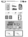
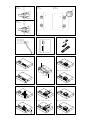
Abb./fig./schéma/afb./ill. 4.1 Abb./fig./schéma/afb./ill. 4.2
Abb./fig./schéma/afb./ill. 1
30,5
108
66
15,5
Abb./fig./schéma/afb./ill. 2
Abb./fig./schéma/afb./ill. 2a Abb./fig./schéma/afb./ill. 2b
KZS3/HZS3
KLZS/HLZS
TAS
SSB
2200
2300
TAS
4000/9000
4000/9000
Abb./fig./schéma/afb./ill. 3
7
1
4
5
2
6
3
8
D Montage- und Bedienungsanleitung
für ABUS Fenster-Scharnierseiten-Sicherung TAS 112

für
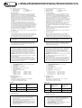
Schrauben
Ø
In Holz und Kunststoff
ohne Metalleinlage
Bohrer Ø
In Alu und Kunststoff
mit Metalleinlage
Bohrer Ø
3,5 mm
4,0 mm
4,0 mm
4,5 mm
4,8 mm
5,5 mm
Bohrtabelle
D Diese Anleitung ist wie folgt untergliedert:
I. Allgemeine Hinweise IV. Werkzeug
II. Einsatzmöglichkeit V. Montageanleitung
III. Packungsinhalt VI. Bedienung
I. Allgemeine Hinweise
Die Tür-Scharnierseiten-Sicherung TAS 112 ist nach den strengen
Prüfanforderungen der DIN 18104-1 und VdS 2536 anerkannt.
Durch DIN Certco ist TAS 112 zertifiziert „EINBRUCHHEMMEND
DIN-geprüft“. TAS 112 bietet zusätzlich Schutz gegen unberechtigtes
Eindringen in Räume. Gemäß DIN 18104-1 wird empfohlen,
dass pro 1 Meter Türhöhe rechts und links jeweils eine Zusatz-
sicherung montiert wird (wobei 1 Sicherung pro Tür mindestens
abschließbar sein soll). Polizei und Versicherer empfehlen dieses
ebenfalls.
Die optimale Schutzwirkung wird erreicht, wenn entsprechend
dieser Montage- und Bedienungsanleitung vorgegangen wird.
Die Befestigungsschrauben sollten zur Vermeidung von Überdrehung
mit einem geeigneten Werkzeug eingeschraubt und von Hand ange-
zogen werden. Ausschließlich ABUS-Befestigungsmaterial einsetzen.
Für eventuell auftretende Verletzungen bzw. Schäden, die bei der
Montage und/oder durch unsachgemäße Handhabung entstehen,
übernimmt der Hersteller keine Haftung!
Ein Zugang des gesamten Objektes muss von außen mittels Schlüssel
zu öffnen sein.
II. Einsatzmöglichkeit
TAS 112 wird auf der Scharnierseite der Tür montiert und eignet sich
für alle gängigen nach innen öffnenden Türen (Abb. 2). Die Montage
kann auf den Werkstoffen Holz, Kunststoff oder Alu erfolgen.
Die Türen können nach rechts oder links öffnen (Abb. 2a).
Achtung: Die Tür darf nicht weiter als 90° geöffnet werden.
Der Drehpunkt der Tür muss mindestens 8 mm von der Falzkante
entfernt liegen.
TAS 112 wird grundsätzlich auf der Innenseite montiert,
das Führungsblech auf dem Türblatt und das Gelenkmodul auf
dem Rahmen. Zusätzlich sollen auf der Griffseite der Tür geeignete
Zusatzsicherungen montiert werden.
Achtung: Befestigungshinweis:
Zum Erreichen einer besonders hoch belastbaren Verankerung
an Holz und Kunststoffrahmen den mitgelieferten Poweranker
verwenden. Bei Metallzargen empfiehlt sich die Verwendung von
ABUS Befestigungsanker BA oder das ABUS Befestigungsset IM 100.
Zu IM 100 wird ein geeigneter Verbundmörtel z.B. der Marke
Fischer FIS VS 150C, Hilti HFX oder ein ähnliches Produkt benötigt.
ABUS BA und ABUS IM 100 sowie Verbundmörtel sind im Handel
erhältlich.
Die in Abb. 2b zusätzlich gezeigten ABUS-Produkte sind ebenfalls
im Handel erhältlich.
(NL): Bei Kunststoffrahmen sollte eine Metalleinlage von min.
1,5 mm vorhanden sein. Falls nicht, ist der Einbau von 2 Stück BA
für dieses Produkt gemäß SKG-Anforderung in den Niederlanden
vorgeschrieben. ABUS BA und ABUS IM 100, sowie Verbundmörtel
sind ebenfalls im Handel erhältlich.
III. Packungsinhalt (Abb. 3)
1. 1 Gelenkmodul – Achtung: Gelenkmodul zusammenhalten
1 (mit Gummiring geliefert)
2. 1 Führungsblech
3. 1 Abdeckhaube für Führungsblech
4. 2 Poweranker
5. 2 Rahmendübel mit Schrauben 8 x 120 mm
6. 1 Rahmenabdeckung
7. 1 Unterlage (auch Bohrschablone)
8. Schrauben:
2 Stück M6 x 22 mm 2 Stück 4,8 x 15 mm
2 Stück M6 x 27 mm 4 Stück 4,8 x 32 mm
2 Stück M6 x 30 mm 2 Stück 4,8 x 50 mm
2 Stück M6 x 32 mm 4 Stück 5,5 x 50 mm
IV. Montagewerkzeug
Kreuzschlitzschraubendreher
Bohrmaschine
Feile, Säge zum Kürzen der Schrauben, ggf. Schraubstock
Steinbohrer 8 mm Ø (für 120 mm Tiefe)
Forstnerbohrer 20 mm Ø (für Poweranker)
V. Montageanleitung:
Wichtige Hinweise:
• Vor der Montage prüfen Sie bitte die Einstellung der Tür.
Stellen Sie sicher, dass sich die Tür die einwandfrei öffnen
und schließen lässt.
• Die Bohrlochtiefen bzw. die Schraubenlängen müssen auf die
örtlichen Gegebenheiten abgestimmt werden.
• Austreten des Bohrers bzw. der Schrauben auf der Rückseiten
vermeiden! Ggf. mit Bohranschlag arbeiten oder die vorhan-
denen Schrauben kürzen.
• Beim Bohren keine beweglichen Teile, Dichtungen oder Glas-
scheiben beschädigen.
for
screws
Ø
in wood or
synthetic materials
without metal liner
drill bit Ø
in aluminium and
synthetic materials
with metal liner
drill bit Ø
3.5 mm
4.0 mm
4.0 mm
4.5 mm
4.8 mm
5.5 mm
Drilling Table
G This instruction is divided into the following sections:
I. General Information IV. Tools
II. Application Options V. Installation Instruction
III. Package Contents VI. Operation
I. General Information
The hinge-side safety device for doors and windows TAS 112 is
certified according to DIN 18104-1 and VdS 2536. TAS 112 has
been certified as a “DIN tested BURGLAR RETARDANT” by DIN
Certco. TAS 112 offers additional protection against unauthorized
room access. According to DIN 18104-1, the installation of
2 additional safety devices, one each on the left and the right side,
is recommended per meter door height (with at least one safety
device per door needing to be lockable). The police and insurance
companies also recommend these measures.
Optimal protection is only achievable if the procedures described
in this installation and operating instruction are followed.
To avoid overtightening, fastening screws should be screwed in
with a suitable tool and tightened by hand. Only use ABUS mounting
materials.
The manufacturer does not assume any liability for any damages
and/or injuries sustained during installation and/or through
inappropriate handling.
The possibility to open one entrance of the overall object from the
outside with a key must exist.
II. Application Options
TAS 112 is installed at the door’s hinge side and is suitable for
all common doors opening towards the room interior (fig. 2).
Installation can be carried out on wood, synthetic materials or alu-
minium. The doors may open towards the left or the right (fig. 2a).
Please note: The door may not open any further than 90°.
The distance between the door’s pivot point and the rebate
edge needs to be at least 8 mm.
TAS 112 is principally mounted on the inside, the guidance plate
is mounted on the door leaf and the joint module on the frame.
Suitable supplementary safety devices should additionally be
installed on the door’s handle side.
Please note: Installation advice:
Please use the power anchor included to achieve a particularly
tough and load-resistant fastening on wood or synthetic frames.
For metal frames, using the ABUS fastening anchor BA or the
ABUS fastening set IM 100 is recommended. With IM 100,
a suitable composite mortar such as Fischer FIS VS 150C, Hilti HFX
or a similar product is required.
ABUS BA and ABUS IM 100 as well as the mortar are commercially
available.
The additional ABUS products shown in fig. 2b are also
commercially available.
(NL): A metal lining of at least 1.5 mm should be provided with
synthetic frames. If it is not already provided, the installation of
2 pieces BA is required for this product according to SKG specifi-
cations in the Netherlands. ABUS BA and ABUS IM 100 as well as
the composite mortar are also commercially available here.
III. Package Contents (fig. 3)
1. 1 Joint module – Note: hold joint module together
1 (with included rubber ring)
2. 1 Guidance plate
3. 1 Guidance plate cover
4. 2 Power anchors
5. 2 Frame plugs with screws 8 x 120 mm
6. 1 Frame cover
7. 1 Underlay (also drilling template)
8. Screws:
2 pieces M6 x 22 mm 2 pieces 4.8 x 15 mm
2 pieces M6 x 27 mm 4 pieces 4.8 x 32 mm
2 pieces M6 x 30 mm 2 pieces 4.8 x 50 mm
2 pieces M6 x 32 mm 4 pieces 5.5 x 50 mm
IV. Installation Tools
Crosshead screwdriver
Power drill
File and/or saw for shortening the screws, a vice, if required
Stone drill Ø 8 mm (for 120 mm depth)
Forstner bit Ø 20 mm (for power anchor)
V. Installation Instructions
Important advice:
• Please review the door adjustment before installation.
Ensure that the door can be opened and closed perfectly.
• Drill hole depths or screw lengths, respectively,
need to be adjusted to local conditions.
• Please avoid the drill or screws, respectively,
emerging at the back.
If required, work with a drill stop or shorten the screws used.
• Take care not to damage any movable parts,
seals or glass panes with the drill.
D Montage- und Bedienungsanleitung für ABUS Fenster-Scharnierseiten-Sicherung TAS 112
G Installation and Operating Instructions for ABUS hinge-side window safety device TAS 112

por
vis
de
Ø
dans du bois
ou du PVC sans
armature métallique
foret Ø
dans de l’aluminium
ou du PVC avec
armature métallique
foret Ø
3,5 mm
4,0 mm
4,0 mm
4,5 mm
4,8 mm
5,5 mm
Tableau de perçage
F Cette notice est structurée de la façon suivante:
I. Remarques générales IV. Outils nécessaires
II. Possibilité d’utilisation V. Notice de montage
III. Contenu de l’emballage VI. Utilisation
I. Remarques générales
Le dispositif de sécurité pour charnières (côté paumelles) TAS 112
répond aux exigences strictes des normes DIN 18104-1 et VdS 2536
(Allemagne). TAS 112 est certifié «retardateur d’effraction» par DIN
Certco. Le dispositif TAS 112 offre une protection supplémentaire
contre l’effraction. Selon la norme DIN 18104-1, il est conseillé
de monter un dispositif de sécurité supplémentaire tous les 1 mètre
de hauteur de la porte, à gauche et à droite (au moins 1 dispositif de
sécurité de la porte doit être verrouillable). Cela correspond égalment
aux recommandations de la police et des assureurs.
L’effet de protection optimum est atteint en suivant cette notice de
montage et d’utilisation. Afin d’éviter de forcer les vis en les serrant
trop, nous conseillons d’utiliser un outil approprié et de serrer les vis
à la main. Utilisez exclusivement le matériel de fixation ABUS.
ABUS décline toute responsabilité pour les dommages corporels ou
matériels qui pourraient éventuellement survenir lors de la pose et/ou
suite à un maniement incorrect! L’accès aux locaux doit être possible
de l’extérieur au moyen d’une clé.
II. Possibilité d’utilisation
Le dispositif de sécurité TAS 112 se monte sur le côté charnières de
la porte et est utilisable pour tous les modèles de portes courants
s’ouvrant vers l’intérieur (schéma 2). Il peut être monté sur du bois,
du PVC et de l’aluminium. Les portes peuvent s’ouvrir vers la droite
ou vers la gauche (schéma 2a).
Attention: Ne pas ouvrir la porte à un angle de plus de 90°.
Le centre de rotation de la porte doit se situer à au moins 8 mm
du bord de la feuillure.
Le montage de TAS 112 s’effectue toujours sur le côté intérieur de
la porte; la tôle de guidage est montée sur l’ouvrant et le module
d’articulation sur le dormant de la porte. En outre, des dispositifs
de sécurité supplémentaires appropriés sont à monter sur le côté
poignée de la porte.
Attention: Remarque concernant la fixation:
Sur des cadres en bois ou en PVC, utiliser l’ancre de fixation
ultra-résistant fourni avec le dispositif TAS 112 afin de réaliser un
ancrage particulièrement solide. Pour le montage sur des châssis
en métal, nous recommandons l’utilisation d’ancres de fixation
BA ABUS ou du set de fixation ABUS IM 100. IM 100 ne peut
être mis à l’œuvre qu’en liaison avec un mortier approprié,
tel que FIS VS 150C de Fischer, HFX de Hilti ou un produit similaire.
Les ancres de fixation ABUS et le set ABUS IM 100 ainsi que du
mortier sont disponibles dans le commerce spécialisé.
Les produits ABUS représentés dans la schéma 2b sont également
disponibles dans le commerce spécialisé.
(NL): Les cadres en PVC doivent être dotés d’une garniture
métallique d’au moins 1,5 mm d’épaisseur. Si cela n’est pas le cas,
l’utilisation de deux BA pour le montage de ce produit est obligatoire
dans les Pays-Bas, selon les exigences SKG. Les BA ABUS et le set
ABUS IM 100 ainsi que du mortier sont également disponibles dans
le commerce spécialisé.
III. Contenu de l’emballage (schéma 3)
1. 1 Module d’articulation – Attention: maintenir les pièces
1 du module ensembles (livré avec élastique)
2. 1 Tôle de guidage
3. 1 Couvercle pour la tôle de guidage
4. 2 Ancres de fixation ultra-résistants
5. 2 Chevilles avec vis de 8 x 120 mm
6. 1 Cache pour le cadre
7. 1 Support (faisant également office de gabarit de perçage)
8. Vis:
2 vis M6 x 22 mm 2 vis 4,8 x 15 mm
2 vis M6 x 27 mm 4 vis 4,8 x 32 mm
2 vis M6 x 30 mm 2 vis 4,8 x 50 mm
2 vis M6 x 32 mm 4 vis 5,5 x 50 mm
IV. Outils nécessaires
Tournevis cruciforme
Perceuse
Lime, scie pour raccourcir les vis, éventuellement étau
Foret à pierre Ø 8 mm (pour une profondeur de 120 mm)
Foret à pointe de centrage Ø 20 mm (pour l’ancre de fixation
ultra-résistant)
V. Notice de montage:
Remarques importantes:
• Veuillez vérifier l’ajustement de la porte avant le montage.
Assurez-vous que la porte ouvre et ferme correctement.
• La profondeur des alésages et la longueur des vis doivent
être adaptées aux circonstances locales.
• Éviter que le foret ou les vis transpercent le cadre! Utiliser
éventuellement une butée de perçage ou raccourcir les vis.
• Ne pas endommager de pièces mobiles, de joints ou de vitres
lors du perçage.
voor
schroeven
Ø
in hout en kunststof
zonder metalen inleg
boor Ø
in aluminium en kunststof
met metalen inleg
boor Ø
3,5 mm
4,0 mm
4,0 mm
4,5 mm
4,8 mm
5,5 mm
Boortabel
n Deze handleiding is als volgt onderverdeeld:
I. Algemeen IV. Gereedschap
II. Toepassingsmogelijkheden V. Montage-instructies
III. Inhoud van de verpakking VI. Bediening
I. Algemeen
Scharnierbeveiliger TAS 112 voor naar binnen draaiende elementen.
TAS 112 is volgens keuringseisen NEN 5096 SKG gecertificeerd.
De TAS 112 biedt daarnaast bescherming tegen onbevoegd binnen-
dringen van uw woning. Advies: monteer aan de scharnierzijde voor
maximale veiligheid 2 stuks per 1 meter hoogte. Op kunststof zonder
metalen kern dient u deze scharnierbeveiliger in combinatie met
ABUS BA bevestigingsanker te monteren. Optioneel verkrijgbaar,
zie voor montage in de handleiding van BA.
Optimale veiligheid wordt bereikt door nauwkeurig opvolgen
van deze montage- en gebruiksaanwijzing, Om overexpansie of
doldraaien van de bevestigingsschroeven te vermijden, draait u
handmatig en met passend gereedschap de schroeven vast.
Voor eventueel verwondingen en/of schade tijdens montage en/of
door ondeskundig gebruik ontstaan, aanvaardt de fabrikant geen
aansprakelijkheid.
II. Toepassingsmogelijkheid
TAS 112 wordt aan de scharnierkant van de deur gemonteerd en
is geschikt voor alle Gebruikelijke, langs binnen openende deuren
(afb. 2). De montage kan op de materialen hout, kunststof of alu-
minium gebeuren. De deuren kunnen naar rechts of links opengaan
(afb. 2a).
Opgelet: de deur mag niet verder dan 90° geopend worden.
Het draaipunt van de deur moet op een afstand van minstens
8 mm van de sponningkant gesitueerd zijn.
TAS 112 wordt in principe aan de binnenzijde gemonteerd,
de leiplaat op het deurblad en de scharniermodule op het kozijn.
Aanvullend dienen er aan de grijpzijde van de deur geschikte,
bijkomende beveiligingsinrichtingen gemonteerd te worden.
Opgelet: bevestigingsinstructie:
Om een uiterst hoog belastbare verankering aan kozijnen van hout
en kunststof te realiseren, maakt u gebruik van het bijgeleverde
Power-anker. Bij metalen kozijnen is de gebruikmaking van het
ABUS bevestigingsanker BA of van de ABUS bevestigingsset IM 100
aanbevelenswaardig. Voor IM 100 wordt een geschikte compositie-
specie, bijvoorbeeld van het merk Fischer FIS VS 150C, Hilti HFX,
of een gelijkaardig product benodigd.
ABUS BA en ABUS IM 100 evenals compositiespecie zijn in de
handel verkrijgbaar.
De in afb. 2b aanvullend getoonde ABUS-producten zijn eveneens
in de handel verkrijgbaar.
(NL): Bij kozijnen van kunststof dient er een metalen voering van
minstens 1,5 mm beschikbaar te zijn. Zo niet, is de inbouw van
2 stuks BA voor dit product in overeenstemming met de SKG-
vereiste in Nederland voorgeschreven. ABUS BA, ABUS IM 100 en
ook compositiespecie is eveneens in de handel verkrijgbaar.
III. Inhoud van de verpakking (afb. 3)
1. 1 scharniermodule – opgelet: scharniermodule klemmen
1 (met rubberen ring geleverd)
2. 1 Leiplaat
3. 1 Afdekkap voor geleideplaat
4. 2 Power-anker
5. 2 Kozijnpen met schroeven 8 x 120 mm
6. 1 Kozijnafdekking
7. 1 Support (ook boorsjabloon)
8. Schroeven:
2 stuks M6 x 22 mm 2 stuks 4,8 x 15 mm
2 stuks M6 x 27 mm 4 stuks 4,8 x 32 mm
2 stuks M6 x 30 mm 2 stuks 4,8 x 50 mm
2 stuks M6 x 32 mm 4 stuks 5,5 x 50 mm
IV. Montagegereedschap
Kruisgleufschroevendraaier
Boormachine
Vijl, zaag voor het inkorten van de schroeven, eventueel bankschroef
Steenboor 8 mm Ø (voor 120 mm diepte)
Forstner-boor 20 mm Ø (voor Power-anker)
V. Montage-instructies:
Belangrijke aanwijzingen:
• Gelieve vóór de montage de instelling van de deur na te kijken.
Zorg er beslist voor dat de deur foutloos geopend en gesloten
kan worden.
• De diepten van de geboorde gaten en ook de lengten van
de schroeven moeten op de plaatselijke omstandigheden
afgestemd worden.
• Het uitsteken van de boor en van de schroeven aan de achter-
zijden vermijden! Eventueel met booraanslag werken of de
beschikbare schroeven inkorten.
• Bij het boren geen beweegbare onderdelen, afdichtingen of
glazen ruiten beschadigen.
F Notice de montage et d’utilisation pour renfort-paumelles de fenêtre ABUS TAS 112
n Montage-instructies en gebruiksaanwijzing voor ABUS beveiligingsinrichting
voor vensterscharnierkant TAS 112

per
viti
Ø
in legno e plastica,
senza inserto di metallo
punta da trapano Ø
in alluminio e plastica,
con inserto di metallo
punta da trapano Ø
3,5 mm
4,0 mm
4,0 mm
4,5 mm
4,8 mm
5,5 mm
Tabella dei fori
I Queste istruzioni sono suddivise come segue:
I. Informazioni generali IV. Utensile
II. Possibilità d’impiego V. Istruzioni per il montaggio
III. Contenuto della confezione VI. Uso
I. Informazioni generali
La protezione TAS 112 sul lato delle cerniere della porta è
riconosciuta conformemente ai rigorosi requisiti di collaudo di
DIN 18104-1 e VdS 2536. Attraverso DIN Certco, TAS 112 ha
la certificazione «Collaudo DIN ANTIFURTO». TAS 112 offre in
aggiunta la protezione contro un accesso non autorizzato negli
spazi. Conformemente a DIN 18104-1 si raccomanda di montare
una protezione aggiuntiva rispettivamente per ogni metro di altezza
della porta, a destra ed a sinistra (per cui per ogni porta deve essere
possibile chiudere almeno una protezione). Questa procedura viene
raccomandata anche dalla polizia e dalle compagnie assicuratrici.
L’ottimale effetto di protezione viene ottenuto osservando e
attenendosi a queste istruzioni per il montaggio e l’uso. Le viti di
fissaggio devono essere avvitate con un utensile adeguato, e devono
essere serrate manualmente, al fine di evitare un serraggio eccessivo.
Deve essere usato esclusivamente materiale di fissaggio ABUS.
Il produttore non si assume nessuna responsabilità per eventuali
lesioni e/o danni insorti durante il montaggio e/o a causa di un
maneggio inappropriato.
L’accesso a tutto l’oggetto deve essere possibile, dall’esterno,
aprendo mediante una chiave.
II. Possibilità d’impiego
TAS 112 viene montato sul lato della cerniera della porta, e si adatta
a tutte le porte comunemente in uso che si aprono verso l’interno
(ill. 2). Il montaggio può essere effettuato sui materiali legno,
plastica, oppure alluminio. Le porte possono essere aperte verso
destra oppure verso sinistra (ill. 2a).
Attenzione: la porta non deve essere aperta più di 90°.
Il centro di rotazione della porta deve trovarsi almeno 8 mm
dal bordo del telaio.
TAS 112 viene montato in linea di principio sul lato interno, la lamiera
di guida deve essere montata sul battente e il modulo a cerniera deve
essere montato sul telaio. In aggiunta, sul lato della maniglia della
porta devono essere montate adeguate protezioni supplementari.
Attenzione: avvertenza per il fissaggio:
Per ottenere un ancoraggio in grado di sostenere un carico parti-
colarmente elevato su telai in legno e materiale plastico, è neces-
sario usare l’ancoraggio di rinforzo «Poweranker» compreso nella
fornitura. Per le intelaiature di metallo si raccomanda l'uso degli
ancoraggi di fissaggio ABUS BA, oppure del set di fissaggio
ABUS IM 100. Per IM 100 è necessaria un’adeguata malta com
posita, per es. della marca Fischer FIS VS 150C, Hilti HFX oppure
un prodotto equivalente. ABUS BA, ABUS IM 100 e la malta
composita sono comunemente reperibili in commercio.
Anche prodotti ABUS aggiuntivamente mostrati nella ill. 2b sono
comunemente reperibili in commercio.
(NL): Per i telai in materiale plastico deve esserci un inserto di
metallo di almeno 1,5 mm. In caso contrario, il montaggio di due
pezzi BA per questo prodotto, in Olanda, è previsto conforme-
mente ai requisiti SKG. Anche ABUS BA, ABUS IM 100 e la malta
composita sono comunemente reperibili in commercio.
III. Contenuto della confezione (ill. 3)
1. 1 Modulo a cerniera – Attenzione: tenere insieme il modulo
1 a cerniera (fornito con anello di gomma).
2. 1 Lamiera di guida
3. 1 Listello di copertura per la lamiera di guida
4. 2 Ancoraggi «Poweranker»
5. 2 Tasselli per telaio con viti 8 x 120 mm
6. 1 Copertura del telaio
7. 1 Elemento di spessoramento (anche maschera per foratura)
8. Viti:
2 pezzi M6 x 22 mm 2 pezzi 4,8 x 15 mm
2 pezzi M6 x 27 mm 4 pezzi 4,8 x 32 mm
2 pezzi M6 x 30 mm 2 pezzi 4,8 x 50 mm
2 pezzi M6 x 32 mm 4 pezzi 5,5 x 50 mm
IV. Utensile
Cacciavite con punta a croce
Trapano
Lima, sega per accorciare le viti, eventualmente morsa a vite
Punta da trapano per forare murature 8 mm Ø
(per 120 mm di profondità)
Trapano da legno 20 mm Ø (per ancoraggi «Poweranker»)
V. Istruzioni per il montaggio:
Informazioni generali:
• Prima del montaggio, controllare la registrazione della porta.
Accertarsi che la porta possa essere aperta e chiusa in modo
impeccabile.
• Le profondità dei fori trapanati e/o le lunghezze delle
viti devono essere armonizzate con le condizioni del luogo.
• Si deve evitare una fuoriuscita della punta del trapano
e/o delle viti sul lato posteriore!
Lavorare eventualmente con la battuta di trapanatura,
oppure accorciare le viti a disposizione.
• Trapanando si deve evitare di danneggiare le parti mobili,
le guarnizioni di tenuta, o le lastre in vetro.
I Istruzioni per il montaggio e l’uso per la protezione,
dal lato cerniera della finestra, TAS 112 ABUS

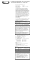
Abb./fig./schéma/afb./ill. 14.1
Abb./fig./schéma/afb./ill. 14. 2
Abb./fig./schéma/afb./ill. 13.1
Abb./fig./schéma/afb./ill. 13. 2
Abb./fig./schéma/afb./ill. 12.1
Abb./fig./schéma/afb./ill. 12. 2
Abb./fig./schéma/afb./ill. 11.1
Abb./fig./schéma/afb./ill. 11.2
Abb./fig./schéma/afb./ill. 10Abb./fig./schéma/afb./ill. 9.1
Abb./fig./schéma/afb./ill. 9.2
D
D
Abb./fig./schéma/afb./ill. 7 Abb./fig./schéma/afb./ill. 8 Abb./fig./schéma/afb./ill. 8a
D
C
C
F
Abb./fig.
schéma
afb./ill. 5.1
Abb./fig.
schéma
afb./ill. 5.2
BA
BA
Abb./fig.
schéma
afb./ill. 6.1
Abb./Fig.
Schéma
Afb./Ill. 6.2
E
E
D
C
C
E
E

390248 5/06
ABUS - Das gute Gefühl der Sicherheit
www.abus.com
D Technische Änderungen vorbehalten. Für Irrtümer und Druckfehler keine Haftung. ABUS © 2006
G Subject to technical alterations. No liability for mistakes and printing errors. ABUS © 2006
D Montage mit Poweranker:
Die mitgelieferte Unterlage ist gleichzeitig die Bohrschablone.
Durch Bohrung B mit Forstnerbohrer Ø 20,0 mm Kunststoffscheibe
durchbohren.
1. Bohrschablone auf Türblatt legen: bei Falzstärke unter 15 mm mit
der offenen Seite in den Raum zeigend (Abb. 4.1), bei Falzstärke ab
15 mm mit der geschlossenen Seite in den Raum zeigend (Abb. 4.2).
Pfeilspitzen lt. Abb. 4.1 und 4.2 mit der Mittellinie der Scharnier-
achsen in eine Flucht bringen. In dieser Stellung die Türblattkante
mit Bleistiftlinie oben und unten an der Bohrschablone anzeichnen.
2. Bohrschablone entlang der Türblattkante bis in die gewünschte
Montageposition vorschieben und anhand der Bleistiftmarkierungen
am Türblatt ausrichten (Abb. 5.1 und 5.2).
Bohrschablone in gewünschter Position mit 2 Schrauben durch die
2 Langlöcher (D) anschrauben und ausrichten. Durch Bohrung B
(mit Forstnerbohrer Ø 20,0 mm) 20 mm tief in den Rahmen bohren.
Löcher A und C Ø 3,5 mm vorbohren (Abb. 5.1 und 5.2).
3. Poweranker gemäß Abb. 6.1 und 6.2 einsetzen und ggf. ausrichten.
Achtung: Pfeile müssen generell senkrecht zueinander zeigen
(Abb. 6.1 und 6.2).
4. Durch die Schrägbohrung des Ankers schräg in das Mauerwerk
120 mm tief bohren und Rahmendübel mit Schraube einsetzen und
festschrauben (Abb. 7).
Löcher A aufbohren (Holz und Kunststoff ohne Metalleinlage:
Ø 4,0 mm; Metall und Kunststoff mit Metalleinlage: Ø 4,5 mm).
Gummiring von Gelenkmodul entfernen
(Achtung: Teile als Satz zusammenhalten).
Gelenkmodul aufsetzen, durch die Löcher A mit Schrauben
Ø 5,5 x 50 mm anschrauben (Abb. 8).
Durch die Löcher F mit Schraube M6 x 30 mm festschrauben.
Abdeckhaube aufsetzen, fest andrücken und einrasten lassen
(Abb. 9.1 und 9.2).
Weitere Montage ab 6.
Montage ohne Poweranker:
Die mitgelieferte Unterlage ist gleichzeitig die Bohrschablone.
1. Bohrschablone auf Türblatt legen: bei Falzstärke unter 15 mm mit
der offenen Seite in den Raum zeigend (Abb. 4.1), bei Falzstärke ab
15 mm mit der geschlossenen Seite in den Raum zeigend (Abb. 4.2).
Pfeilspitzen lt. Abb. 4.1 und 4.2 mit der Mittellinie der Scharnier-
achsen in eine Flucht bringen. In dieser Stellung die Türblattkante
mit Bleistiftlinie oben und unten an der Bohrschablone anzeichnen.
2. Bohrschablone entlang der Türblattkante bis in die gewünschte
Montageposition vorschieben und anhand der Bleistiftmarkierungen
am Türblatt ausrichten.
Profitipp: Zur besseren Fixierung der Bohrschablone 2 Stück
Schrauben 5,5 x 50 mm in Löcher E eindrehen bis die Schrauben-
spitzen leicht auf der Rückseite herausstehen. An richtiger Montage-
position diese Schraubenspitzen in den Türflügel drücken.
Die 6 Bohrungen A, B und C mit Ø 3,5 mm vorbohren (Abb. 5.1 und
5.2).
3. Die 4 Bohrungen A und B für das Gelenkmodul aufbohren
(Holz und Kunststoff ohne Metalleinlage: Ø 4 mm,
Metall und Kunststoff mit Metalleinlage: Ø 4,5 mm).
Sollte die Montage mit ABUS Befestigungsanker BA oder
ABUS IM 100 erfolgen (in NL ist ABUS BA durch SKG vorgeschrieben),
sind hierfür die Bohrungen B vorgesehen und es ist gemäß der
BA-Montageanleitung vorzugehen.
4. Gummiring von Gelenkmodul entfernen (Achtung: Teile als Satz
zusammenhalten). Mit 4 Schrauben 5,5 x 50 mm anschrauben
(Abb. 8). Abdeckhaube aufsetzen, fest andrücken und einrasten
lassen (Abb. 9.1 und 9.2).
Abb. 8a:
Montage Gelenkmodul (sollte dies einmal auseinanderfallen).
5. Vorderen Teil der Bohrschablone abbrechen oder abschneiden.
Hierdurch wird die Bohrschablone zur Unterlage (Abb. 10).
Abb. 10:
Bei Verwendung der Unterlage zur Schlossmontage
(Falzstärken von 0–15 mm), muss der vordere Teil der Unterlage
(nach dem Vorbohren) an den eingekerbten Stellen abgebrochen
bzw. abgeschnitten werden.
6. Bei Türen mit Falzstärke 0 –15 mm: Führungsblech mit Unterlage
verwenden. Hierzu Führungsblech auf die geschlossenen Seite der
Unterlage legen (rastet ein). Bei Türen mit Falzstärke 15– 30 mm:
Führungsblech ohne Unterlage verwenden.
Holztüren und Kunststofftüren ohne Metalleinlage: Führungsblech
mit 2 Schrauben 4,8 x 15 mm (ohne Unterlage) bzw. 4,8 x 32 mm
(mit Unterlage) durch die Langlöcher D nur leicht anschrauben
(Abb. 11.1 und 11.2), so dass sich das Führungsblech gerade noch
verschieben lässt.
Metalltüren und Kunststofftüren mit Metalleinlage:
Die beiden Bohrungen D auf 4 mm aufbohren und wie bei Holztüren
beschrieben weiterverfahren.
7. Führungsblech mit 2 selbstsichernden Schrauben M6 (Länge der
Schrauben lt. Tabelle aussuchen) mit dem Gelenkmodul leicht bis
zum Anschlag verschrauben und Schrauben eine Umdrehung
zurückdrehen (Abb. 12.1 und 12.2). Dann Führungsblech soweit
wie möglich in Richtung Tür (Griff) verschieben und Befestigungs-
schrauben (Langlochposition D) festdrehen.
Funktionskontrolle: Tür muss problemlos zu öffnen sein.
Wenn nötig, Führungsblech verschieben. Danach Führungsblech
endgültig mit längstmöglichen Schrauben 4,8 x 32 mm und oder
4,8 x 50 mm verschrauben.
8. Abdeckhaube bis zum Anschlag aufschieben (Abb. 13.1 und 13.2)
oder von oben aufklipsen (Abb. 14.1 und 14.2).
VI. Bedienung:
TAS 112 bewegt sich beim Öffnen/Schließen wie ein Gelenk und
muss nicht ver- oder entriegelt werden und ist somit bedienfrei.
Die beweglichen Teile sollen von Zeit zu Zeit geschmiert werden.
Soll die Tür ausgehängt werden, müssen unbedingt die beiden
Schrauben M6 (aus Abb. 12) entfernt werden.
G Installation with power anchor:
The underlay included also serves as the drilling template.
Drill through drill hole B with Forstner bit Ø 20.0 mm,
penetrating the plastic pane.
1. Place drill template on door leaf: if rebate width is less than 15 mm
with the open side facing the room (fig. 4.1), for rebate widths
starting from 15 mm with the closed side facing the room (fig. 4.2).
Align arrow points with the centre line of the hinge axes, as shown
in fig. 4.1 and 4.2. Mark the door leaf edge at the top and bottom
of the drill template in this position with a pencil.
2. Slide the drill template along the door leaf edge until it reaches the
desired position and align on the door leaf according to the pencil
markings (fig. 5.1 and 5.2).
Screw down and align drill template in desired position with 2 screws
through the 2 oblong holes (D). Drill to a depth of 20 mm through
drill marking B (with Forstner drill Ø 20.0 mm) into the frame.
Pilot-drill holes A and C Ø 3.5 (fig. 5.1 and 5.2).
3. Insert power anchor as shown in fig. 6.1 and 6.2 and align,
if required.
Please note: Arrows generally need to point towards each other
vertically (fig. 6.1 and 6.2).
4. Drill through the anchor’s slanted bore hole into the masonry at
an angle and to a depth of 120 mmm, insert frame plug with screw
and screw down (fig. 7).
Bore open holes A (wood and synthetic materials without metal liner:
Ø 4.0 mm, metal and synthetic materials with metal liner:
Ø 4.5 mm). Remove rubber ring from joint module
(Caution: keep parts together as a set).
Set down joint module and screw on through holes A using
Ø 5.5 x 50 mm screws (fig. 8). Screw down through holes F with
screw M6 x 30 mm. Apply cover, press on firmly and allow to lock
into place (fig. 9.1 and 9.2).
Follow further installation instructions from step 6 onwards.
Installation without power anchor:
The underlay included in the delivery also serves as the drilling
template.
1. Place drill template on door leaf: if rebate width is under 15 mm with
the open side facing the room (fig. 4.1), for rebate widths starting
from 15 mm with the closed side facing the room (fig. 4.2).
Align arrow points with the centre line of the hinge axes, as shown
in fig. 4.1 and 4.2. Mark the door leaf edge at the top and bottom
of the drill template in this position with a pencil.
2. Slide the drill template along the door leaf edge until it reaches the
desired position and align on the door leaf according to the pencil
markings.
Professional advice: For an optimal fixing of the drill template,
2 screws 5.5 x 50 mm screws into holes E until their points slightly
project through the back. Press these screw points into the door leaf
at the exact installation position.
Pilot-drill the six drill holes A, B and C with Ø 3.5 mm (fig. 5.1 and
5.2).
3. Bore open the 4 drill holes A and B for the joint module (wood and
synthetic materials without metal liner: Ø 4 mm, metal and synthetic
materials with metal liner: Ø 4.5 mm). If the installation is to be
carried out using ABUS fastening anchor BA or ABUS IM 100
(ABUS BA is prescribed by SKG in the Netherlands), use the drill
holes B dedicated to this purpose and proceed according to
BA installation instructions.
4. Remove rubber ring from joint module (caution: keep parts
together as a set). Screw down with 4 screws 5.5 x 50 mm (fig. 8).
Apply cover, press on firmly and allow to lock into place
(fig. 9.1 und 9.2).
Fig. 8a:
Joint module assembly (if it inadvertently comes apart).
5. Break or cut off front section of drill template.
This turns the drill template into an underlay (fig. 10).
Fig. 10: If the underlay is used for lock installation (rebate widths
from 0–15 mm), the front section of the underlay needs to be cut
or broken off at the points marked with notches (after pilot-drilling).
6. For doors with a rebate width of 0 –15 mm: use guidance plate in
combination with underlay. To do this, place guidance plate on the
closed side of the underlay (locks into place). For doors with a rebate
width of 15 – 30 mm: use guidance plate without underlay.
Wooden and synthetic doors without metal liner: screw guidance
plate down lightly using 2 screws 4.8 x 15 mm (without underlay) or,
respectively, 4.8 x 32 mm (with underlay) through oblong holes D
(fig. 11.1 and 11.2), so that guidance plate can just about still be
moved.
Metal doors and synthetic doors with metal liner:
bore open both drill holes D to a depth of 4 mm and proceed as
proscribed for wooden doors.
7. Lightly screw together guidance plate and joint module with
2 self-locking screws M6 (see drilling table for screw lengths) up to
the stop and then screw back screws one turn (fig. 12.1 and 12.2).
Now slide guidance plate in direction of the door (handle)
and tighten fastening screws (oblong hole position D).
Function control: door must be able to open easily.
Move guidance plate if necessary. Then finally screw down
guidance plate with the longest screws possible 4.8 x 32 mm
and or 4.8 x 50 mm.
8. Slide open cover until stop is reached (fig. 13.1 and 13.2)
or clip on from above (fig. 14.1 and 14.2).
VI. Operation:
TAS 112 moves like a joint when door is opened or closed, does
not require any bolting or unbolting and is hence operation-free.
Movable parts should be lubricated from time to time.
If the door is to be taken off its hinges, both screws M6 (see fig. 12)
unconditionally need to be removed.

390248 5/06
www.abus.com
F Nous nous réservons le droit de toutes modifications techniques. Nous n’assumons aucune responsabilité pour des erreurs ou défauts d’impression éventuels. ABUS © 2006
n Technische wijzigingen voorbehouden. Geen aansprakelijkheid voor vergissingen en drukfouten. ABUS © 2006
F Montage avec ancre de fixation ultra-résistant:
Le support sert en même temps de gabarit de perçage.
Percer à travers le disque de plastique par l’alésage B avec foret
à pointe de centrage Ø 20,0 mm.
1. Placer le gabarit de perçage sur l’ouvrant de la façon suivante:
Le côté ouvert vers l’intérieur dans le cas d’une feuillure de porte
d’une épaisseur inférieure à 15 mm (schéma 4.1), le côté fermé vers
l’intérieur dans le cas d'une feuillure de porte d'une épaisseur à partir
de 15 mm (schéma 4.2).
Aligner les pointes des flèches avec la ligne médiane des axes des
charnières (voir schéma 4.1 et 4.2). Dans cette position, marquer
au crayon l’arête de l’ouvrant sur la partie supérieure et la partie
inférieure du gabarit de perçage.
2. Déplacer le gabarit de perçage le long de l’arête de l’ouvrant jusqu’à
la position de montage désirée et l’ajuster à l’aide des marquages au
crayon effectués auparavant (schéma 5.1 et 5.2).
Visser le gabarit de perçage à la position désirée au moyen de deux
vis passées par les deux trous oblongs (D) et l’ajuster.
A travers l’alésage B, percer dans le cadre (avec foret à pointe
de centrage de Ø 20,0 mm) jusqu’à une profondeur de 20 mm.
Percer des avant-trous aux emplacements A et C avec un foret de
Ø 3,5 mm (schéma 5.1 et 5.2).
3. Insérer et éventuellement ajuster l’ancre de fixation ultra-résistant
selon schéma 6.1 et 6.2.
Attention: Les flèches doivent être perpendiculaires l’une à l’autre
(schéma 6.1 and 6.2).
4. A travers l’alésage biais de l’ancre, percer de biais dans le mur à une
profondeur de 120 mm ; insérer la cheville avec la vis et la serrer
(schéma 7).
Ouvrir les trous A à la perceuse (bois et PVC sans armature
métallique: Ø 4,0 mm; métal et PVC avec armature
métallique: Ø 4,5 mm). Oter l’élastique du module d’articulation
(Attention: Maintenir les pièces du module ensembles).
Poser le module d’articulation. Passer des vis Ø 5,5 x 50 mm
à travers les trous A et les serrer (schéma 8).
Fixer au moyen de vis M6 x 30 mm vissées à travers les trous F.
Poser le couvercle et bien appuyer jusqu’à ce qu'il s’encliquette
(schéma 9.1 et 9.2).
Suite de la description du montage à partir de point 6.
Montage sans ancre de fixation ultra-résistant:
Le support sert en même temps de gabarit de perçage.
1. Placer le gabarit de perçage sur l’ouvrant de la façon suivante:
Le côté ouvert vers l’intérieur dans le cas d’un recouvrement de porte
d’une épaisseur inférieure à 15 mm (schéma 4.1), le côté fermé vers
l’intérieur dans le cas d’un recouvrement de porte à partir de 15 mm
(schéma 4.2). Aligner les pointes des flèches avec la ligne médiane
des axes des charnières (voir schéma 4.1 et 4.2). Dans cette position,
marquer au crayon l’arête de l’ouvrant sur la partie supérieure et la
partie inférieure du gabarit de perçage.
2. Déplacer le gabarit de perçage le long de l’arête de l’ouvrant jusqu’à
la position de montage désirée et l’ajuster à l’aide des marquages au
crayon effectués auparavant (schéma 5.1 et 5.2).
Conseil de pro: Pour une meilleure fixation du gabarit de perçage,
tourner deux vis de 5,5 x 50 mm à travers les trous E jusqu’à ce que
les pointes des vis dépassent légèrement sur le dos. Placer le gabarit
de perçage à la bonne position de montage et presser les pointes des
vis contre l’ouvrant.
Percer 6 avant-trous aux emplacements A, B et C avec Ø 3,5 mm
(schéma 5.1 et 5.2).
3. Ouvrir à la perceuse les 4 alésages pour le module d’articulation aux
emplacements A et B (bois et PVC sans aramture métallique:
Ø 4,0 mm; métal et PVC avec armature métallique: Ø 4,5 mm).
Dans le cas d’un montage avec les ancres de fixation BA ABUS ou
le set ABUS IM 100 (l’emploi de BA ABUS est prescrit par SKG aux
Pays-Bas), utiliser les alésages B prévus à cet usage et procéder selon
la notice de montage du BA.
4. Oter l’élastique du module d’articulation (Attention: Maintenir les
pièces du module ensembles). Fixer au moyen de 4 vis 5,5 x 50 mm
(schéma 8). Poser le couvercle et bien appuyer jusqu'à ce qu'il
s'encliquette (schéma 9.1 et 9.2).
Schéma 8a: Montage du module d’articulation (si celui-ci devait
se disloquer).
5. Casser ou couper la partie avant du gabarit de perçage. De cette
façon, le gabarit de perçage devient un support (schéma 10).
Schéma 10: Dans le cas de l’utilisation du support pour le montage
d’une serrure (épaisseur de feuillure de porte de 0–15 mm),
la partie avant du support doit être cassée ou coupée aux endroits
entaillés (après le perçage des avant-trous).
6. Pour les portes ayant un recouvrement d'une épaisseur de 0 –15 mm:
Utiliser la tôle de guidage avec support. Pour ce faire, poser la tôle
de guidage sur le côté fermé du support (la tôle de guidage
s’encliquette). Pour les portes ayant un recouvrement d'une épaisseur
de 15 – 30 mm: Utiliser la tôle de guidage sans support.
Portes en bois et en PVC sans armature métallique:
Passer deux vis de 4,8 x 15 mm (sans support) ou de 4,8x 32 mm
(avec support) par les trous oblongs D et les serrer que légèrement
(schéma 11.1 et 11.2), de manière à ce que la tôle de guidage puisse
tout juste être encore déplacée.
Portes en métal et en PVC avec armature métallique:
A la perceuse, ouvrir les deux alésages D à un diamètre de 4 mm
et procéder comme pour les portes en bois.
7. Visser la tôle de guidage sur le module d’articulation jusqu'à la butée
au moyen de 2 vis indesserrables M6 (choisir la longueur des vis à
partir du tableau) puis donner un tour de vis dans le sens inverse
(schéma 12.1 et 12.2). Déplacer ensuite la tôle de guidage autant
que possible en direction de la porte (poignée) et serrer les vis de
fixation (position des trous oblongs D).
Contrôle de fonctionnement: La porte doit s’ouvrir sans problème.
Ajuster la tôle de guidage, si nécessaire. Ensuite, fixer définitivement
la tôle de guidage au moyen de vis de 4,8 x 32 mm ou 4,8x 50 mm
aussi longues que possible.
8. Poser le couvercle et le pousser jusqu’à la butée (schéma 13.1 et
13.2).ou le clipser par en haut (schéma 14.1 et 14.2).
VI. Utilisation:
Lors de l’ouverture et de la fermeture de la porte, TAS 112 fonctionne
comme une articulation et un vérouillage et un dévérouillage
– c’est-à-dire une manipulation – ne sont pas nécessaires.
Les pièces mobiles doivent être graissées de temps en temps.
Si la porte doit être décrochée, il faut absolument dévisser les deux
vis M6 (de schéma 12) auparavant.
n Montage met Power-anker:
Het bijgeleverde support is tegelijkertijd de boorsjabloon.
Door boring B met Forstner-boor Ø 20,0 mm kunststofruit
doorboren.
1. Boorsjabloon op deurblad leggen: bij een sponningdikte van minder
dan 15 mm met de open zijde in het lokaal wijzend (afb. 4.1),
bij een sponningdikte vanaf 15 mm met de gesloten zijde in het
lokaal wijzend (afb. 4.2).
Pijluiteinden volgens afb. 4.1 en 4.2 met de middellijn van de
scharnierassen in lijn brengen. In deze positie de deurbladkant
met potloodlijn bovenaan en onderaan aan de boorsjabloon
tekenen.
2. Boorsjabloon langs de deurbladkant vooruit tot in de gewenste
montagepositie schuiven en aan de hand van de markeringen
in potlood aan het deurblad uitlijnen (afb. 5.1 en 5.2).
Boorsjabloon in de gewenste positie met 2 schroeven door
de 2 slobgaten (D) vastschroeven en uitlijnen. Door boring B
(met Forstner-boor Ø 20,0 mm) 20 mm diep in het kozijn boren.
Gaten A en C Ø 3,5 mm vooraf boren (afb. 5.1 en 5.2).
3. Power-anker in overeenstemming met afbe. 6.1 en 6.2 aanbrengen
en uitlijnen.
Opgelet: pijlen moeten over het algemeen loodrecht tot elkaar wijzen
(afb. 6.1 en 6.2).
4. Door de schuine boring van het anker schuin in het metselwerk
120 mm diep boren en kozijnpen met schroef aanbrengen en
vastschroeven (afb. 7).
Gaten A uitboren (hout en kunststof zonder metalen voering:
Ø 4,0 mm; metaal en kunststof met metalen voering: Ø 4,5 mm).
Rubberen ring van scharniermodule verwijderen (opgelet: onder-
delen als set klemmen). Scharniermodule aanbrengen, door de
gaten A met schroeven Ø 5,5 x 50 mm vastschroeven (afb. 8).
Door de gaten F met schroef M6 x 30 mm vastschroeven.
Afdekkap aanbrengen, vast aandrukken en laten vast klikken
(afb. 9.1 en 9.2).
Verdere montage vanaf 6.
Montage zonder Power-anker:
Het bijgeleverde support is tegelijkertijd de boorsjabloon.
1. Boorsjabloon op deurblad leggen: bij een sponningdikte van minder
dan 15 mm met de open zijde in het lokaal wijzend (afb. 4.1),
bij een sponningdikte vanaf 15 mm met de gesloten zijde in het
lokaal wijzend (afb. 4.2).
Pijluiteinden volgens afb. 4.1 en 4.2 met de middellijn van de
scharnierassen in lijn brengen. In deze positie de deurbladkant met
potloodlijn bovenaan en onderaan aan de boorsjabloon tekenen.
2. Boorsjabloon langs de deurbladkant vooruit tot in de gewenste
montagepositie schuiven en aan de hand van de markeringen in
potlood aan het deurblad uitlijnen.
Professionele tip: voor een betere fixatie van de boorsjabloon
2 exemplaren van de schroeven 5,5 x 50 mm in de gaten E indraaien
tot de schroefuiteinden lichtjes aan de achterzijde uitsteken.
In de correcte montagepositie deze schroefuiteinden in de deur-
vleugel duwen.
De 6 boringen A, B en C vooraf met 3,5 mm boren (afb. 5.1 en 5.2).
3. De 4 boringen A en B voor de scharniermodule uitboren (hout en
kunststof zonder metalen voering: Ø 4 mm, metaal en kunststof
met metalen voering: Ø 4,5 mm). Indien de montage met het
ABUS bevestigingsanker BA of ABUS IM 100 doorgevoerd wordt
(in NL is ABUS BA door SKG voorgeschreven), zijn hiervoor de
boringen B voorzien en moet er in overeenstemming met de
BA-montage-instructies te werk gegaan worden.
4. Rubberen ring van scharniermodule verwijderen (opgelet: onder-
delen als set klemmen). Met 4 schroeven 5,5 x 50 mm vastschroeven
(afb. 8). Afdekkap aanbrengen, vast aandrukken en laten vast
klikken (afb. 9.1 en 9.2).
Afbeelding 8a:
montage scharniermodule (indien deze dan al eens uiteenvalt).
5. Voorste gedeelte van de boorsjabloon afbreken of afknippen.
Hierdoor wordt de boorsjabloon het support (afb. 10).
Afbeelding 10:
bij gebruikmaking van het support voor de slotmontage
(sponningdikten ven 0–15 mm) moet het voorste gedeelte van
het support (na het vooraf boren) op de ingekerfde plaatsen
respectievelijk afgebroken of afgeknipt worden.
6. Bij deuren met sponningdikte 0 –15 mm: geleideplaat met support
gebruiken. Hiervoor geleideplaat aan de gesloten zijde van
het support leggen (klikt vast). Bij deuren met sponningdikte
15 – 30 mm: geleideplaat zonder support gebruiken.
Deuren van hout en kunststof zonder metalen voering: geleideplaat
met 2 schroeven 4,8 x 15 mm (zonder support) c.q. 4,8 x 32 mm
(met support) door de slobgaten D slechts lichtjes vastschroeven
(afb. 11.1 en 11.2) zodat de geleideplaat nog net vooruit geschoven
kan worden.
Deuren van metaal en kunststof met metalen voering:
de beide boringen D op 4 mm uitboren en zoals bij houten
deuren beschreven verder te werk gaan.
7. Geleideplaat met 2 zelfborgende schroeven M6 (lengte van de
schroeven in overeenstemming met tabel uitzoeken) met de
scharniermodule lichtjes tot aan de aanslag vastschroeven en
schroeven één omwenteling achteruitdraaien (afb. 12.1 en 12.2).
Vervolgens geleideplaat zover mogelijk in de richting van de deur
(handgreep) verschuiven en bevestigingsschroeven (slobgatpositie D)
vastdraaien.
Controle van de werking: deur moet probleemloos geopend kunnen
worden. Zo nodig, geleideplaat verschuiven. Daarna geleideplaat
definitief met zo lang mogelijke schroeven 4,8 x 32 mm en/of
4,8 x 50 mm vastschroeven.
8. Afdekkap tot aan de aanslag erop schuiven (afb. 13.1 en 13.2)
of langs boven erop klikken (afb. 14.1 en 14.2).
VI. Bediening:
TAS 112 beweegt bij het openen/sluiten zoals een scharnier,
moet niet vergrendeld of ontgrendeld worden en is bijgevolg vrij
van bediening. De beweegbare onderdelen dienen van tijd tot tijd
gesmeerd te worden. Indien de deur uitgehangen moet worden,
moeten de beide schroeven M6 (uit afb. 12) onvoorwaardelijk
verwijderd worden.

I Montaggio con ancoraggio «Poweranker»:
L’elemento di spessoramento compreso nella fornitura è
contemporaneamente anche la maschera per foratura.
Mediante la perforazione B con trapano da legno Ø 20,0 mm
trapanare lo spessore in plastica.
1. Mettere la maschera per foratura sul battente: con uno spessore del
telaio inferiore a 15 mm con il lato aperto orientato nella stanza
(ill 4.1), con spessore del telaio da 15 mm con il lato chiuso orientato
nella stanza (ill. 4.2).
Portare in linea le punte delle frecce secondo le ill. 4.1 e 2.2 con la
linea mediana degli assi della cerniera. In questa posizione segnare
il bordo del battente con una riga di matita in alto e in basso sulla
maschera per foratura.
2. Fare avanzare la maschera per foratura lungo il bordo del battente
fino alla posizione di montaggio desiderata, e allineare al battente
servendosi delle marcature a matita (ill. 5.1 e 5.2).
Avvitare e allineare la maschera per foratura nella posizione
desiderata con 2 viti attraverso le due asole (D).
Mediante perforazione B (con trapano da legno Ø 20,0 mm)
trapanare 20 mm in profondità nel telaio. Eseguire fori di sgrosso
A e C Ø 3,5 mm (ill. 5.1 e 5.2).
3. Applicare ed eventualmente allineare l’ancoraggio «Poweranker»
conformemente alle ill. 6.1 e 6.2.
Attenzione: le frecce devono essere in linea generale orientate
verticalmente fra di loro (ill. 6.1 e 6.2).
4. Per la trapanatura obliqua dell’ancoraggio, eseguire la trapanatura
obliqua nella muratura a una profondità di 120 mm, applicare il
tassello per telaio con una vite e avvitare serrando bene (ill. 7).
Eseguire con il trapano i fori A (legno e plastica senza inserto
di metallo: Ø 4,0 mm; metallo e plastica con inserto di metallo:
Ø 4,5 mm). Rimuovere l'anello di gomma dal modulo a cerniera
(Attenzione: tenere insieme i pezzi come set).
Mettere il modulo a cerniera, avvitare attraverso i fori A con viti
Ø 5,5 x 50 mm (ill. 8). Attraverso i fori F avvitare e serrare con vite
M6 x 30 mm. Applicare il listello di copertura, premere bene e far
scattare in posizione (ill. 9.1 e 9.2).
Ulteriore montaggio da 6.
Montaggio senza ancoraggio «Poweranker»:
L’elemento di spessoramento compreso nella fornitura è
contemporaneamente anche la maschera per foratura.
1. Mettere la maschera per foratura sul battente: con uno spessore
del telaio inferiore a 15 mm con il lato aperto orientato nella stanza
(ill. 4.1), con spessore del telaio da 15 mm con il lato chiuso orientato
nella stanza (ill. 4.2).
Portare in linea le punte delle frecce secondo le ill. 4.1 e 4.2 con la
linea mediana degli assi della cerniera. In questa posizione segnare
il bordo del battente con una riga di matita in alto e in basso sulla
maschera per foratura.
2. Fare avanzare la maschera per foratura lungo il bordo del battente
fino alla posizione di montaggio desiderata, e allineare al battente
servendosi delle marcature a matita.
Consigli per professionisti: per fissare meglio la maschera per
foratura avvitare due viti 5,5 x 50 mm nei fori E, fino a quando
le punte delle viti sporgono leggermente sul lato posteriore.
Premere, sulla giusta posizione di montaggio, queste punte delle
viti nel battente della porta.
Eseguire i 6 fori di sgrosso A, B e C con 3,5 mm (ill. 5.1 e 5.2).
3. Eseguire i 4 fori da trapano A e B per il modulo a cerniera (legno e
plastica senza inserto di metallo: Ø 4,0 mm; metallo e plastica con
inserto di metallo: Ø 4,5 mm). Se il montaggio dovesse essere
eseguito con l’ancoraggio di fissaggio ABUS BA oppure ABUS IM 100
(in Olanda ABUS BA è prescritto da SKG), a tale scopo sono qui
previsti i fori da trapano B, e si deve procedere conformemente alle
istruzioni per il montaggio BA.
4. Rimuovere l'anello di gomma dal modulo a cerniera (attenzione:
tenere insieme i pezzi come set). Avvitare con 4 viti 5,5 x 50 mm
(ill. 8). Applicare il listello di copertura, premere bene, e far scattare
in posizione (ill. 9.1 e 9.2).
ill. 8a: montaggio modulo a cerniera (se dovesse staccarsi).
5. Separare o tagliare la parte anteriore della maschera per foratura.
Di conseguenza la maschera per foratura diventa lo spessoramento
(ill. 10).
ill. 10: usando lo spessoramento per il montaggio della serratura
(spessori del telaio di 0–15 mm), la parte anteriore dello
spessoramento (dopo avere eseguito i fori di sgrosso)
deve essere separata e/o tagliata sui punti incisi con una tacca.
6. Per porte con spessori del telaio 0 –15 mm: usare la lamiera di guida
con spessoramento. A tale riguardo, la lamiera di guida poggerà
sul lato chiuso dello spessoramento (scatta in posizione).
Per porte con spessori del telaio 15 – 30 mm: usare la lamiera di
guida senza spessoramento.
Porte di legno e porte di plastica senza inserto di metallo:
lamiera di guida con 2 viti 4,8 x 15 mm (senza spessoramento)
e/o 4,8 x 32 mm (con spessoramento), avvitare solo leggermente
attraverso le asole D (ill. 11.1 e 11.2), in modo tale che la lamiera
di guida si possa spostare ancora diritta.
Porte di metallo e porte di plastica con inserto di metallo:
eseguire con il trapano entrambi i fori D per 4 mm,
e procedere come descritto per le porte di legno.
7. Avvitare leggermente fino alla battuta la lamiera di guida con 2 viti
autobloccanti M6 (cercare la lunghezza delle viti secondo la tabella)
con il modulo a cerniera, e girare le viti di una rotazione in senso
antiorario (ill. 12.1 e 12.2). Spostare poi la lamiera di guida il più
possibile in direzione della porta (maniglia), e serrare bene le viti
di fissaggio (posizione dell’asola D).
Controllo di funzionamento: la porta si deve aprire senza problemi.
Se necessario, spostare la lamiera di guida. Avvitare poi definitiva-
mente la lamiera di guida con le viti più lunghe possibili 4,8 x 32 mm
e/o 4,8 x 50 mm.
8. Spingere il listello di copertura fino alla battuta (ill. 13.1 e 13.2),
oppure attaccare da sopra (ill. 14.1 e 14.2).
VI. Uso:
TAS 112 si muove aprendo/chiudendo come una cerniera,
e non deve essere bloccato o sbloccato, e non richiede pertanto
nessuna operazione. Ogni tanto le parti mobili devono essere
lubrificate. Se la porta dovesse essere tolta dal cardine,
allora si devono assolutamente rimuovere entrambe le viti M6
(da ill. 12).
390248 5/06
www.abus.com
I Ci si riservano modifiche tecniche. Per errori e refusi di stampa non ci si assume alcuna responsabilità. ABUS © 2006
-
 1
1
-
 2
2
-
 3
3
-
 4
4
-
 5
5
-
 6
6
-
 7
7
-
 8
8


Abus TAS 112 Installation And Operating Instructions Manual
- Tipo
- Installation And Operating Instructions Manual
in altre lingue
- English: Abus TAS 112
- français: Abus TAS 112
- Deutsch: Abus TAS 112
- Nederlands: Abus TAS 112
Documenti correlati
-
Abus FAS 101 Installation and Operation Instructions
-
-
-
-
-
-
-
-
-
