CARLO GAVAZZI UA18CAD04NKTI Manuale utente
- Tipo
- Manuale utente

Relief of cable strain Protection of the sensing face Switch mounted on mobile carrierTo avoid interference from inductive
voltage/ current peaks, separate the
prox. switch power cables from any other
power cables, e.g. motor, contactor or
solenoid cables
The cable should not be pulled
A proximity switch should not
serve as mechanical stop
Any repetitive flexing of the cable should be avoided
Ultrasonic M18 / M30
Ultraschall / Détecteur à ultrasons / Ultrasonidos /
Sensori ad ultrasuoni / Ultrasonisk
Diffuse, Digital and Analogue Output
Taster, analoge und digitale Ausgänge / Réflexion
directe-objet, sortie analogique / Detección directa, salida
analógica / Uscita analogica / Diffus, analog udgang
4 - 20 mA / 0 - 10 V / PNP / NPN
User Manual
Bedienungsanleitung / Manuel de l’utilisateur / Manual
del Usuario / Manuale d’istruzione / Brugerhåndbog
Schutz vor Überdehnung des
Kabels
Schutz der Sensorfläche des Schalters Mobiler NäherungsschalterUm Störungen durch induktive
Spannungs-/Stromspitzen zu vermeiden,
Kabel der Näherungsschalter getrennt von
anderen stromführenden Kabeln halten
Nicht am Kabel ziehen Näherungsschalter nicht als
mecha-nischen Anschlag verwenden
Wiederholtes Biegen des Kabels vermeiden
Tension des câbles
Protection de la face de détection du
détecteur
Détecteur monté sur support mobile
Pour éviter les interférences issues des pics
de tension et/ou des courants inductifs, veiller
à toujours faire cheminer séparément les
câbles d’alimentation des détecteurs de proxi-
mité et les câbles d’alimentation des moteurs,
contacts ou solénoïdes
Eviter toute contrainte en trac-
tion du câble
Ne jamais utiliser un détecteur de
proximité en tant que butée
mécanique
Eviter toute répétition de courbure dans le
cheminement du câble
Alivio de la tensión del cable Protección de la cara de detección Conector montado sobre portadora móvilPara evitar interferencias de tensión
inductiva/ picos de intensidad se deben
separar los cables del sensor del resto
de los cables de alimentación tales como
cables de motor, contactores o solenoides
No se debe tirar del cable
Un sensor de proximidad nunca
debe funcionar como tope mecánico
Evitar doblar el cable repetidas veces
Aflastning af kabel Beskyttelse af følerens tasteflade Aftaster monteret på bevægeligt underlagFor at undgå støjindflydelse fra induktive
strøm-/spændingsspidser skal aftaster-
kablet adskilles fra andre kraftkabler,
f.eks. fra motorer, transformatorer og
magnet-ventiler
Der bør ikke trækkes i kablet En aftaster bør ikke anvendes
som mekanisk stop
Gentagne bøjninger af kablet bør undgås
Posizione del cavo
Protezione della parte sensibile
del sensore
Sensore installato su pedana mobileAl fine di evitare interferenze di tipo elet-
trico, separare i cavi di alimentazione del
sensore di prossimità dai cavi di potenza
Il cavo non deve essere teso I sensori di prossimità non devono
essere usati per bloccaggi meccanici
Evitare qualsiasi flessione ripetuta del cavo
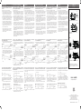
Detection Range
Erfassungsbereich / Distance de détection / Distancia de detección / Distanza di attivazione / Tasteafstand
3,97,9 11,8 15,7 19,7
-3,9
-3,1
-2,4
-1,6
-0,8
0,0
0,8
1,6
2,4
3,1
3,9
-100,0
-80,0
-60,0
-40,0
-20,0
0,0
20,0
40,0
60,0
80,0
0
0
100200 300400 500
Distance (Inches)
Parallel displacement (Inches)
Parallel displacement (mm)
Distance (mm)
100,0
Target Ø 25 mm
Target 100 x 100 mm
UA 18 CAD 04 ...
Ta
rget
Sensor
Y
X
0,07,9 15,7 23,6 31,5 39,4
Distance (Inches)
0200 400600 8001.000
Distance (mm)
-7,9
-5,9
-3,9
-2,0
0,0
2,0
3,9
5,9
7,9
Parallel displacement (Inches)
-200,0
-150,0
-100,0
-50,0
0,0
50,0
100,0
150,0
200,0
Parallel displacement (mm)
Target Ø 25 mm
Target 200 x 200 mm
UA 18 CAD 09 ...
Target
Sensor
Y
X
0,01,2 2,43,6 4,86,0 7,2
Distance (Feet)
-9,8
-7,9
-5,9
-3,9
-2,0
0,0
2,0
3,9
5,9
7,9
9,8
Parallel displacement (Inches)
0400 8001.200 1.6002.000 2.400
Distance (mm)
-250,0
-200,0
-150,0
-100,0
-50,0
50,0
100,0
150,0
200,0
250,0
Parallel displacement (mm)
0,0
Target Ø 25 mm
Target 200 x 200 mm
UA 18 CAD 22 ...
Ta
rget
Sensor
Y
X
Wiring Diagram
Schaltbild / Schéma de Câblage / Diagrama de Conexiones / Collegamenti Elettrici / Forbindelsesdiagram
Voltage
Spannung / Tension / Tensión /
Tensione / Spænding
Current
Strom / Courant / Intensidad /
Corrente / Effekt
Digital
Digital / Numérique / Digital /
Digitale / Digital
NPN:
PNP:
NK, PK
Voltage
NG, PG
Current
BN1
BK4
WH2
BU3
U
U
BN1
BK4
WH2
BU3
I
BN1
BK4
WH2
BU3
U
BN1
BK4
WH2
BU3
I
NP, PP
Digital
BN1
BK4
WH2
BU3
BN1
BK4
WH2
BU3
Rated operating distance (S
n
) Reference target: 1 mm
metal rolled finish.
CAD04: 100 x 100 mm
CAD09, 22 and 35:
200 x 200 mm
UA18CAD04... 50 - 400 mm
UA18CAD09... 100 - 900 mm
UA18CAD22... 200 - 2200 mm
UA30CAD35... 250 - 3500 mm
Blind zone
UA18CAD04... ≤ 50 mm
UA18CAD09... ≤ 100 mm
UA18CAD22... ≤ 200 mm
UA30CAD35... ≤ 250 mm
Beam angle
UA18CAD04... ±8˚
UA18CAD09... ±7˚
UA18CAD22... ±7˚
UA30CAD35... ±6˚
Sensitivity
Push-button P1 (longest setpoint)
P2 (shortest setpoint)
Rated operational voltage (U
B
) 12 (15) to 30 VDC
(ripple included)
No-load supply current (I
o
)
UA18CAD04... ≤ 45 mA @ U
B
max
UA18CAD09... ≤ 45 mA @ U
B
max
UA18CAD22... ≤ 50 mA @ U
B
max
UA30CAD35... ≤ 50 mA @ U
B
max
Output current continuous (I
e
)
Max. load capacity 100 nF ≤ 500 mA
UL508 specification ≤ 100
mA
UA30CAD35... ≤ 100 mA
Output analog output
NG.. or PG.. types 4 to 20 mA (Load ≤ 500 Ω)
NK.. or PK.. types 0 to 10 VDC (Load ≥ 3 kΩ)
Protection
Digital output Short-circuit, overvoltage
and reverse polarity
Supply Overvoltage and reverse
polarity
Analogue output Overvoltage
Environment
Installation category lll (IEC 60664/60664A;
60947-1)
Pollution degree 3 (IEC 60664/60664A;
60947-1)
Degree of protection IP67 (IEC 60529; 60947-1)
Ambient temperature
Operating (UA18)
-20° to +60°C (-4° to +140°F)
Operating (UA30)
-20° to +70°C (-4° to +158°F)
Storage (UA18 + UA30)
-35° to +70°C (-31° to +158°F)
Tightening torque
UA18 ≤ 1 Nm
UA30 ≤ 1.5 Nm
Technische Daten D
Nennreichweite (S
n
) Referenzziel: 1 mm
Walzmetalloberfläche.
CAD04: 100 x 100 mm
CAD09, 22 und 35:
200 x 200 mm
UA18CAD04 50 - 400 mm
UA18CAD09 100 - 900 mm
UA18CAD22 200 - 2200 mm
UA30CAD35... 250 - 3500 mm
Blindbereich
UA18CAD04... ≤ 50 mm
UA18CAD09... ≤ 100 mm
UA18CAD22... ≤ 200 mm
UA30CAD35... ≤ 250 mm
Öffnungswinkel der Schallkeule
UA18CAD04... ±8˚
UA18CAD09... ±7˚
UA18CAD22... ±7˚
UA30CAD35... ±6˚
Einstellungen der Schaltpunkte
Mit teach in Taste P1 (maximale Entfernung)
P2 (minimale Entfernung)
Nennbetriebsspannung (U
B
) 12 (15) bis 30 VDC
(inklusive Restwelligkeit)
Leerlaufstrom (I
o
)
UA18CAD04... ≤ 45 mA bei U
B
max
UA18CAD09... ≤ 45 mA bei U
B
max
UA18CAD22... ≤ 50 mA bei U
B
max
UA30CAD35... ≤ 50 mA @ U
B
max
Kontinuierlicher
Ausgangsstrom (I
e
)
Max. Lastkapazität 100 nF ≤ 500 mA
UL508-Spezifikation ≤ 100 mA
UA30CAD35... ≤ 100 mA
Analogausgang
NG..- und PG..-Typen 4 bis 20 mA (Last ≤ 500 Ω)
NK..- und PK..-Typen 0 bis 10 VDC (Last ≥ 3 kΩ)
Schutz
Transistorausgang Kurzschluss, Überspannung
und Verpolung
Versorgungsspannung Überspannung und
Verpolung
Analogausgang Überspannung
Umgebung
Überspannungkategorie lll (IEC 60664/60664A;
60947-1)
Verschmutzungsgrad 3 (IEC 60664/60664A;
60947-1)
Schutzart IP67 (IEC 60529; 60947-1)
Umgebungstemperatur
Betrieb (UA18) -20 bis +60 °C
Betrieb (UA30) -20 bis +70 °C
Lagerung -35 bis +70 °C
Anzugsdrehmoment
UA18 ≤ 1 Nm
UA30 ≤ 1,5 Nm
Caractéristiques F
Distance nominale de
fonctionnement (S
n
) Cible de référence : 1 mm
en métal laminé.
CAD04: 100 x 100 mm
CAD09, 22 et 35:
200 x 200 mm
UA18CAD04 50 - 400 mm
UA18CAD09 100 - 900 mm
UA18CAD22 200 - 2200 mm
UA30CAD35... 250 - 3500 mm
Zone aveugle
UA18CAD04... ≤ 50 mm
UA18CAD09... ≤ 100 mm
UA18CAD22... ≤ 200 mm
UA30CAD35... ≤ 250 mm
Angle de détection
UA18CAD04... ±8˚
UA18CAD09... ±7˚
UA18CAD22... ±7˚
UA30CAD35... ±6˚
Sensibilité
Bouton-poussoir P1 (consigne de la distance
la plus longue)
P2 (consigne de la distance
la plus courte)
Tension nominale de
fonctionnement (U
B
) 12 (15) à 30 Vcc
(ondulation incluse)
Courant d’alimentation à
vide (I
o
)
UA18CAD04... ≤ 45 mA à U
B
maxi
UA18CAD09... ≤ 45 mA à U
B
maxi
UA18CAD22... ≤ 50 mA à U
B
maxi
UA30CAD35... ≤ 50 mA à U
B
max
Courant de sortiec (I
e
)
Capacité de charge 100 nF ≤ 500 mA maxi
Norme UL508 ≤ 100 mA
UA30CAD35... ≤ 100 mA
Sortie analogique
Types NG.. ou PG.. 4 à 20 mA (Charge ≤ 500
Ω)
Types NK.. ou PK.. 0 à 10 Vcc (Charge ≥ 3 kΩ)
Protection
Sortie numérique Court-circuit, surtension et
polarité inverse
Alimentation Surtension et polarité
inverse
Sortie analogique Surtension
Environnement
Catégorie d’installation lll (IEC 60664/60664A;
60947-1)
Degré de pollution 3 (IEC 60664/60664A;
60947-1)
Indice de protection IP67 (IEC 60529; 60947-1)
Température ambiante
En fonctionnement (UA18) -20° à +60°C
En fonctionnement (UA30) -20° à +70°C
Stockage -35° à +70°C
Couple de serrage
UA18 ≤ 1 Nm
UA30 ≤ 1,5 Nm
Installation Hints / Installationshinweise / Conseils d’Installation /
Normas de Instalación / Consigli per l’Installazione / Installationsråd og -vink
Especificaciones E
Distancia nominal de
funcionamiento (S
n
) Objetivo de referencia:
Acabado metálico enrollado
de 1 mm.
CAD04: 100 x 100 mm
CAD09, 22 y 35:
200 x 200 mm
UA18CAD04 50 - 400 mm
UA18CAD09 100 - 900 mm
UA18CAD22 200 - 2200 mm
UA30CAD35... 250 - 3500 mm
Zona ciega
UA18CAD04... ≤ 50 mm
UA18CAD09... ≤ 100 mm
UA18CAD22... ≤ 200 mm
UA30CAD35... ≤ 250 mm
Ángulo de haz
UA18CAD04... ±8˚
UA18CAD09... ±7˚
UA18CAD22... ±7˚
UA30CAD35... ±6˚
Sensibilidad
Pulsador P1 (valor de consigna más
largo)
P2 (valor de consigna más
corto)
Tensión de funcionamiento de 12 (15) a 30 V CC
nominal (U
B
) (ondulación incluida)
Intensidad de alimentación
sin carga (I
o
)
UA18CAD04... ≤ 45 mA @ U
B
máx.
UA18CAD09... ≤ 45 mA @ U
B
máx.
UA18CAD22... ≤ 50 mA @ U
B
max.
UA30CAD35... ≤ 50 mA @ U
B
max
Intensidad de salida (I
e
)
Capacidad de carga máx. 100 nF ≤ 500 mA
Especificación UL508 ≤ 100 mA
UA30CAD35... ≤ 100 mA
Salida analógica de salida
Modelos NG.. o PG.. de 4 a 20 mA
(Carga ≤ 500 Ω)
Modelos NK.. o PK.. de 0 a 10 V CC
(Carga ≥ 3 kΩ)
Protección
Salida digital Cortocircuitos, sobreten-
sión y polaridad inversa
Alimentación Sobretensión y polaridad
inversa
Salida analógica Sobretensión
Entorno
Categoría de instalación lll (IEC 60664/60664A;
60947-1)
Nivel de contaminación 3 (IEC 60664/60664A;
60947-1)
Nivel de protección IP67 (IEC 60529; 60947-1)
Temperatura ambiente)
De funcionamiento (UA18) de -20° a +60°C
De funcionamiento (UA30) de -20° a +70°C
De almacenamiento de -35° a +70°C
Par de apriete
UA18 ≤ 1 Nm
UA30 ≤ 1,5 Nm
Specifiche I
Distanza di funzionamento
stimata (S
n
) Obiettivo di riferimento:
finitura di metallo laminato
da 1 mm.
CAD04: 100 x 100 mm
CAD09, 22 e 35:
200 x 200 mm
UA18CAD04 50 - 400 mm
UA18CAD09 100 - 900 mm
UA18CAD22 200 - 2200 mm
UA30CAD35... 250 - 3500 mm
Zona cieca
UA18CAD04... ≤ 50 mm
UA18CAD09... ≤ 100 mm
UA18CAD22... ≤ 200 mm
UA30CAD35... ≤ 250 mm
Angolo di apertura fascio
UA18CAD04... ±8˚
UA18CAD09... ±7˚
UA18CAD22... ±7˚
UA30CAD35... ±6˚
Sensibilità
Pulsante P1 (soglia più lunga)
P2 (soglia più corta)
Tensione di funzionamento
stimata (U
B
) da 12 (15) a 30 Vcc
(ondulazione residua inclusa)
Corrente di alimentazione
senza carico (l
o
)
UA18CAD04... ≤ 45 mA @ U
B
max
UA18CAD09... ≤ 45 mA @ U
B
max
UA18CAD22... ≤ 50 mA @ U
B
max
UA30CAD35... ≤ 50 mA @ U
B
max
Corrente di uscita (I
e
)
Massima capacità di carico
100 nF ≤ 500 mA
Specifica UL508 ≤ 100 mA
UA30CAD35... ≤ 100 mA
Uscita analogica di uscita
Tipi NG.. o PG.. da 4 a 20 mA
(Carico ≤ 500 Ω)
Tipi NK.. o PK.. da 0 a 10 Vcc
(Carico≥ 3 kΩ)
Protezione
Uscita digitale corto circuito, sovraten-
sione e inversione di polarità
Alimentazione Sovratensione e inversione
di polarità
Uscita analogica Sovratensione
Ambiente
Categoria d’installazione lll (IEC 60664/60664A;
60947-1)
Grado di inquinamento 3 (IEC 60664/60664A;
60947-1)
Grado di protezione IP67 (IEC 60529; 60947-1)
Temperatura ambiente
funzionamento (UA18) da -20° a +60°C
funzionamento (UA30) da -20° a +70°C
di stoccaggio da -35° a +70°C
Coppia torcente
UA18 ≤ 1 Nm
UA30 ≤ 1,5 Nm
Specifikationer DK
Nominel tasteafstand (S
n
) Referencemål: 1 mm
valset metaloverflade
CAD04: 100 x 100 mm
CAD09, 22 og 35:
200 x 200 mm
UA18CAD04 50 - 400 mm
UA18CAD09 100 - 900 mm
UA18CAD22 200 - 2200 mm
UA30CAD35... 250 - 3500 mm
Blind zone
UA18CAD04... ≤ 50 mm
UA18CAD09... ≤ 100 mm
UA18CAD22... ≤ 200 mm
UA30CAD35... ≤ 250 mm
Udstrålingsvinkel
UA18CAD04... ±8˚
UA18CAD09... ±7˚
UA18CAD22... ±7˚
UA30CAD35... ±6˚
Følsomhed
Trykknap P1 (længste indstillings -
punkt)
P2 (korteste indstillings -
punkt)
Nom. forsyningsspænding (U
B
) 12 (15) til 30 VDC
(inkl. ripple)
Ubelastet strømforbrug (I
o
)
UA18CAD04... ≤ 45 mA ved U
B
maks
UA18CAD09... ≤ 45 mA ved U
B
maks
UA18CAD22... ≤ 50 mA ved U
B
maks
UA30CAD35... ≤ 50 mA @ U
B
max
Kontinuerlig udgangseffekt (I
e
)
Max. load capacity 100 nF ≤ 500 mA
UL508 specification ≤ 100 mA
UA30CAD35... ≤ 100 mA
Analog udgang
NG.. eller PG.. typer 4 til 20 mA
(Belastning ≤ 500 Ω)
NK.. eller PK.. typer 0 til 10 VDC
(Belastning ≥ 3 kΩ)
Beskyttelse
Digital udgang Kortslutning, overspænding
og omvendt polaritet
Forsyning Overspænding og omvendt
polaritet
Analog udgang Overspænding
Ydre forhold
Installationskategori lll (IEC 60664/60664A;
60947-1)
Beskyttelsesgrad 3 (IEC 60664/60664A;
60947-1)
Tæthedsgrad IP67 (IEC 60529; 60947-1)
Omgivende temperatur
Drift (UA18) -20° til+60°C
Drift (UA30) -20° til+70°C
Lager -35° til +70°C
Tilspændingsmoment
UA18 ≤ 1 Nm
UA30 ≤ 1,5 Nm
Specifications GB
Parrallel Displacement / Paralleverschiebung / Déplacement
parallèle / Desplazamiento paralelo / Disallineamento paralle-
lo / Parallel displacement
Distance / Entfernung / Distance / Distancia / Distanza /
Distance
Inches / Zoll / Pouces / Pulgadas / Pollici / Tommer
Feet / Fuß / Pieds / Pies / Piedi / Fod
Distance (feet)
Distance (m)
0.5 1.0 1.5 3.0 3.50 2.0 2.5
1.6 3.3 4.9 9.8 11.50 6.6 8.2
Parallel displacement (mm)
0 0
100
200
300
400
-100
-200
-300
-400
3.9
7.9
11.8
15.7
-3.9
-7.9
-11.8
-15.7
Parallel displacement (inch)
UA 30 CAD 35 ...
Ta
rget
Sensor
Y
X

General set up of sensing point P1 (longest distance) and
Shortest distance (P2) independent on the sensor type
or function.
1) Mount the sensor in the selected application
2) Place a target in front of the sensor at the maximum
required distance (P1), then press shortly on the teach-
button, the Yellow LED switch Off and then On again
after maximum 2 seconds. The distance (P1) is now
saved in the sensor, and the target can be moved. I)
3) Place the target at the minimum distance requested (P2),
then press shortly on the teach-button, the yellow LED
turn Off then flash 5 times . The distance (P2) is now
saved in the sensor and the target can be moved. II)
I) P1 can be set to a maximum exceeding the family
specification for the sensor by removing the target in
front of the sensor, push and hold the teach-button more
than one second and the sensing distance is set at a
unique distance for this sensor only. Do not use this
function for an analogue output.
II) The second switch point can be set to minimum by
setting the target within the blind zone close to the
sensor head or by covering the sensor head with your
hand while teaching P2.
Sensors with 1 digital output and one analogue output
UA..CAD..PG/PK/NG or NK types
1) The factory setting is Normally Open N.O. for the digital
output and positive slope for the analogue output.
2) To reverse the slope to negative and reverse the N.O.
output to Normally Closed N.C. Push the teach-button
for 8 second (12 for UC18CAD22..) until the yellow LED
flash fast release the teach button and the LED will flash
5 times to acknowledge the change in function.
3) To switch back to positive slope or N.O. output, repeat
step 2.
Sensors with 2 digital outputs: UA..CAD..PP/NP types,
Normal sensing function or Adjustable Hysteresis
1) The factory settings is set at normal sensing function
2) Push the teach-button for 8 second (12 for UC18CAD22..)
until the yellow LED flash fast release the teach button
and the LED will flash 5 times to acknowledge the change
in function.
The sensor is now in Adjustable hysteresis mode.
3) To switch back to normal function, repeat step
Programming setup GB
Digital input
Digital input
distance
Configuración general del punto de detección P1 (distan-
cia más larga) y de la Distancia más corta (P2) independi-
entemente del tipo de sensor o la función.
1) Monte el sensor en la aplicación seleccionada
2) Coloque el objetivo delante del sensor a la distancia máx-
ima requerida (P1); a continuación, pulse brevemente el
botón “Teach”. El LED amarillo se apagará y después se
encenderá de nuevo tras un intervalo máximo de 2 segun-
dos. La distancia (P1) ahora estará guardada en el sensor,
y es posible mover el objetivo. I)
3) Coloque el objetivo a la distancia mínima requerida (P2);
a continuación, pulse brevemente el botón “Teach”. El
LED amarillo se apagará y después parpadeará 5 veces.
La distancia (P2) ahora estará guardada en el sensor, y es
posible mover el objetivo. II)
I) P1 puede ajustarse a un máximo que supere la espe-
cificación de la familia para el sensor retirando el objetivo
de delante del sensor; a continuación, pulse y mantenga
presionado el botón “Teach” durante más de un segundo
y la distancia de detección se ajustará a una distancia
exclusiva para este sensor únicamente. No utilice esta
función para una salida analógica.
II) El segundo punto de conmutación se puede ajustar
al mínimo colocando el objetivo dentro de la zona ciega
cerca del cabezal del sensor o cubriendo el cabezal del
sensor con la mano mientras se activa P2.
Sensores con 1 salida digital y una salida analógica, mod-
elos UA..CAD..PG/PK/NG o NK
1) El ajuste de fábrica es Normalmente abierto o N.A. para la
salida digital y pendiente positiva para salida analógica.
2) Para invertir la pendiente a negativa y para invertir la salida
N.A. a Normalmente cerrada N.C. Pulse el botón “Teach”
durante 8 segundos (12 en el caso del UC18CAD22..)
hasta que se ilumine el LED amarillo; suelte el botón
“Teach” y el LED se iluminará 5 veces, indicando el cam-
bio de función.
3) Para volver a la pendiente positiva o a la salida N.A., repita
el paso 2.
Sensores con 2 salidas digitales: Modelos UA..CAD..PP/
NP, función de detección normal o histéresis ajustable
1) La configuración de fábrica está ajustada a la función de
detección normal
2) Pulse el botón “Teach” durante 8 segundos (12 en el caso
del UC18CAD22..) hasta que se ilumine el LED amarillo;
suelte el botón “Teach” y el LED se iluminará 5 veces,
indicando el cambio de función.
El sensor ahora está en modo de histéresis ajustable.
3) Para volver a la función normal, repita el paso 2.
Configuración de la programación E
distancia
Función de vaciado BK 4, función de llenado WH 2
distancia
Digital input
distancia
Entrada digital
Pendenza negativa
Digital input
distance
distancia
Pendenza positiva
Entrada digital
Configuration générale du point de détection P1 (distance
maximale) et P2 (distance minimale), indépendante du
type ou de la fonction de capteur.
1) Installer le capteur dans l’application voulue
2) Positionner une cible devant le capteur à la distance max-
imale requise (P1) puis, appuyer brièvement sur le bouton
apprentissage : la LED jaune s’éteint puis s’allume à
nouveau au bout de 2 sec. maximum. La distance (P1) est
à présent enregistrée dans le capteur et on peut déplacer
la cible. I)
3) Positionner une cible devant le capteur à la distance min-
imale requise (P2) puis, appuyer brièvement sur le bouton
apprentissage : la LED jaune s’éteint puis clignote 5 fois.
La distance (P2) est à présent enregistrée dans le capteur
et on peut déplacer la cible. II)
I) On peut programmer le point P1 (distance maximale)
à une valeur unique, supérieure à celle spécifiée pour
cette gamme de produits : il suffit d’écarter la cible située
devant le capteur puis, de maintenir appuyé le bouton
d’ap prentissage plus d’une seconde. Ne pas utiliser cette
fonction avec un capteur à sortie analogique.
II) Pour programmer le point P2 (distance minimale ou
second point de commutation), il suffit de placer la cible
en zone aveugle près de la tête du capteur ou de masquer
la tête du capteur d’une main puis, d’appuyer sur le bou-
ton d’apprentissage.
Capteur à 1 sortie numérique et une sortie analogique
types UA..CAD..PG/PK/NG ou NK
1) Le réglage d’usine de la sortie numérique est NO ; la sortie
analogique est réglée d’usine avec une pente positive.
2) Inversion de la pente positive en pente négative et de la
sortie NO en sortie NF. Appuyer sur le bouton appren-
tissage pendant 8 secondes (12 s pour UC18CAD22..)
jusqu’à ce que la LED jaune clignote rapidement, et
relâcher le bouton-poussoir : la LED jaune clignote 5 fois
confirmant que la fonction a été modifiée.
3) Pour rétablir la pente positive ou la sortie NO, répéter
l’opération 2.
Capteurs avec 2 sorties numériques : types UA..CAD..PP/
NP, mode de détection normale ou hystérésis réglable
1) La sortie du capteur est réglée d’usine pour fonctionner en
détection normale.
2) Appuyer sur le bouton apprentissage pendant 8 secondes
(12 s pour UC18CAD22..) jusqu’à ce que la LED jaune
clignote rapidement, et relâcher le bouton-poussoir : la
LED jaune clignote 5 fois confirmant que la fonction a été
modifiée. A ce stade, le capteur est en mode hystérésis
réglable.
3) Pour rétablir le mode de détection normale, répéter
l’opération 2).
Configuration F
distance
Fonction Vidange BK 4, fonction remplissage WH 2
distance
Digital input
distance
Entrée numérique
Pente négative
Digital input
distance
distance
Pente positive
Entrée numérique
Generelle Einstellung der Schaltpunkte P1 (größte
Entfernung) und P2 (kürzeste Entfernung), unabhängig
vom Sensortyp und der Sensorfunktion.
1) Montieren Sie den Sensor
2) Platzieren Sie das Objekt ( Target ) an den am weitesteten
entfernten Schaltpunkt P1 und drücken Sie dann kurz die
Teach-in Taste. Die LED erlischt und leuchtet nach spä-
testens 2 Sekunden wieder. Nun ist der Schaltpunkt P1
gespeichert und das Objekt kann verschoben werden. I.)
3) Platzieren Sie das Objekt ( Target ) an den am kürzesten
entfernten Schaltpunkt P2 und drücken Sie dann kurz die
Teach-in Taste. Die LED erlischt und blinkt danach 5 mal.
Nun ist der Schaltpunkt P2 gespeichert und das Objekt
kann verschoben werden II.)
I) Schaltpunkt P1 kann auf die maximale Reichweite
eingestellt werden, indem die Teach-in Taste für mind-
estens eine Sekunde gedrückt wird, während sich
kein Objekt ( Target ) vor dem Sensor befindet. Dieser
Wert ist noch etwas größer als der Wert, welcher in
der Spezifikation der Nennreichweite angegeben wird.
Verwenden Sie diese Einstellung nicht bei den Sensoren
mit Analogausgang
II) Schaltpunkt P2 kann auf die minimale Reichweite
eingestellt werden, indem die Teach-in Taste für mind-
estens eine Sekunde gedrückt wird, während sich ein
Objekt (Target) im Blindbereich befindet oder beim
Einlernern von Schaltpunkt P2 die Sensorfront mit der
Hand abgedeckt wird.
Sensoren mit einem Digitalausgang und einem
Analogausgang UA..CAD..PG-/PK-/NG- oder NK-Typen
1) In der Werkseinstellung ist der Transistorausgang als
„Schließer (NO)” und der Analogausgang als „positive
Flanke” konfiguriert
2) Um von „positive Flanke“ auf „negative Flanke“ und
von „Schließer ( NO)“ auf „Öffner (NC)“ umzustellen
halten Sie die Teach-in Taste 8 Sekunden lang gedrückt
(UA18CAD22: 12 Sekunden ) bis die gelbe LED schnell
blinkt. Danach lassen Sie die Teach-in Taste los. Die LED
blinkt danach 5 mal um den Wechsel der Einstellung zu
bestätigen.
3) Um wieder auf „positive Flanke“ und „Schließer (NO)“
zurückzukehren wiederholen Sie Schritt 2)
Sensoren mit zwei Digitalausgängen: UA..CAD..PP/
NP-Typen, Betriebsarten „Normale Messfunktion“ oder
„Einstellbare Hysterese“.
1) Die Sensoren werden im Werk auf die Betriebsart
„Normale Messfunktion“ eingestellt
2) Um auf die Betriebsart „Einstellbare Hysterese“ umzus-
tellen halten Sie die Teach-in Taste 8 Sekunden lang
gedrückt ( UA18CAD22: 12 Sekunden ) bis die gelbe
LED schnell blinkt. Danach lassen Sie die Teach-in Taste
los. Die LED blinkt danach 5 mal um den Wechsel der
Betriebsart zu bestätigen.
3) Um wieder zur Betriebsart „Normale Messfunktion“
zurückzukehren wiederholen Sie Schritt 2)
Programmierung der Einstellungen D
Entfernung
Funktion Entleeren BK 4, Funktion Füllen WH 2
Entfernung
Digital input
Entfernung
Transistorausgang
Negative Flanke
Digital input
distance
Entfernung
Positive Flanke
Transistorausgang
Generel opsætning af aftastningspunkt P1 (længste
afstand) og P2 (korteste afstand) uafhængigt af sensor-
type eller funktion.
1) Sensoren monteres i den ønskede applikation.
2) Sæt et objekt foran sensoren på den foreskrevne maksi-
male afstand (P1) og tryk derefter kort på teach-knappen.
Den gule LED slukker og tænder igen efter højest 2
sekunder. Afstanden (P1) er nu gemt i sensoren og objek-
tet kan flyttes. I)
3) Placer objektet på den foreskrevne mindste afstand (P2)
og tryk derefter kort på teach-knappen. Den gule LED
slukker og blinker derefter 5 gange. Afstanden (P2) er nu
gemt i sensoren og objektet kan flyttes. II)
I) P1 kan indstilles til et maksimum der er højere end
specificeret for denne type sensor ved at fjerne objektet
foran sensoren. Man trykker og holder teach-knappen
mere end ét sekund og indstiller tasteafstanden på en
særlig afstand der kun gælder for denne sensor. Brug ikke
denne funktion til en analog udgang.
II) Det andet aftastningspunkt (P2) kan indstilles til mini-
mum hvis man placerer objektet inden for blinde zone tæt
på sensorhovedet eller ved at dække sensorhovedet med
hånden mens P2 indlæres.
Sensorer med en digital og en analog udgang UA..CAD..
PG/PK/NG- eller NK-typer
1) Fabriksindstillingen er normalt åben (N.O.) for den digitale
udgang og positiv hældning for den analoge udgang.
2) For at vende positiv hældning til negativ - og normalt åben
udgang (N.O.) til normalt lukket (N.C.), holdes teach-knap-
pen i 8 sekunder (12 for UC18CAD22..) indtil den gule
LED blinker hurtigt. Så slippes teach-knappen og LED’en
blinker 5 gange for at bekræfte funktionsændringen.
3) Hvis man vil skifte tilbage til positiv hældning eller N.O.-
udgang, gentages trin 2.
Sensorer med 2 digitale udgange: UA..CAD..PP/NP-typer,
normal aftastningsfunktion eller justerbar hysterese
1) Fabriksindstillingerne er sat til normal aftastningsfunktion.
2) Tryk teach-knappen ned i 8 sekunder (12 for UC18CAD22..)
indtil den gule LED blinker hurtigt. Så slippes teach-knap-
pen og LED’en blinker 5 gange for at bekræfte funk-
tionsændringen. Sensoren er nu i justerbar hysteresefunk-
tion.
3) For at skifte tilbage til normal funktion, gentag trin 2.
Konfiguration DK
Digital input
Digital input
distance
Impostazione generale del punto di rilevamento P1 (dis-
tanza più lunga) e della distanza più breve (P2) in base al
tipo o alla funzione del sensore.
1) Montare il sensore nell’applicazione selezionata
2) Collocare un obiettivo davanti al sensore alla distanza
massima richiesta (P1), poi premere brevemente sul pul-
sante teach, il LED giallo si spegne e si riaccende dopo
massimo 2 secondi. Adesso la distanza (P1) è stata mem-
orizzata e l’obiettivo può essere spostato. I)
3) Collocare l’obiettivo alla distanza minima richiesta (P1),
poi premere brevemente sul pulsante teach, il LED giallo
si spegne e poi lampeggia altre 5 volte. Adesso la distan-
za (P2) è stata memorizzata nel sensore e l’obiettivo può
essere spostato. II)
I) P1 può essere impostato al massimo, superando la
specifica di questa linea di sensori, rimuovendo l’obiet-
tivo davanti al sensore, spingere e mantenere premuto il
pulsante teach per più di un secondo e la distanza di rile-
va-mento è impostata ad una distanza specifica solo per
questo sensore. Non usare questa funzione per un’uscita
analogica.
II) Il secondo punto di commutazione può essere imposta-
to al minimo collocando l’obiettivo all’interno della zona
cieca vicino alla testina del sensore o coprendola con la
mano durante l’apprendimento P2.
Sensori con 1 uscita digitale e 1 uscita analogica, tipo UA..
CAD..PG/PK/NG o NK
1) L’impostazione di fabbrica è N.O. (normalmente aperta) per
l’uscita digitale e pendenza positiva per l’uscita analogica.
2) Per ripristinare la pendenza negativa ed invertire l’uscita
N.O. in uscita N.C. (normalmente chiusa). Premere il pul-
sante teach per 8 secondi (12 per UC18CAD22..) finché il
LED giallo lampeggia velocemente, rilasciare il pulsante
teach e il LED lampeggerà 5 volte a conferma del cambio
di funzione.
3) Per ritornare alla pendenza positiva oppure all’uscita N.O,
ripetere il passo 2.
Sensori con due 2 uscite digitali: tipi UA..CAD..PP/NP,
normale funzione di rilevamento o isteresi regolabile
1) L’impostazione di fabbrica è su normale funzione di rileva-
mento.
2) Premere il pulsante teach per 8 secondi (12 per
UC18CAD22..) finché il LED giallo lampeggia velocemente,
rilasciare il pulsante teach e il LED lampeggerà 5 volte a
conferma del cambio di funzione.
Adesso il sensore è in modalità Isteresi regolabile.
3) Per tornare alla funzione normale, ripetere il passo 2.
Impostazione della programmazione I
distanza
Funzione di svuotamento BK 4, Funzione di riempimento WH 2
distanza
Digital input
distanza
Ingresso digitale
Pendenza negativa
Digital input
distance
distanza
Pendenza positiva
Ingresso digitale
CARLO GAVAZZI
www.gavazziautomation.com
Certified in accordance with ISO 9001
Gerätehersteller mit dem ISO 9001/EN 29 001 Zertifikat
Une société qualifiée selon ISO 9001
Empresa que cumple con ISO 9001
Certificato in conformità con l’IS0 9001
Kvalificeret i overensstemmelse med ISO 9001
MAN UA18/UA30CAD MUL rev.02-10.2013
15-029-570
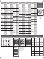
Dimensions
Abmessungen / Dimensions / Dimensiones / Dimensioni
/ Dimensioner
M18 cable / Kabel / câble / cable / cavo / kabel
M18 plug / Stecker / Connecteur / Conector /
Connettore / Stik
LED indication / LED-Anzeige / LED-d’indication /
Indicación LED / Indicatore a LED / LED-indikering
Teach / Teach-in / Apprentissage / Teach / Teach /
Teach
1÷2.5
63.5
17.6
12.4
3
8.3
3
M18 x 1
4.7O
83.6÷85.1
O25
22SW
Teach
LED indication
1÷2.5 57.5 17.6
77.7÷79.2
M12 x 1
14
8.3
3
22SW
O25
12.6
M18 x 1
Teach
LED indication
M30 cable / Kabel / câble / cable / cavo / kabel
M30 plug / Stecker / Connecteur / Conector /
Connettore / Stik
89.8
69.6
3
10
89.8
69.6
10
10
3
M 30 x 1.5 - 6g
M 12 x 1 - 6g
M 30 x 1.5 - 6g
O 4.7
Teach
Yellow Green
Teach
Yellow Green
Teach
Teach
89.8
69.6
3
10
89.8
69.6
10
10
3
M 30 x 1.5 - 6g
M 12 x 1 - 6g
M 30 x 1.5 - 6g
O 4.7
Teach
Yellow Green
Teach
Yellow Green
Teach
Teach
UA30
UA18
-
 1
1
-
 2
2


CARLO GAVAZZI UA18CAD04NKTI Manuale utente
- Tipo
- Manuale utente
in altre lingue
Documenti correlati
-
CARLO GAVAZZI UA30CAD60NPM1TI Manuale utente
-
CARLO GAVAZZI UA18EAD04NPTI Manuale utente
-
-
CARLO GAVAZZI UA18CSD03AGTI Manuale utente
-
-
CARLO GAVAZZI CA30CAF16PAM1 Manuale utente
-
CARLO GAVAZZI CA18CLL12BP Manuale utente
-
-
-
Altri documenti
-
Panasonic SCUA30 Manuale del proprietario
-
Asco Series 349 Electronic Pressure Switch Manuale del proprietario
-
-
-
-
-
-
Pepperl+Fuchs UMB800-18H40-I-2M Istruzioni per l'uso
-
SICK CM12 Capacitive proximity sensor Istruzioni per l'uso
-