
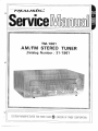
TM-1001
I\M1FM
STfrREO
TUNHR
Satnlog
[U
umber
: 31
-
I
961
CUSTÛM
I/ANUFACTUËIÐ
F0R
RADI0
SHACKEA
DMtStoN
0F
TANDy
CSRpSRAI¡¡N

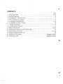
cÇNTENTS
Page
3&4
'w
ii{i,,t:
w
L
1.
2.
3,
4.
5,
6.
7,
8,
g.
10,
11.
i2.
I3.
\4.
D ISASSEMB
LY
I NSTRUCTIONS
DIAL
STRINGING
DIAGNAM
ALIGNMENTPROCEDURES
¡t...¡
7_
ALI.GNMËNT &
CHECK
POINTS
TROUBLESHOOTING .....i
.irr;.i..i,. 11*13
IC EQUIVALENT
CIRCUIT
..,.
13
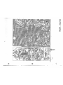
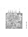
0063TUNEB
BOARD
$EMICONÞUCTOR
LËAD
IDËNTIFICATICIN
¡. ¡ ¡,I ¡ ¡
'
I
';
".
16
HI-ECTR,IüALPAnT$LIST
,
,r¡¡¡¡¡.i.¡¡.,,..16*22
MISCE
L LANEOUS PARTS
LIST
.......,23
$CHËMATIç ÞÌAGHAM,,,,.,.
;...,, r 1,
EXFLOÜID VIËW
..
,
,
SEPARATE
$HEET
5
6
6
I
@"'
i
k¿
v

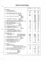
$PEC IF!CATIONS
\ùÉ'
wr
FM
$ECTION
1,
TUNING COVERAGE
2, IHF USABLE $ENSITIVITY'.
3.
IMAGE
REJECTION BATIO
(at
106 MHz)
4.
AFC
HOLDING
nANcE
(with
1 mV input)
WIDE
NABROW
5,
DIAL CALIBRAï|ON ACCURAOY
90 MHz
98
MHz
106 MHz
6.
lF BANDWIDTH
(6
dB down)
WIDE
NARROW
7. nISCRIMINATOR
BANDWTDTH
(p.eak-ro-peak)
8. OUTPUT VOLTAGE
{1
mV input)
MONO'50
Kohrn load
9. SIGNAL-TO-NOISË
RATIO
(1mV
input)
,lO
ULL LIMITING
(_3
dB}
11.
CAPTURE
RATIOgBMHz
(1
mV
input)
12. IHF
STLETTIVÍTY
WIDË
13.
OVF
NARBOW
V input)
14. rF
15"
n
l-{z)
WIDË
NARROW
kHz
kllz
1S.
Mr"JTti\¡Ê THnË$H0LF
17, Ålll
frFJfrtïl0N
{AM
30%,
FM
1007o Mod,}
at
9*
Mlrle,
1û0
-
20,000
¡iV
input
T8.
ü0 dB
üUIËTING SËNSITIVITY
at
98 fillf{:
Fi14
MFX
$gçTION
't.
$TËREû
SËP,EftATION
10ü H¿
WIIEINAHROW
{1
mV
input}
1
kHz WIDE/NAH
ROW
1ü
kH¿WlDE/NARRtw
P". STËffiçÐ
*ËÅt0fil $ENSÍTIVITY
iPitot
7
%)
3, ÐISTORTION
1l<Hz
(1
mV input)
WIDË
NAnnûw
4. Df-Ë*brFHÅ$l$
75
¡*$ec.
{at
5ü*15,0il0
H¡}
S.
ËSkl-*¿
LË4ffi4
,
{1
nr\l input}
S.
StA ftfrJËtïltfï
RATICI
{1
mV inpui}
7.
OUTPUT VOLTAGE
{i
mV
jnput}
*t ì kHz,5.* Kchm Load
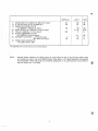
A1\{ SËtTffin}
1"
T{.i}*u{fSË
CüVËAÅüË
2.
$rN$lTlVITY
{for
20 dB
S
+
N/N
or 1û
% THD}
ñ,adiated, ãt
60û, 100û
anct 1400 kHz
Tern'¡i¡rat,"at
6Ð0, 1000 and 1400
kHz
3.
¡h4.å,GË
nËJË*TION
fiATt,0
{ar
1,40û
kHz}
4" OUTPt"lî
\1üLTAGE
{5
mV/m
input}
50
Kohm
Load
5.
ÐIAL CALIBHÃTION
ACCURACY
S00 kHz
I,ÛÛ0
6.
AGC FIGUHE
OF
MER''
T-,lbTI3
(from
100
mV/m
at 1,000
kHz)
{
NOMINAL
LIM IT UN IT
510*1060
87.5*108.5
1.7
8.8
78
r1
000
r800
400
850
vo'
1.2
1
45
76
0.2
90
0.1
0.2
I
45
38/30
40/35
32,28
7
0.?
0.4
Èl
-55
60
25û
25
40
320
760
45
52A162t
88*108
2.3
,13,5
70
1800
0.4
0,6
4
116
40
6
400
45
35
32013dB
r15
r30
t40
r500
r250
r350
r250
!1
50
ú100
300
85013dB
65
36
65
I
5
1.
2.
0.5
80
28120
32126
25/20
4*16
0,6
1.0
!2
*45
s0
760È3dB
38
kHz
MHz
¡"rv
dBf
dB
dB
dB
dB
¡.rv
%
()|
/o
dß
d8
dB
mV
¡rVlm
¡rV
CJB
mV
kHz
kHz
l<Hz
l<Hz
l<Hz
kHz
kHz
lcHz
mV
dB
¡,rv
dB
clB
dB
o/
/o
dB
o/
/o
Yo
¡.¿V
dB
¡¡V
l<Hz
l<Hz
kHz
dB
a

NOMINAL
32
30
50
0,8
4
10
LIM
IT
UNIT
7
,
SE LECTIV ITY
(at
1
,000
l<Hz,
200
¡rVlm
input)
8. lF REJEÇTION
RATIO
(at600
kHz)
9, SIGNAL.TO.NOI$E
RATIO
{at
1,000|<H2,,100
mV/m
input}
10, BAND WIDTH
(at
1,000
kHz,5 rnV/m input)
11.
THD
(at
1,000 kHz,5 mV/m input)
12,
AUDIO RËSPONSE
atZk9z
(at
1,000 l<H2,5
mV/m
input)
13.
AM BEAT
ht2t\l3l1l
1-50mV/m input
50*100
mV/m input
14, POWËR REOUIR.EMENTS
'
"AC
120V,60
Hz, 18W,
25
22
4A
ö-14
2
-6
10
15
dB
dB
dB
t<H¿
o/o
dB
%
o/
/a
"
AÇ
220124ôV,
50
llz
for
Eufopean
and
Auslralian Models.
NTTË:
W/
V/
Nornip*l
$pecs
represent
the design specs; all
units
should be able
to appr.ox[mate
these-some
will ex:eeed
and sorne may
drop slightly below these
specs.
Limit
Specs represent the absolute
worsl
rûndltisn which
$tilÌ might be
csnsidered
acceptable;
in no case should a unit
perform
to
le*s
thãn withìn any Lirnil
$pec,
4
@

ä
q
q
å,eTü.{* ¡i¡0.
i6{{çÊ }
úr¡r¡
¡0s€{
w1
9{t[ct9Ê
ì
M, fð.ÀüÕ,
f0{0!01
årÉ
4fiû,rÀ6tc
sv¡ [ÀfiÐ r{¡mt
î4,
itr:5r$
Sfr6
rr{xuÍ¡r{ð
$W]
úF¡ F¡!T:8
s{2
ES
OUT
tÉFT
CAAsilEt
rff
ouf
à¡GmcHAXil€L
M OUT
ep
r
o
r)
m
A
fl
g
Þ
Õ
Ð
Þ
K
{ûsd
('|
luq!ilË
&rô!4i
ilÉr{ã
!Ì1,'LIIPÅTH
ráEr:8
5ftâÉ0
rrÐ.
i¡€dl
rlzv
€r¡ ¡lüf¡
¡t33r
t\i
Íú
eÈE
$¡ir
f$ 0!(
tÊw
T¡¡IÂS
t¿¡ûI
^úicc
ffiÛl
¡9r¡!
Àü
0$¿
taûr
ÁS
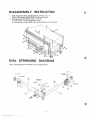
ANT,

DISAS$EMBLY
IN$TRT,ICTON
lr!et*:
Yuníng
eapacitor
should
be in fully
closed
position
1 . Removing chassis
f rom wooden
cabinet,
(
R
efer
to F í9. A)
Flemove five screws
(#38
&
#59)
from
sides
and
back.
2.
Removing the
Front
Panel,
(Befer
to
Fig,
A)
"
a)
Pulloff
the
Tuning and
Selector l<nobs.
b)
Remove four screws
(#26)
from
top and
bottom
of
Front Panel
DIAL
STRINGING
ÐIAGRAM
"Ð.6Ð
r: ,
w,
6
ry/

WF
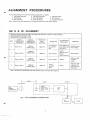
AL¡GNMENT
PROÇFDURES
Do
not âttempt
alignment
unless
the following
equipment is
available.
1. AM Signal Generator 4. FM
Signal
Generator
7.
Distortion
meter
2, Oscilloscope
5, Steleo MoclulaÌor
8. DC Voltmeter
3, AC Voltmeter
6.
Audio
Generator
g,
Frequency
Counter
l\ote: Remove lirre cord
antenrla from FM
exlernal antenna terminal
when
aligning.
AM IF & RF
ALIGNMENT
¡Ïct*:
Rsmpue Íine
cord ün¡eñfia Tr:om Ffu1
Ëxtërn¡l ãnïenna
terminal when
aligning.
ïUf\,Etl
Ë-*t:p
Å*t*t:na
ry
ÔUTPUT
fig-
I AfVl
ÀLIGNMË*IT
çS.I\]1\iECTION
Output-of signal
generator
shoulcl
be no
higher than necessary
to obtain an
output
reading.
Signal Generator Modlrlatïon :
30%,
Set SELECTOR
switch SW1 to ,AM.
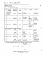
STEP
SIGNAL
GENËRATOR
COUPLING
SIONAL
GENERATOR
FREOUENCY
B ECEIVER
DIAL
SETTING
INDICATON
ADJUSTMENT
B'efer Fig.
4.
REMARKS
1
ftef*r
Fig.
1
600 kHz
{400
Hz
Mod.}
0.00
kHz
AC Voltmeter
To OUTPUT
jack
l*401
(OSC
Coil)
1451
(ANT
Coil)
T401
{tFT)
Adjust for fiaxi'
nlum
reading,
a
Sarne
as Step 1
1400
kHz
{4û0
Hz Mod,)
1400 kHz
Same
as
Step
1
TCl06
tuùu
rnmtnen
Tel 05
(ANT
Trirnmer)
Same
as
Step 1
3 S*me
as
*tsp
1
1üüû
kl'lz
{400
Hz Mod.)
1000 kHz Same
as
Step 1
VR402
Adjust
for
320
mV
Audio
output,
"4 $ar-'r* ar
Step
'l
'1üûü
kllz
{4üü
¡-l¿
Þ,{pd.}
1000
kþlz
TrJnerfs
TUIVING
Meter
VR4O1
Adjust for 707o
reading of
full
rcale with
input
oT þ m
v/m.
ÏUNEfi
FgONT
Ef!D
rc'to5,
Tcl06
L401
A'v¡ rË
T401
AC
Voltmster
SCOPE
ri
ãïTiñå Ì
t-rH
{F

FM
RF
AND IF ALIGNMENT
For
,ã.uro¡:*o*
r¡llc'deë,
Êhe icr¡¡sst
frequency
cf
f M
tuning range rhoultl not be
below
87.5
MHz,
12Sr?
tt12,5S¿)
Zr¿
=
Sttì
{?Sf¿}
50s¿
i75n)
Zout -
3004
{bala¡rcecl}
1 50fì
FM
Durrrmy
Antenna
to
300Q
antenna
terminal
of
Tuner:
"
Fis.2
FM
DUMMY
ANTENNA
B
Y.U/
db
Y¿//
Signal
generator
output
should
be no higher than necessary
to
obtain
an output reading,
Set Selector switch to
FM,
Signal Generator devìation;
75 kHz
NOTE:
Be sure to
disconnect
FM
line cord
antenna and
NARROW B/ïVlDTH
& AUTO.M TUNING
buttons should be
in the
"out"
position
during
alignment,
STEP
SIGNAL
GENERATCIB
COUPLING
SIGNAL
GENERATOB
FREOUENCY
TUNER
DIAL
SETTING
INDICATOR
ADJUSTMENÏ
Refer
Fig,4
REMARKS
1
Connect to FM
Antenna
Ter:mi-
nal
through
FM Dummy
Antenna
{300ç¿)
Fis,
2
No Signal
(on
or about
90 MHz)
DC
Voltmeter
connected to
Pin
33
& 34
L202
(Discriminator)
Adjust for
0V
reading on
DC Voltmeter
z Sarne
as
Step 1
90 MHz
(400
H¿, Mod,)
90 MHz
AC
Voltmeter
connected to
OUTFUT
jack
LI
04
(FM
OSC Coil)
L1 01
(FM
ANT
coìl)
'
L102, L103
(l'M
RF
Goíl)
Adiust
for
maximum
reading
on
AC Voltmeter
TC1
04
(FM
OSCTrim-
mer)
TCl
01
{FM
ANT Trírn-
mer)
TC102,
TC103
{FM
BF
Trim.
mer)
J
Sanre
as
S'rep
1
106
MH¿
{400
Hz, Mocl.}
106
MHz
Same
as
Step
2
\l
Adiust for
maxirnum
retding
steps ? & 3
improvcmenl
is
porsible.
$ani* *e
Step
f
9t
MHz
{40û
1-t:,
il.4od,}
90
L,4Hz
Same
as
Step
2
T2o1
(FM
rFT)
Adjust
for
maximunt
reading
q
Særæ er
$tep
1
CI8
ffiH¿
{4tû
È*4,
içlod.}
98 MHz
Distortion
Meter
connected
to
QUTPUT
jacl<
1zCI3
Adiust for
minimum
dístor.tion
fr
Sex'¡s
æs $*{s,
'l
û8lWHz
{4*0
l"*¿,
lMori.}
98 Mllz
Tunerls
TUNINÛ
Metor
VR2O1
Adjust for
7070
reading of'
full
scale with input
of
'l
rnV
?
$ac*e
as
8t*r¡
1
98,Ì?1il¡
{4ût
l*z &¡jod,}
98 ffillr
{Press
MUT*NG
Flt4
svvitchl
Oscilloscope
ccnnected to
OU"[PUT
iack
VB2O2
Adjust
so output
just
appears
with
an input
sÌgnal
Ievel
of
B
¡rV,
fu,

rus
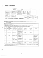
MPX ALIGNMENT
FM ANTENNA
l"EFIM INAL
(300f1)
TUNER
OUTPUT
TP
#41PIN
Fí9.3
RF,
lF
At\lÞ
MPX ALTGNMENT
CONNECTION
Note:
8e sure
to disconnecl FM
Line
Corcl
Antenna
ancl NARBoW
B/wlDTH
button
shoulcj
be
in
the
,,out,,position
during
alignmenl.
ry
FM SIGNAL
GENERATOR
FM
DUMN4Y
ANTE'!NA
300ç¿
FM
IF
T201
VR201
vn202
MPX
tc301
VR3O1
VR302
TUNER
FRONT
END
1103,1101
L102.
TC101
TC102,
TC103
L1 04
S:TEREO
MOÞULATOB
AUDIO
.GENFR.ATOR
F
requ
ency
Counter
AC,
Voltmeter
Tune lo
center 0f band,
Signal
ûcnerator
ouTpuf ievel;
1000¡.rV, Deviation:
toünÊct
Siçnal Generaror
tn
Ft\4
Antenna
Tsrminal
76!<Hz,
at 100
7o
modulat'ion
of composite
sígnal
through
FM Oummy
Antenna
(300O).
S*t SËLËTTOfr
Switch to FM.
P
I9 kl'lz
{P}LtT
SrûNÁ,1}
ù{ûDUL,ATIGT*
LeNel
OUTPUT
INDICATOR
Connected
to
ADJUST
Refer
Fig,
4
ADJUST
FOR
NOTË
t
Garrier
cllly
Frequency
Counter
Connect
to
TP
i#41
pin]
of PCB
û063
and
grounrl
VR3O1
10 kHz
¿
'T
kl-.rz
Ccrnpo:it*
*
eha*n*l
,qC
Voltrn€þr
to
ûUTFUT
iack
of
ft
channel
Adjust
input for
audio output
of
about 0,75
V
Cornpos̀
1 kþ{z L
rhan*el
,4C
Voitmet¿r
to
0LjTPUT
jack
ol R
channel
VB3T?
Minímum
AC
Vsltmeter
reading
shor-rlci
be
ät
leasr
32
dB below
reading
in
step
2.
4
tcrnposit*
1 kþlz
R
chsnnel
AC
VolTmeTsr"to
OUTPUT
jack
of L
channel
v4302
Minimunl
Same
as
Step
2,
tri
you
did
n*tobt¿in-t2d8-r*edings;n
rlaps 3
and 4
{compared
wíth
step Z}, rearljust
VR302
uniil
you
obtain
-32d8
rcading i*r h¡r*h
*teps 3 *nd 6.
I

T¡T1 L451
F 33
PIÑ
935
P¡N
VR3O1
ît:
fc¡û4
1103
L1s2
*4t
PtN
Ll$it
Þ
r
n
tt
z
Ë
rTI
z
4
F
f)
r
m
o
E
^
T
I
z,
-{
(.f,
*n
rlr
lå¡a
S¡
O
TÇlû6
¡'''
T€1û2
f,:'
Tclqs
i.-i,
TCIû1 1r:",
1401
Â,:
;:1.
VB4Tl
VR4O2
T401
.
VRz(]1
VR2O2
#34 PIN
L202
&
N
"cÞ
N
r@
$

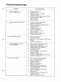
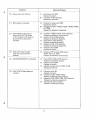
TROU
BLEShIOOTI
I\IG
"';
Symptom
Cause
and
Remedy
A)
Faulty
AC
power
cord
Replace
the
cord,
B)
Defect
in
the
power
switch
SW1
Replace
the
switch.
C) Broken
wire in the
power
transformer TB51
Replace
transformer
T851.
D)
Open
power
fuse
Replace
the fuse.
1)
Tuner
not
operative;
Pilot
lamp
does
not
light.
2l Fuse
blows when
power
is turned
on,
A)
B)
c)
n)
E)
Power
transformer
T851
defective
Replace
the
transformer.
Short
ín
tlie
primar.y
<rr
seconclary
of
the
transformer
circuitry
Repair
the
short.
Damaged
rectifier
D801
Replace
tlre
rectif
ier.
Short
in
the r,ectifier
circuit
Repair
the short.
Defective
C80?
& C803
(short)
Replace
the
capacitor(s).
3l
Pilot
lamp
does not light.
A)
Defective pitot
lamp{,s)
Replace
the lamp(s).
8)
Open
circuit in the
transformer
T851
ter.tiary
winding
R
eplace thê
tränsformçr.
4¡ Fllot
larr:p
lights
but no
ourpur
from
either
channel.
A) Resistor HBûl,
R804
damaged
(npen)
Replace
defective resistor{s).
B} tapacitor
t802,
C803
defective
(shorr)
Replace
the
defective
capacitor(s).
C) Dicde
ü8t1 damaEed
Heplace
the
cliode.
D) O¡:en
in
secondary
winding
of
power
transformer
T851
teplace
the transformer.
Ë)
TrsnsÌttor
TR801
& Tn803
damaged
{open),
Replace
the
trânsìstor{s).
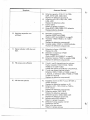
5) FM
does
not operate.
A}
ü)
c)
ü)
Foor
contact
in Selector
switch
SWZ
Repair
or
replace
the switch.
Besistor R307
defective
Replace
the
reÈistor.
Çapacitor C302
clefective
fiepface
the capanitor.
Defective
transisror
Tñ
1
û1-TR
1 03,
TR201"TR203,
TR301-TR401
or
tC
tc2t1-tc203,
tc301
FTeplace
the defective
component{s),
Defective
IFT
T201
Replaee
the
f
FT.
Defective
resistor
R104,
R209,
R214,
R228,
R321,
H323
Replace
the
defective
resístor(s),
Ë)
F)
i
A.$
v
'tr
11

Symptom
Cause and Remedy
G) Defectíve
capacitor
C104, C114,
C205,
c2CI7, C219,
C222,
C233,
C234
Replace
the
defective
capacitor(s),
Hl
Defective
coil L101-L104,
L201, L203
L204,
L301
Replace the
defective
coil(s).
l)
Faulty
lead-in
Repair:
or replace
the
lead-in.
J)
Diocle D207,
D208, D209,
D211
defective
Replace
defective
diode(s).
6) Multiplex
separation not
suff
icient
A) Deviation
in adjustment
Readjust VR301
and VH302.
(Refer
to
MPX
ALIGNMENT
on
page
g)
B) Transistol.TR30l-TR304
or lC 1C301
defective
Replace
the clefective
component(s).
C) Variable
resistor VR301
or
VR302
defective
Replace
the
defective
componenr(s).
7l Stereo
indicator LED does
not
tight.
A)
Defective
inclicator LED
0305
Replace
the
LED.
B) Deviation
in adjustment
VH301
Make readjustment.
{Beferto
MPX
ALIGNMENT
on
page
C)
Defective transistor
TR307
or resistor
Replace
the
defective
componentts),
e)
R306
ê¡
8l FM
volur¡e
not suf f ícient
A)
If
both L
and
.H
channels
have low volume:
Faulty
tran,sistor
TR
1 01
-TR
1 03, TR?01,
Tnzt2
or lt 1C201.1C203
Locate
and replace the
deTective
compCInent(sl.
B) If only
one
channol has low volume:
Þefsctive
lû301,
TR301
or
TR302 în case of
L
channel,
or
defective
1C301, TR303
or TH304
in case of R
channel
Hoplace
the
defective
cornponenT(s).
Sï ,&f*
c{s,e*
ft$?
Õp*râts.
A}
8)
C}
Þi
F}
F}
G)
îramirtor
and
lC
in
AM
lF
circrit
(TH401
or
1C401)
defec¡ive
Replace
the
defective
transistor or lC,
Þsfective
L401, T401,
CF401
or T402 in
tlre
lF
circuit
R eplace
the defective
component{ s).
Ðefective
resistor
H401,
H413
Replace the
defective
r.esistor(s).
Ðefeetive
capacitor
C403,
C405, Ç421
fi
eplace the defective
cafiacitor(s).
Selector
switch
SW2 defective
ßepair
or replace
the
switch,
ûefective Tuning
capacitor
VC101
H:eplace
the
VC101.
Open
în
the
bar
antenna
Repair
or replace
antenna,
b¿¿
tu¡
1
2

æ
,â
g
Symptom
Cause
and Remedy
10)
Stereo-rnono not
effectìve
A) Defective switch
SW2
Feplace
the switclr,
B) Transistor
TR307
defective
Replace the tran$istor,
1 1) Muting does not operate.
A) Defective
muting sw¡tch SW6
Êeplace the switch.
B) Damaged transistor TR203,
TR205, TR206, TR305
or TR306
Replace the defective
transistor($)
.
12Ì'
AUTO MAGIC
AFC
has
no
effect when AUTO"M
switeh
is ON
(lndicator
LËD
does not
go
out when tuning knob
is
touched);
A)
Transistor
TR204, TR701,
1C701
defective
Replace
the
defective component(s),
B)
Resistor R705, R706
defective
Replace the
clefective
resistor(s).
C)
Diocle
D701,.D7O2 defective
Replace the
defective diode(s).
D)
Capacitor Ç702, C704
defective
Replace
the
defectíve
capacitor(s).
E) Defective
switch
SW3
Beplace
the switch.
1Sï
Green
LËD
does not light
wlren th* tuning rontrol
is
relpased,
A)
Defective
R715
{open),
Ð304
(open)
TR701
(short)
or
1C701
Replace
the defective
component(s),
14l' ¡lAfifitW
SlWlDTll n*t e{fecrive
A) Diode D2Õ6, n206,
D210 defective
Feplace
the
defective diode(s),
BÌ Se,fsctive
sr¡¿itch
SW4
Ëeplace
the switch,
t) Def*ctive
ceramic filter
CF202,
CF203
Bepl*ce the filtar{s).
1$¡
i!{UT-TIP,4T|-{ l*etsr dr*s nsr
{u*c,ti**.
,A)
Ðefective
n¡eter M2
Replace
the meter.
8) Defectíve
1C204,
TR205-TR207
Re¡llace
the
defectlve component{
r),
t) Capacitor ç242,
C243, C,246, C247 defective
Fìenlace
the
defsctive eapacitor{s}.
D)
Diode D215, D216
defective
Replace
the defective diode{s}.
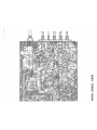
#
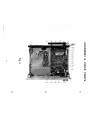
13

i'ìislr
tlt|lt¡Í
Àr{tTrfii}
fþf
i*¡rÍ
Ûrl"gttlF
AtJT0.¡ì
ö
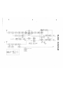
Õ
ffi
@
4
tr
\@
Æ
ffi'l
'Tl
ñ
w
fr
\d
Þ
æ

¡e{
w
4
ü
*w
s
m
Ë
Â_r
G}
¡
@i

t!
çi'
Þ:
j
Y
5ÉLECIoR
Ìrìü*i
8ltÌ1$
FrLl{n
rsr.¡1ff{û
ÂrlTf)"r¡r
4ÀftP{$
f.¡{fl!S
Ttt¡{lllü
¿t¡lJvliITi.r
{J{i.ÍMfi
(r¡
Õ
Õ
tr¡
(Á¡
-4
tn
t-
z
NT
tr
w
ö
T>
f-

iÕARÞ
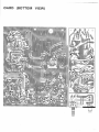
{ffitTTûruE
vãHW}
LEVEL
OUIPU
f
-
 1
1
-
 2
2
-
 3
3
-
 4
4
-
 5
5
-
 6
6
-
 7
7
-
 8
8
-
 9
9
-
 10
10
-
 11
11
-
 12
12
-
 13
13
-
 14
14
-
 15
15
-
 16
16
-
 17
17


in altre lingue
- English: Realistic TM-1001 User manual
- română: Realistic TM-1001 Manual de utilizare
Documenti correlati
Altri documenti
-
Chevrolet 985447 Radio Service And Shop Manual
-
Sony Security camera Manuale utente
-
Raymarine Ray 201 Manuale utente
-
Crown IC-150 Manuale utente
-
Sharp R-15AT Manuale utente
-
Pioneer SX-535 Manuale utente
-
Sharp R-23AM Manuale utente
-
Tektronix 7A18A Manuale utente
-
Technics SA-GX530 Manuale utente
-
Yamaha CR-820 Manuale del proprietario