
CHEVR.OLET
R.ADIO
SER,VICE
AND
SHOP
MANUAT
985432-PUSH
BUTTON
RADIO
985455-CHEVY
II PUSH
BUTTON RADIO
98543r
-MANUAT
RADTO
985453-CHEVY II I/IANUAL RADIO
985449-COR,VAIR
PUSH
BUTTON
RADIO
985447-CORVAIR
MANUAT RADIO
98539ó-CORVETTE
RADTO
985471-fnANUAt
TRUCK RADTO
985443-SERIES 95 MANUAT
TRUCK RADIO
98551 9-GUIDE.MATIC
HEADLAÍNP
CONTROL
FOR
I I6
3
FOR,EWOR.D
The
informqlion in lhis
service ond shop mqnuql
covers o
generol
description
of
Chevrolet Rqdios
qnd
Guide-Mqtic
Heodlomp
Control
for l9ó3
qnd
thorough
doto on operolions,
specificolions and
procedures
for lesling
ond
servicing
Chevrolet
Rodios
qnd
Guide-Mqtic
Heodlomp
Control.
CHEVROIET
MOTOR
DIVISION
GENERAT
MOTORS
CORPORATION
DETROIT 2, MICHIGAN
Copyr¡ght
I
9ó2
Chevrolet
Motor Division
Generol Molors Corporotion
ffi
Litho
in U,S,A¡
P&A
l9ó3
8.5M

INDEX
GENERAL
INFORMATION
-
ALL
MODELS
Electrical
DescriPtion
Procedure
for Checking
Inoperative
or
Noisy Radios
Procedure
for
Checking
and Servicing
Printed
Circuits
Procedure
for Checking
Transistors
Service
Procedure
for the
Push Button
and
Manual
Radios
Procedure
for Servicing
the Corvette
Radio
Procedure
for
Alignment
of AII Chevrolet
Radios
Capacity
and Inductance
Alignment
Procedure
for All Chevrolet
Radios.
985432
PUSH
BUTTON
RADIO
General
Information
Transistor
Complement
and Function.
.
Page
1
1
2
2
5
I
L2
13
Push Button
Setting
t4
t4
t4
14
16
18
t7
19
15
Condensed
MechanicaL
Operation
of
the
Push
Button
T\rner
Mechanical
Adjustment
of
Tuner
Procedure
for
Parts
Replacements
Radio
Circuit
Diagram
(Schematic
Drawing)
Service
Parts
List
Troubleshooting
the
Push Button
Radio
985431
MANUAL
RADIO
General
Information
Transistor
Complement
and
Function
.
. .
.
Circuit
Diagram
(Schematic
Drawing)
Service
Parts
List
Procedure
for
Part
Replacement.
. .
.
Troubleshooting
the
Manual
Radio
. . .
985449-985455
DELIIXE
PUSH
BUTTON
RADIOS
FOR CORVAIR
&
CHEVY
II
General Information
Transistor Complement
and
Function.
.
.
.
Push Button Setting
.
Condensed
Mechanical
Operation
of
the
Push
Button
T\rner
and
Radios
Tuner
Adjustments
for
985449
-
985455
Radios
Circuit
Diagram
(Schematic
Drawing)
Service
Parts
List
Procedure
for
Part RePlacement
Troubleshooting
the
Push
Button
Radio
98544?-985453
MANUAL
RADIOS
FOR CORVAIR
&
CHEVY
TI
General
Information
Transistor
Complement
and
Function.
Circuit
Diagram
(Schematic
Drawing).
Service
Parts
List
.
.
. .
.
Troubleshooting
the
Manual
Radio
. . . .
2t
2l
22
2l
2L
22
2t
27
27
28
31
29
33
31
28
38
38
40
38
38
46
General Information
985396 CORVETTE
RADIO

985396
CORVETTE
RADIO
(Cont'a.
)
Tube
and Transistor
Complement and Function
Push
Button
Setting
Operation of
the
Wonder Bar Tuner
Mechanical
Adjustment
Procedure
for
Part
Replacement. . .
Circuit Diagram
(Schematic
Drawing).
Service Parts
List
Troubleshooting
the
Wonder Bar
Radio.
985471
TRUCK
RADIO
General
Information
Transistor
Complement and Function.
.
Circuit
Diagram
(Schematic
Drawing).
. . .
Service
Parts
List
Troubleshooting
the Manual
Radio
985443
SERIES
95 TRUCK
RADIO
General
Information. .
Transistor
Complement
and Function.
.
Circuit
Diagram
(Schematic
Drawing).
Service Parts
List
Troubleshooting
the Manual
Radio
985519
GUIDE-MATIC
HEADLAMP
CONTROL
Adjustments
and Tests
General
Description
Circuit Diagram
(Schematic
Drawing)
Functional
Operation
Sensitivity
Tests
Service
Parts
List
.
Trouble
Shooting
Procedure
Vertical
Aim. .
Page
46
46
47
47
51
52
55
55
66
66
68
67
66
60
59
63
60
59
74
73
78
74
76
79
74
?6

CHEVROLET
RADIO
SERVICE
AND SHOP
MANUAL
Electrical
DescriPtion
The
circuit
used
in
the
Chevrolet
receivers
are
of
the
superheterodyne
type
that
use
no regenera-
tion.
The tuning
circuits
are
of
the
permeability
type and
are
tuned
by varying
iron
cores in and
out
of
the antenna,
radio
frequency, andoscillator
coils
like
pistons. This
is shown
for the
push
button
models
in
Figure 1.
Figure I
The
intermediate
frèquency stages are
tuned by
means
of two
iron cores in
each
transformer
as shown
in
Figure 2,
and are adjusted
from the
top and
bottom
of
the transformer.
Both
the
first
(input)
and
second
(output)
intermediate
frequency transformers are
tuned
bythis method.
Figure
2
The
antenna
circuit
is
coupled to
the antenna
by
means of an adjustable
antenna
trimmer
to take
care
of
normal
variations
in
antenna
and
antenna
cable
capacity.
The
antenna
trimmer
is
located
on the
front of the radio
chassis
under
the
dummy knob on
the manual
tuning shaft, and
is
adjusted
by means
of
a small screwdriver.
This
trimmer
permits
the receiver to be ad-
justed
to
any of
the Chevrolet
antennas
for
maximum
sensitivity
and
performance.
This
adjustment
is
very
important, and
station
mixing
may occur if
it
is
not
adjusted.
Procedure For Checking
Inoperative
Or
Noisy
Radios
Receiver
Completely
Dead
Check
for a
blown
fuse,
blown
fuse could
be
caused
by one
of the
foliowing:
1.
Short
in
12
volt
circuit
of
radio.
It
will
be
necessary to
remove
radio
from carandcheck
the
12
volt
circuit.
2.
Solenoid
remaining energized.
(Wonder
Bar
Radio
only).
Check
speaker
for open circuit.
Check antenna
for
open
or short
circuit.
Weak
-
No
Volume
A
weak
receiver can be
caused by
the
failure
to
adjust
the antenna
trimmer
or the speaker
not
being
completely
plugged
in.
Check
these before
removing
the radio
for
servicing.
IMPORTANT:
Adjusting
the
antenna
trimmer
for
maximum
volume
on a weak
station
or
noise
will
provide
maximum
performance
and
prevent
weak
& fading
radios.
Figure 3
To
prevent
weak
or fading reception,
remove
right-hand tuning
knob
and
adjust
"Antenna
Trimmer"
screw.
See sticker
on radio
for
instructions.
CAUTION:
THIS
\VILL
NOTWORK
IF TUNED
TO A STRONG STATION.
1

NOISY OPERATING
RADIOS
The noise can be
caused by
one
or more
of
the
following:
1.
TIRE
STATIC is
caused by
friction
between
the
tires and
pavement,
and
is
almost a
continuous
roar
while
car
is in
motion, and
does
not
vary
appreciably
with
car speed.
The
intensity
of
the noise is
greater
on
a
dry
sunshiny day, and
not
so
noticeable on
humid or
rainy days.
To
eliminate
this type
noise be sure
that
the
front wheel static
collectors
have been installed,
being sure that
they are
free of
grease
and are
making
good
contact
to
front
wheel
spindle.
If
the static
still
persists,
install
tire static
powder
in
all five
tires.
2.
NOISY ANTENNA can be located
by
turning
on the radio
receiver,
tuning in a station
and
by
tapping the antenna with
a
scre!'¡/ driver
handle.
If
noisy,
a
crashing sound
will
be
heard
in
the
radio each
time
you
tap
the
antenna.
The
antenna
lead-in can also
cause
noise
in
the radio if
the shield
is broken
or
unsoldered
from the ends,
or if the
lead-in
r¡¡ire in cable is loose or
broken.
This
can be
checked by shaking
the
antenna
lead-in
cable.
If
you
can cause a
crash in
the radio while
shaking
lead-in,
replace
lead-in.
3. MOTOR INTERFERENCE in
Chevrolet
radios
is usually
caused by
poor grounds
when
in-
stalling
the
antenna
or receiver.
Check
to
make sure all
required suppression
material
has been installed and
that aII
grounds
are
free
of
paint,
grease,
or rust and
are
tight.
4. GENERATOR
INTERFERENCE is a whining
noise similar
to
a
siren,
and
increases
or
decreases with speed
of the engine.
InstaII
or replace
generator
condenser.
5.
Delcotron Interference is
a
whining
noise
most
noticeable
with
the radio volume
very
Iow.
This noise
is usually
caused
by a defect
in the
Delcotron
itself.
However,
in the
radio
it is
necessary
to
keep
the
"4"
lead
(battery
input) away
from other
leads
which
would
pick
up
noise,
particularily the
volume control
leads.
Procedure
For Checking and
Servicing
Printed
Circuits
Atl
stages of the
1963 Chevrolet
radios
use
printed
circuit boards, the
latest method
used in
wiring electronic
products.
The
printed
circuits
reduce
the
possibilities
of
shorted
or broken
wires
and
loose
connections that
the
wired
sets
were
subject
to.
The
servicing
of
printed
sircuits
is
not
difficult
but
a
few
precautions
must
be
observed when
trouble develops
in
the component
parts
mounted
to
the
printed
circuit board
and
repairs
or re-
placements
are
made.
In the
servicing
of the
printed circuit
portion
of
the
radio, EXCESSIVE
HEAT
applied
toanyof
the
soldered
terminals
can cause
the
printed
circuit
to
lift from the
circuit board
which
results
in
the
necessity
of replacing
the
entire
printed
cir-
cuit
board.
A
25
to 50 Watt
soldering
iron is
recommended
for
work
on
the
printed circuit
board.
Care
should be taken
not
to
place
the
soldering
iron
tip
directly
on
the
printed circuit
board.
The iron should
be
placed
on
the
lead or
terminal
being soldered to the
printed
circuit
which will
allow
the heat
and solder
to
flow
down
the lead
or terminal
to the
printed
circuit.
When
removing or
replacing component
parts
mounted
on the
printed
circuit board,
it
is im-
portant
that
the
heat be applied
to the wire
lead
or terminal
and
not directly to
the
printed
cir-
cuit.
A
small wire
brush
is most
helpful
in
the removing
operation.
Care shouldbe
exercised
not to crack
or break
the circuit
board as any
break in the board will
necessitate
replacement
of
the
circuit
board.
The
printed
circuit has an insulating
and
sealing
coat
placed
over
the
entire
board after
the cir-
cuits are
put
in
place
on the board,
and
for
any soldering
that
is required
on the
printed
stripes,
the insulation must
bescrapedoff
-
NOT
BURNED
OFF
with
a soldering
iron as
it
wiII
also burn
the
printed
strip.
If
a
portion
of
the
circuit on the
board
is broken,
it can
be repaired
by scraping
off the insulating
coating
and
solder-
ing a
piece
of wire
across
the break.
Resistance
and
at
the soldered
any soldering
make sure
to
solder
from the
voltage
reading should
be made
point
on the
circuit board.
After
operation
has been
performed,
remove
any
loose
particies
of
printed
circuit
board.
Procedure
For
Checking
Transistors
Transistors have
a very
low failure rate,
how-
ever, they do
fail
occasionally
so
a
transistor
checking
procedure
is very valuable.
The
transistor
which
is most
likely
to fail is
the large
power
transistor
called
the output
transistor.
This
coutd
cause
no
"Thump"
to be
heard as
the radio is
turned on, but
remember
that
a defective speaker
or blown
fuse
will also
prevent
the
t'Thump".
2

DOT
BY
ùs-221
D6-24
LTRANSISTOR
DS-25 I
renmlraus
6-
26J
COLLECTOR
(SERVICE
TRANSISTORS
ONLYI
&
I-OOATING
LUG
BASE
TERMINAL
EMITTER
LEAD
INAL
OR BASE
TERMINAL
-BASE
YELLOW
LEAD
OR
BASE
TER
-EMITTER
ooLl-EoTo
rs cAsE
ÍvIOUNTING
STUD
OOLLECTOR
Dg-5O3
TRANSISTOR
TERMINALS
DS€OI
TRAT.ISISTOR
TERMINALS
Figure
4
There
are many
co.mmercial transistor
checkers
on the market also
newer type tube
checkers
can test
transistors.
These
checkers
have their
own testing
procedure
so
the followingparagraphs
wilt be devoted
to testing
transistor with
an
ohmmeter.
Checking
Power
Transistors
The
DS-501
and
DS-503
leads
must
be unsoldered
and
disconnected
from
the
circuit.
Allow
the
transistor
to cool
to room temperature
before
checking.
Place
an ohmmeter
on the
Rx1
scale
and
"zero"
the
meter.
Connect meter
between
the
emitter
tead
and
the
cotlector mounting
stud,
see
Figure
4 leaving the
base open.
After
taking
this
read-
ing, reverse
the meter
leads
and
read the
meter
again.
The
lowest
of these
two readings
must
not
be belorv
50 ohms.
If
the
transistor does
not read
S0ohmsor
higher,
the transistor is defective
and should
be re-
placed.
Most
defective
power
transistors
read
'(O"
ohms.
This
will
cause
the fuse
resistor
on the
circuit
board
to open and
often
causes
the
10
ohm
resistor
connected
to the
fuse
resistor
to
increase
in value,
These
must
be checked
and
replaced
if
necessary.
Checking
Small Transistors
SmaII
transistors,
such
as
the
D522,
DS24,
DS25,
and
DS26 usually open
inside
the
transistor
when
they fail.
When this
happens,
no signal
can
pass
through
that stage.
If
a
stage
is
found to be
dead
by the signal
injection
or
"Trouble
Isolation"
procedure,
the
transistor
can
be checked
by
bridging a
good
one
across it,
just
like
an
open
condenser
is
checked:
1.
Connect a
good
transistor
of
the same
or
equivalent
type across
the
one in
the
circuit,
make
sure
that all
three
leads
are
making
a
good
connection
at
the
proper
solder
points
on the
circuit
board
-
Base
lead
to
point
B;
Emitter lead
to
point
E; Collector
lead
to
point
C. See
Figure
5.
2. IL
the
radio
plays,
remove
the
defective
transistor
from
the
circuit
and
solder
the
new
one
in.
3.
If
the
radio doesn't
play,
the
something
else
is at
fault.
Go
cedure
for
Trouble Isolation".
chances
are
to
the
"Pro-
NOTE:
The
above
test
cannot
be
made
on
the
large
transistors,
DS501 and
DS503,
because
they
usually
short
instead
of open.
3
\

OIRCUIT
BOARD
o
c
*r.oïI?3ro'
OHMMETER
TEST
Small transistors
can
also
be
checked
for open
Ieads
by
using
an
ohmmeter.
However,
different
meters
give
different
readings,
depending
on
the
range sélected,
the
battery
used
inside,
and
the
meter
resistance.
The
table
in
Figure
6
shows
the
readings
ob-
tained
when
a
Simpson
Model
260
Volt-Ohm-
Milliameter'
or
RCA
Model
1VV-??A
was
used'
The
procedure
is:
1. Set
the
meter
on
the
RX100
range
(radio
power
suPPIY
off).
2. Connect
the
ohmmeter
leads
to
the
Base and
Emitter,
B
and
E,
solder
points on
the
cir-
cuit
board.
Now
reverse
the
meter
leads
and
connect
again
to
B
and
E'
A definite
change,in
resistance
should
be
noted,
and
one
of
the
readings should
be
less
than
500 ohms'
3.
Connect
the
ohmmeter
leads
to
the
Base
and
Collector,
B
and
C, solder
points on
the
cir-
cuit
board.
Now reverse
the
meter
leads
and
connect
again
to
B
and
C'
A definite
change
in
resistance
should
be
noted,
and
one
of
thã
readings
should
be
less
than
500 ohms'
NOTE:
In
Figure
6
that
the
power
to
the
radio
must
be
turned
off,
and
the
radio
vol-
ume
control
turned
completely
clockwise
be-
fore
taking
ohmmeter
readings.
NOTE:
That
the
DS22
and
DS26
have
a
5:1
ratio
or
better
when
the
highreadingisdivided
by
the
low
reading.
The
DS24 and
DS25
have
a
10:1
ratio
or
better.
If
the
transistor
is
removed
from
the
circuit
and
tested,
the
low
readings
will
be about
the
same
as
shown
in
the
chárt,
but
the
reversed
readings
will
be
much
higher.
NOTE:
Adequate
tests
are
provided
to
de-
termine
if
transistors
are
functioning
prop-
erly.
It
is
not
necessary
to
remove
and
"eplace
transistors
that
have
passed
these
te sts.
Figure
5
Figure
ó
4
IN-CIRCUITTESTINGoFSMALLTRANSISToRSUSINGoHMMETER
Radio
Power
"Off",
Volume
Control
Set
at
Maximum
Meter
Scale
RX100
Values
may
vary
with
different
meters.
Above
measurements
were
made
with
a Simpson
Model
260
or
RCA
Modet
WV-774
meter'
**Reading
will
be
lower
if volume
control
not
turned
completely
clockwise.
Transistor
Meter
Reversed
BandC
Meter
on
BandC
Meter
on
BandE
Meter
Reversed
BandE
DS22
DS24
DS25
DS26
250
Ohms
250 Ohms
200
Ohms
200
Ohms
1,900
Ohms
50,000
Ohms
?,000
ohms
2,000
Ohms
200
Ohms
200
Ohms
200
Ohms
200
Ohms
2,000
Ohms
50,000
Ohms
3,000
Ohms
**1,500
Ohms

Service
Procedure
For
The
Push
Button
and
Manual
Radios
Turn
on signal
generator
and
set
in
audio
posi-
tion to
obtain
a
400 cycle
audio
signal.
Ground
one
lead
of
signal
generator
to
radio
chassis.
A
.1
mfd,
capacitor
should
be
placed
in series
with
the
remaining
lead to block
D.C.
current,
The
lead with
the capacitor will
be
the
probe
for
signal
tracing.
Keep radio volume
controlturned
to maximum
for
all
tests.
PRELIMINARY TEST
(IMPORTANT) -
Turn radio
on
with
ear
next to speaker.
As
this
is done a
"thump"
should
be heard
in the
speaker.
If
O.K.
go
to Step
1. If no
"thump"
was
heard,
check:
a.
Speaker connections and
speaker
for
proper
hook up.
b.
Power connections and
fuse
for
proper
hook
up.
c.
DS501
power
transistor
collector voltage
by
measuring
the voltage
between
the transistor
case
and
chassis.
(IMPORTANT:
DO NOT
CONNECT
METER,TO
THE
TRANSISTOR
HEAT SINK
OR FINS.)
d.
A
reading of about
11
volts
from
collector
to
ground
means that something
is
open between
collector
and
ground.
Check output
trans-
former.
Note
of
Explanation:
The
signal
generator
is
now
put
into use, beginning
with
Step
1.
The
letters
in
parenthesis
are
found
printed
on
the
circuit board.
For example,
(AF)
stands
for
"Audio
Frequency"
amplifier
and
refers
to the
DS26
transistor.
(C)
stands
for collector.
When
the signal
generator
is applied at
thrat
point,
if
nothing is heard the output
stage
should
be
re-
checked
as
described
in
the
preliminary
test
above.
The
test
points -
Step
1
through
Step
7
-
are
shown in
Figure
7.
STEP 1.
Touch
generator
probe
to
DS26
(AF.)
collector
(C)
anA
adjust
generator
output
to
pro-
duce
weak
tone.
If
weak
tone
cannot
be
heard,
check the
DS501
output
stage.
Without
changing
generator
controls,
go
to
Step
2.
STEP 2.
Apply
generator probe
to
DS26
(AF)
base terminal
(B).
An
increase
in signal should
be noted, indicating
DS26
transistor
gain. If
O.K.
go
to
Step 3.
If no
gain
was
heard,
check:
a.
DS26
transistor
without
removing
it
from
the
circuit.
See
"Procedure
for
Checking
Small
Transistors"
page
3. Volume
control
must
be
completeiy
clockwise during
all tests.
b. Check the voltage
at
the
DS26(AF)
collector
(C),
by
measuring
between
(C)
and chassis.
The
voltage
should
be about
.5 volt.
A
read-
ing of
"0"
volts or
near
tt0"
means
that
no
current is
flowing
in this stage, and
one
of
the
following items
is
probably
defective:
Open
resistor or
poor
connection
in
the
Base
(B)
circuit,
or in
the
Emitter
(E)
circuit.
Trace
the
printed
circuit
from those
points
and
check
for open solder
connections.
c.
A
very
high
voltage
of
10 or
11
volts
from
DS26
(AF')
collector
(C)
to
ground
means
that
there is an
open
between
collector and
ground.
Check
input transformer
resistance,
andcheck
for bad solder connections.
d. Bridge a
100 mfd.
capacitor
across
item
33.
If the
gain
comes up,
replace
the
capacitor.
Change
signal
generator
from audio
position
to
generate
an intermediate
frequency
signal.
Set
signal
generator
lo
262 kilocycles.
STEP
3.
Apply
generator
probe
to base
(B)
of
DS22
(IF)
transistor.
A
loud
signal
should
be
heard
without
turning
the
generator controls
to
a very
high level.
This
usually
takes
less
than
half the
maximum settings
on
the signal
gen-
erator,
as
wiil
be
learned
by
practicing
with
your generator
on
a
good
radio.
If O.K.
go
to
Step
4. If
no
signal
or a
very weak
signal
is
heard,
check:
a.
DS22
transistor without
removing
it
from the
circuit.
See
"Procedure
for
Checking
Tran-
sistors".
b. Voltage
between collector
(C)andgroundinthe
DS22
(IF)
stage.
Shoutd
be
"0"
volts.
If
voltage
.is
high,
near
10 or
11
volts,
the
trouble
is due to:
Open
connection
in
the
(IF)
collector circuit
(C),
or open
IF
transformer,
item
6.
c. Check
DS22
(IF)
conduction
by measuring
voltage
across
the
1000
ohm
resistor,
item
54.
Measure this
by
putting
the
positive
Iead
of
a
d.c. voltmeter
on
conductor
2
on
the
circuit
board, and
the
negative
lead
on
the
emitter
(E)
of the
DS22
(IF)
transistor.
The
voltage
should
read
about
1.0
volt.
If the
voltage
is low
or
near
"0",
check
for:
Open connection
on
the
circuit
board
in
the
5
\

SIGNAL
GENERATOR
fU NI NG
o\
v OL !'
N'F
aft
FREOUEl{CY
fONE
aFlWÉEN.5
ô
I
AUDIO
FqEOUE^¡CI
A
STEP
BAND
--
ouTPUf
lo @
o
ol
l¡uo'o-tx
¡lr-q.r
-t¡
J
ac
\
D
output
coñfRoi
STEP
gTEP
WEAK
OR
NO SIGNAL
fONE
B
C
VOLUME
BEIWÉEN.5
I
I
¡uDro
rnEouEt¡cv
a-.-
u
ourput
co¡tnou
EANO
_OUTPUT
lo @
o
ol
louoro-¡r
¡rr
-
n.r
-
t.¿
J
SIGNAL
GENERATOR
ON
off
U¡MOOIJLAIEO
fUNING
FREOUENCY
EAND
-oUTPUf
-
lo @
o
@l
louoro-¡x
¡rt-
n.F.
-
r.Ê
J
D
output
oo¡.¡fnoL
fUNING
MODULAfEO\
ON
oFf
VOLUME
FETWEEN
A
FREOUÉNCY
SIGNAL
GENERATOR
FREOUÉNCY
fONE BC
7
6
5
4
3
I
z
F
E
c
A
o
@
Figure
7
STGNAL
TRACTNG
LOCATIONS
ON
CIRCUIT
BOARD -
ALL PUSH
BUTTON
AND
MANUAL
RADIOS
(IF)
base
circuit
(B)
or emitter
circuit
(E)'
Check
IF
transformer'
item
5,
for open.
If
the
voltage
is
very
high
instead
of
"0",
check
for leakage
or
shorts
in
the
Base
(B)
anO
Emitter
(E)circuits,
including:
Shorted
.047
mfd.
condenser,
item
27.
Shorted.04?mfd.
condenser'
item
29. Shorted
IF transformer,
item
5.
d.
Bridge
a ,047
mfd.
capacitor
across
capacitors'
item
2?
and
item
29.
If
gain
increases,
the
capacitor
Paralleled
is
oPen.
e.
If
trouble
is still
not
located,
turn signal
generator
volume
control
to
maximum.
Apply
it
collector
(C)
of
DS22
(IF)
transistor.
A
weak
signal
is
usually
heard,
depending
on
the
signal
generator.
If no signal
is
heard,
check
or replace:
I.F.
transformer'
item
6; detector
diode
DS27.
STEP
4.
Appty
generator
probe
to
DS25 con-
verter
collector
(C)
and
adjust
generator
output
to
produce
weak
tone.
Without
changing
gen-
erator
controls,
go
to
SteP
5.
STEP
5.
Apply
generator
probe to base
(B)
of
DS25 converter
transistor.
An
increase
insignal
should
be
noted,
indicating
DS25 transistor
gain.
If
gain
is
not
present, check:
a.
DS25
without
removing
it
from
the
circuit.
See
"Procedure
for
Checking
Small
Tran-
sistors".
b. Vottage
between
collector
(C)
and
ground in
the
DS25
converter
stage.
Should
be
rr0"
volts.
If
voltage
is
high,
near
10 or
11
volts'
the
trouble
is
due
to
one
of
the
foilowing:
Open
connection
in the
collector
(C)
circuit
in the
converter
stage.
OpenIF
transformer,
item
5.
Open oscíllator
coil,
item
4.
6

m-.e::-"ilÞ]
SIGNAL GENERAIOR
o
ourrur co¡trcu
luNlNc
ac
&ND
fÂEOUENCY
roNt
oro'o
r¡¡ouENct
a
m-å::::þlr
SIGNAL GEN€RAÍOR
o
outrut otrcu
ÌUNIN6
FÊEOUENCI
ac
&ND
fotE
ÎONE
A C
V4UME
Âuoro
FiFqu€Ncl
 o
oulPur coilrrcL
SND
f-
oulPuf -------l
lo o o ol
l¡o'o-¡¡
¡tr-¡¡
-r¡
J
SIGNAL GENERAIOR
0s
503
OUfPUf
I, E AMP
{sñvrcE
wrfH
os25l
os 22
r¡
L!
I
I
I
o
R.Ê AÍP
lsñvrcE
wrtH 6251
2C
DS 24
I
I
I
J
621
A6
o€f
os
25
Ds
!è
r--
MEô
I
fRot
fusÊ
alæx
650
Figure
8
SIGNAL
TRACING
PROCEDURE -
985432 -
RADIO
c. Check
DS25
converter
conductionby
measuring
voltage
across
the
3900
ohm
resistor,
item
51.
Measure this by
putting
the
positive
lead
of a
d.c.
voltmeter
on
conductor
2 of the
circuit
board, and
the negative
lead
on the
emitter
(E)
of
the
DS25
converter.
Thevoltageshouldread
about
1.0
volt.
If
the voltage
is
low or
near
"0",
check
for:
Open connection
on
the
circuit
board in
the
converter base
circuit
(B)
or emitter
circuit
(E).
If
the voltage is
high, about
10
or
11
volts'
check for: Shorted .000220
condenser'
item
25. Shorted
.0047 condenser,
item
24.
Shorted
trimmer, item
218.
d. If
alt
above
tests
pass,
align
lst
I.F. coil.
If
coil
fails to
peak
sharply
replace
it.
See
alignment
procedure.
Change
signal
generator
from
intermediate
fre-
quency
setting
to
radio
frequency
signal.
Re-
move
the .1
mfd. condenser
from
the
probe
lead
of the
signal
generator.
Place
a.000082
mfd.
con-
denser
in
place
of
the .1
mfd.
just
removed.
Set
signal
generator
to
1100 kilocycles
and
tune
radio receiver
to
1100 kilocycles
(11
on
dial
scale).
A
slight
retuning
of
the
radio
dial
may
be
necessary,
once
the
signal
is
injected
into
the radio,
to
provide
maximum
signal
through
the
radio.
STEP
6.
Apply
the
generator
probe to
'DS24
(RF)
collector
(C),
and
adjust
generator
output
to
7
t

DS-50r
E
ro.8v. o
t.¡lv.
I
to.!v.
0s-26
c
ov.
DS-22
93V.
c
o5v.
B
DS-
24
I
0
ov.
DS-25
9.7V.
9.tv.
9.9V.
2.3V
B
to.4v
to.ov.
E
ro.ov.
Fisure
9 VOLTAGE
CHART -
ALL
PUSH
BUTTON
-
RADIOS
Fisure l0 PARTS LAYOUT
ON CIRCUIT
BOARD
'985432
-
RADIO
8
B
D
6
5
64
2tB
@
2t
4
t9
til
IJ
-
rl
nr
I
t¡ztT
lrl
1B-l
tfE
[46 II-l
#
27
tI
2l^
@
20
fE
f!! l
If
5s--l
:60 Iu
LFo
l
=
I
þr
@
@
@
@
@
E
E
FJ
lr
F
E
36
+

produce
weak
tone.
Without changing
generator
controls,
go
to
Step
7.
STEP
7.
Move the
generator
probe to
the an'
tenna
socket.
A
tone of equal
or slightly
less
volume
will
result
in the speaker.
If signal at
antenna
socket
is
not heard, check:
a.
DS24
transistor without
removing it
from
the
circuit.
See
"Procedure
for
Checking
Small
Transistors".
b.
Check
the
voltage
between
the coltector
(C)
and
ground
of the
DS24
(Rf')transistor.
Should
read about
2.3
volts d.c. with
antenna
dis-
connected
from the
radio.
If
voltage
is high, near
10
or
11
volts,
there
is an
open circuit
between
the collector
(C)
and
ground.
Check:
RF
coil, item 3,
and
resistor, item
47.
AIso
check
for
bad
solder connections
in
that
area.
If
voltage
is
low,
near
"O"
volts,
check:
Check
for opens in the
DS24
(RF)
base
circuit
(B)
and
emitter
circuit
(E).
Check the antenna
coil,
item
1, for
open.
Check
trimmer
capacitor, item
16
and
.0022
capacitor,
item
23 for short.
c.
If
(RF)
stage
is dead but voltages
areall
O.K,
check:
Antenna
coil,
item
1, for open.
There
are
two
windings
on this coil,
both at
rear of
tuner.
Check
antenna
choke,
item
2, for open.
Check
antenna
trimmer, item
16, for
short.
This
completes
the tests
for
a
weak
or dead
radio.
Below
are additional
hints
which
may
help
you
find the trouble
if it
has
not been
located:
If noise can be heard in the speaker
when
the
antenna
is
plugged
in, but
no
stations
can be
picked
up,
the converter
is
probably
not oscil-
Iating.
To
check
for normal oscillation,
mea-
sure the voltage across
the 3.9K
resistor,
item
51
should
be about
1.0
volt.
Tune the radio
from
one end of the
dial to the other while
watching
this
voltage.
If
the voltage
does
not
change
slightly, the converter
is
not osciilating.
Common
causes of this are:
Open
condensers
in
the
DS25 converter
circuit.
Check
by
bridging them with
good
capacitors
of
the
same value.
Open
oscillator coil, item 4.
Defective
trimmer, item
21.
If
the radio
plays
loudly
but is
muffled on very
strong stations,
check the
voltage between
(RF)
collector
(C)
and
ground.
This
voltage
should
drop to a
low value when
turned
to
a strong
station.
If it doesn't,
check:
DS27 AGC
diodes,
item
201
and
item
202.
When
checked on
the
RX100
scale
of an
ohmmeter,
there should be
10:1 ratio or
better.
Also check
to
see
that those
diodes
are
not mounted
back-
ward.
Check for open in
conductors
22-36
and
39.
If the radio is very weak
and
distorted when
tuned to strong stations,
check:
a.
The
speaker
and
connections.
b,
,47 ohm
or'
.33
ohm
fuse resistor,
item
64,
for open.
Check
the clear
mica insulator
between
the
power
transistor and
the
heat
sink
or
fin.
The fin
is
grounded
to the radio
chassis
on
some models,
but
transistor
is insulated
from
the
fin by
an
almost
invisible
piece
of
mica.
Other models
have the
fin insulated
from the
radio and the
transistor
connected
directly
to
the
fin.
Procedure
For
Servicing
The
Corvette
Radio
All
circuits, except
the trigger
circuit, are very
similiar
to the
push-button
and
manualreceivers,
so
the troubleshooting
procedures
outlined
for
these sets may
be used
for the wonder
bar
radio.
Figure 10
shows
the schematic
diagram
for
the Corvette
radio and
the
various
points
of
signal injection.
It
is very important
that the
first three stages
of the
radio are
working
and
aligned
properly
before any attempt
is
made to
troubleshoot
the
trigger circuit.
CONDENSED
ELECTRICAL
OPERATION
OF ELECTRICAL
TUNER USED
ON
ÍWONDER
BAR RADIO
.
985396
The
purpose
of
the electrical
components asso-
ciated
with
the tuner
is
to control
the relay
so
the operator
may start
the tuner sweeping
cycle
by
merely
depressing
a station
selector
bar
switch
so
that
the sweeping
operation will
con-
tinue until
a signal
is
received.
At
that
time' it
I
Defective DS25
transistor.

_OUÍPUT_
lo @ o ol
¡¡uo,o-¡x
¡rr
-¡
r _r ¡ I
SIGNAL
GENERATOR
BC
¡qEouÉtcv
Âa
o
oulput coilt&L
&N0
-oulPut-
lo o o rl
rÀ@'o-rx.ÀNÌ-rr
-,.
-J
SIGNAL
GENERAÎOR
TON€
BC
Âuoro
FREouENcY
À
D
ourpur co¡rrcr
MflO
-ourPul
-
lo o o ol
r¡uo'o-¡¡
¡rr
-¡¡
-,
¡ I
SIGNAL
GENËRÂÍOR
ac
fONE
lsRvrcE wtTH
oszat
DS
22
0s 50r
OUIPUI
I
)
)
(4
,l
)
(3,
ì
428
LO
(
,Zá
gRVtCE
W¡fH
625)
ç
.oooo82
DS 24
627
0El
DS
25
coNv.
os 26
to
ea
El-
ro ,,se
þffi"
Fisure
ll
-
SIGNAL
TRACTNG
PROCEDURE
-
98539ó
_
RADTO
is
the
function
of this
circuit
to
accurately
tune
to
the frequency
of
the
selected
station.
It
also
provides
the necessary
conditions
to
keep
the
tuner
on
the
station
until
a
change
is
desired.
ELECTRICAL
OPERATION
CYCLE
1.
To
start
the
tuner,
the
station
selector
bar is
momentarily
depressed
actuating
the
station
selector
switch No.
89
which energizes
the
relay.
A.
Switch
No.
89
completes
a
circuit
from
ground
through
the
station
selector
switch
(89)
and relay
(84)
to
the 12
vott
suppty.
B.
The
current
through
this
circuit
energizes
the relay
(84)
and
removes
the
relay
arm
from
the
stopping
disc
-
thus
starting
the
tuner,
and opening
contact
No.
2andclosing
contact
No.
1
on
the
relay
switch
(84).
2.
To
keep
the
tuner
seeking
after
the
station
selector
bar
is released,
the relay
is held
energized
by
a
holding
circuit.
A.
Contact
No.
1
being
closed
supplies
voltage
to
pin
3 of
the 124L8
tube
which
causes
plate
current
through
the
relay.
3. To
stop the
tuner
on
station,
the relay
is
de-energized
by
an electronic
triggering
cir-
cuit
actuated
by
an incoming
signal.
10

680K
zND
I.E
sEc.
2ND ¡F
sEc
28.
-l
os
zND ¡.E
PRIM
.oooroo
2
VOLÎS
84
86
I2AL8
TRIGGER
ß
55
56
PUSH
BAR
GIRCUIT
89
90
30
SENS.
CONTROL
R.F, STAGE
A. The
incoming
signal develops a
voltage
in
the
primary
and secondary
of the
2nd I.F.
transformer.
B.
The I.F.
signal voltage
in
the
secondary
of the
2nd
I.F.
transformer is
coupled
through
the
condenser
(32)
to the
grid
of
the
trigger
detector
section
of the
124L8
tube.
This
signal voltage
is
developed
across
the resistors
(62)
and
(65).
C.
The
trigger
detector section
functions
as
a
plate
detector.
The
I.F.
voltage
appears
on the
grid
and
the
tube conducts.
The
I.F.
component is
removed in
the
plate
circuit
by the
.000100
condenser
(34).
D.
The
plate
current
flow in the
trigger de-
tector
section
develops
a
biasing
voltage
across
the
2.2
Meg.
grid
resistor
(?1),
making
the
grid
more negative
than the
cathode.
This
causes
the
plate
current in
the relay control
sectíon
to stop.
E.
Stopping
the current flow de-energizes
the
relay
(84)
and
the
relay
arm
engages
the
Fisure l2
-
TRIGGER CIRCUIT
-
98539ó
-
RADIO
stopping disc, stopping
the
tuner
onstation,
opening contact
No.
1, and closing
contact
No
2
of
the relay switch.
4.
To
hold the tuner on
the
new
station
until
another station
is desired,
the
relay is
held
de-energized
until the starting
circuit
is again
actuated by the
operator.
THE
TRIGGER
DETECTION
CIRCUIT
The
purpose
of
the trigger
detector
circuit is
to
take
the input
signal
voltages
of various
amplitudes
and
trigger the relay
tube so
that
the accuracy
will
be the same
on all stations
regardless
of
the
signal strength.
The
grid
of
the
plate
de-
tector
(trigger-detector)
is tied
into the
AGC
line.
A
portion
of the
AGC
voltage
is
used
to vary
the
bias on the
plate
detector
in
proportion to the
strength
of the
incoming
signal.
rüith
a
strong
incoming
signal,
the bias
voltage
is
high and
triggering doesn't
take
place
until
the
tuner
gets
very
near the resonant
frequency
of
the station
providing
the
incoming signal.
At
this
point
the
IF
signal
is
great
enough
to overcome
the bias
11

and the
plate
detector
is caused to conduct,
stopping the tuner.
Likewise
on a weak
incoming
signal, the
AGC
voltage
is small and the bias
on the
plate
detector
is
small,
therefore
a
smaller amount of
IF
signal
will
stop the tuner
at a
point
very
close to the
peak
of
the
in-
coming
signal. In
other
words,
the
AGC
voltage
raises
and
lowers
the
threshold over which the
IF
signal has
to
climb
in order
to
stop
the tuner.
The
circuit
is
so designed
that
the
IF
signai
voltage is high
enough to overcome the bias
and
stop the tuner
only
when
the tuner has
reached
the
station
frequency.
SENSITIVITY
CONTROL
The
sensitivity
control
g0
is a step
switch with
resistors
of
various
values between each
step.
The
control
is inserted
into the
AGC
circuit of
the RF
amplifier
during
the tuning
sweep
when
contact No.
I
of the
relay
switch is
closed" It
is
the means
by
which the
operator controls the
number
of
stations on
which
the
tuner
will
stop.
Typical
Complaints
and
Remedies
I. Tuner
stops
when
bar
is
released
A.
Check
or replace 124L8
trigger tube
B.
Check
or replace
relay
II. Tuner
runs
as
soon
as set is turned
on
A.
Check
for
a shorted foot
switch
B.
Check for
a short at the
wonder bar
selector switch
C.
Check for
a
sticking relay
III.
Tuner
will
not
stop on
stations
A.
Check
the
antenna and
124L8
tube. If
radio
is dead,
check
R.F.,
Conv,
and I.F.
Stages
B.
Ground
the negative
end or
a
1.5
V.
flash-
light battery
and
with
the
tuner cycling
touch,
the
positive
terminal
on
pin
8
of
the 12AL8
tube. If
tuner
does
not
stop
check:
1. Capacitor
item 32.
2.
Capacitor
item 35.
3.
Associated
resistors
around
trigger
tube
4.
Check
or replace
relay
C.
With
a
VTVM,
check for the negative
AGC
voltage
on
pin
8
of the
12ALB
tube
while
tuning
manually through
A
station.
Iï
no
voltage
appears
1.
Check AGC
system,
mainlyDS2?diodes
D.
With
VTVM,
check
for
the small negative
pulses
on
pin
I
of
the
124L8
trigger tube
with the
tuner seeking.
If
no
pulses
are
present
-
1.
Check
sensitivity control circuit
2.
Align
2nd I.F.
coil
with a
meteracross
the
speaker
(I.F.
coil critical),
(always
replace
with
recommended
parts.)
IV.
Tuner
will
not
stop
on
the center of stations.
A.
Check
or replace
relay
84.
B.
Set the
clearance
of
the relay
when
ener-
gized,
so it barely
misses the teeth of
the
governor gear.
C. Align
the
2nd
I.F.
coil
and
replace
if it
does not
peak
sharply.
PROCEDURE
FOR
ALIGNMENT OF
ALL
CHEVROLET
RADIOS
All
receivers
are
properly
aligned
at
the factory
and should require
no further
adjustments, ex-
cept
adjusting the
receiver to
the antenna
when
installation
is
made unless the
adjustments
have
been
tampered
with,
or new
coils, intermediate
frequency
transformers
or tuning cores have
been
installed.
To
properly
align
the
receiver, it
will
be
neces-
sary to have
an
output
meter
and
signal
gener-
ator.
NOTE: If
any
one of the
tuning
coils or cores
have
been replaced,
see
"Capacity
and
In-
ductance
Alignment
Procedure"
before
pro-
ceeding
with
alignment
of
the receiver.
If
only the
adjustments
have
been
tampered
with
or an intermediate frequency
transformer has
been replaced, proceed
with the
alignment
as
follows:
1. First
hook
up
an
output
meter to the radio
receiver.
Any
volt meter
which will
read
"A.C."
can
be used. Set the volt meter
in
the 2.5
or
3 volt
"4.C."
range
position,
and
ground
one lead
of meter to
radio chassis.
Place
the other lead from
volt
meter on
the
speaker terminal.
t2

2.
Turn
on
signal
generator
and
set adjustments
to obtain
a
262 kilocycle
signal.
Connect
one
lead
of signat
generator to radio
chassis
for
ground. Attach the
other
lead
of signal
gen-
erator
to the base
of
the converter
transistor.
3.
Adjust
signal
generator
volume
control
so
that
the
volt
meter
will
tead
about
half scale.
NOTE:
Radio
receiver volume
control
must
be
turned
to the
maximum
position
so
that the
automatic
volume
control
circuit
will
not
affect
the
alignment
of the receiver.
4.
Adjust
in sequence
cores
"4,
B,
C and
D"
as
shown
on circuit
diagram and
parts lay-
out
for maximum
meter
reading.
Repeat
adjustments
to
get
maximum
meter
readings.
Keep the signal
generator
volume
turned
down
so
that during
adjustments
the
meter
does
not
read
more
than
half scale.
This
will
result
in a better alignment
of
the
re-
ceiver.
5.
Next
change
signal
generator
setting
to
obtain
a
radio
frequency signal
and
tune
signal
generator
to exactly
1615 kilocycles.
Place a
.000082
mfd.
condenser
to antenna
connector
and
attach
signal
generator
lead.
Tune the
radio
receiver
to the
"Stop"
on
the
1600
kilocycle
end
of the
dial.
Keep the
signal
generator
volume
control
adjusted
so
that
output
meter
reads at
about
half scale.
6.
Adjust
trimmers
"E,
F
and
G",
on circuit
diagram and
parts
layout,
in sequence
for
'maximum
readings
on
output
meter.
Repeat
for maximum
meter
readings.
7. After the receiver
has been
installed
in
the
car, turn
on
receiver and
tune
in
a
weak
station
near
1000 kitocycles
with
the
radio
volume
control
turned
to maximum
position
and
the antenna
extended
to
full
height.
Re-
adjust
trimmer
'(G"
ONLY
for maximum
volume.
CAPACITY
AND
INDUCTANCE
ALIGNMENT
PROCEDURE
FOR
ALL CHEVROLET
RADIOS
This
alignment
procedure
is
to
be
used
only
when
any
of the
following
parts
have
been
re'
placed
in
the radio;
antenna
coil,
radio
fre-
quency
coil, oscillator
coil,
or any
of
the
tuning
cores.
The
intermediate
frequency
alignment
at
262
kilocycles is the same
as
outlined
in
"Al'ign
ment
Procedure"
operations
l through
4.
After
completing the intermediate
frequency
alignment,
proceed
as
follows:
1. Connect
signal
generator tead
to
a .000082
mfd.
condenser
and
connect
to antenna
termi-
nal of antenna
socket.
Mechanically
align
Figure
l3
iron
core
t'H",
on
circuit
diagram and
parts
Iayout
to measure
t-3f8"
for
aII
radios
ex-
cept
985396 and
it
is
1-5/8"
in coil
form
from
rear mounting
edge
of coil with
radio
tuned
to stop
on
1600 kitocycle
end
of dial.
2. With signal
generator
still
adjusted
to
exactly
1615
kilocycles,
adjust
trimmers
"E,
F
and
G" on
circuit
diagram
and
parts
layout
in
sequence
for maximum
output
meter
reading.
3.
Tune
signal
generator
and
radio
receiver
to
600
kilocycles
and
readjust
iron
cores
"J
and
K" ONLY,
for maximum
outPut
meter
reading.
Repeat
the
adjustment
for
maxi-
mum
meter
reading.
4.
Reset signal
generator to exactly
1615
kilo-
cycles
and
tune
radio
receiver
to
stop
on
1600
kilocyôle
end
of
the dial.
Then readjust
trimmers
"F
and
G"
ONLY,
until
no
further
increase
in
output
meter
reading
can
be
obtained.
5.
After the radio
receiver
has
been
installed
in
the
car,
turn
on
the receiver
and
tune
in
a
weak
station
near
1000
kilocycles,
with
radio
volume
turned
to maximum
position
and
an-
tenna
extended
to full
height.
Readjust
trimmer
"G"
ONLY,
for
maximum
volume.
13

CUSTOMER SERIES
95
TRUCK
RADIO
985443
The
radio consists
of
a
radio reciver unit
with
an
external
speaker. This
type
of
design is
Figure
ó8
advantageous for both
installation
and
service as
all
component
parts
of the receiver
are readily
accessible for
quick
efficient replacement
when
service
is required.
Using an external type
speaker
affords the advantage
of having a larger
type
speaker
in
a
limited
space area.
The
speaker
is coupled to the instrument
panel
by
a
special type
gasket,
thereby
using the
entire
instrument
panel
for
unusually
good
tone re-
production.
TRANSISTOR
COMPLEMENT
AND FUNCTION
DS.24
DS.z5
DS-22
DS-26
DS-503
Fisure
ó9
VOLTAGE
CHART
-
985443
-
RADTO
66
Radio Frequency
Amplifier
Converter
Intermediate
Frequency Ampiifier
Audio
driver
transistor
Audio
output
"HI-POWER"
transistor
GENERAL
INFORMATION
Tuning
range 540
-
1615
kilocycles
Intermediate
frequency
-
262
kilocycles
Maximum power
output
6
watts
Undistorted
power
output
3.5
watts
Current
drain
1.2
amperes at
12
volts
Speaker-Alnico
V
permanent
magnet
type
4" x
10,,
DS-503
lt.4v.
COLLECTOR IS
THE
CASE
Lrv
ll.2V
B DS-26
0
ov,
os-22
9.
o
o.5v
B
DS-24
B
c
DS-25
to.2
E
9.7V
E
9.9V
OV
9.5 V
E
to.4 v
c
2.3V.
B
ro.ov
E
ro.ov

fONE
B C
aFrwEEN,56t
\
ÂUOIO
FCEOUENCI
A
\
BAN
O
_OUÍPUT
lo o o ol
l¡uo,o-¡¡¡rr-n¡-'¡-J
SIGNAL GENERATOR
TUNING
o
output coNfRoL
F RÊOUEl'¡CY
o\
olf
vOLUfrIF
ï""iï^l¡
foNE
B
c
âEfwÊãN.5
A
I
¡uDto
ra¡ouÉ¡'¡cv
A-
m-a^"ii-:t:
SIGNAL GENERATOR
o
ourput co¡¡fnou
MOD!LAT€O\
IUNING
ON
oFf
vol-U t\rÉ
FREOUENCY
F-'Ji:::.e-el
SIGNAL
GENERATOR
o
ourput co¡,¡tnoL
ON
fUNING
VOLUME
off
FREOUENCY
fONE
ÊETWEÊN.5
ô I
¡UO.O
rCtOuEr,¡Cv
A
BC
5
7
3
4
I
2
c
E
F
A
o
o
SfEP
WEAK
OF
NO SIGNAL
STEP
Fisure 70 ISLAND
NUMBER
AND
SIGNAL
TRACING
OF CIRCUIT
BOARD
-
985443
RADIO
Voice
coil
impedance 10 ohms
at
400
cycles
AII
circuits use
a
printed
circuit board
Fuse
protection
2.5
amperes
SERVICE
PROCEDURE
Check
voltage
for
correct voltages
as shown
in
figure 67. If
voltages are
correct and
radio
does
not
play
proceed
as
outlined in
Service
Procedure
for
Push
Button
and
Manual
radios
on
page
5.
SERVICE
PARTS LIST
985443
-
RADrO
NOTE: Atl Chevrolet radio service
parts
are
available
to dealers
through
General
Motors Parts Division Warehouses.
Orders
for radio
parts
requirements
to be
placed
with warehouse
in the usual
manner.
Illus. Service
No. Part No.
1
2
3
4
5
6
7
?281 71 6
728t946
7282042
728L7L7
7282313
7282323
122t623
Description
ELECTRICAL PARTS
Coils
Antenna,
tuning
Choke, antenna
series
R.F., tuning
Oscillator,
tuning
1st
I. F.
2nd
I. F.
Choke,
12
volt
supply,
input
Capacitors
7271564
7282272
Spark
Plate
Electrolytic,
3
-
section
67
39
37

o,
æ
DS 24
R.F.
AMP
(s€RVTCE
Wrf
H 625)
os
25
coNv.
DS
22
I.
E AMP.
(SERVTCE
Wrf
H
OS25)
DS
26
A.F. AMP.
DS
503
OUT
PUT
A
r---
3V
57
MEG.
O!
to
2v
6A
t2v.
ç
FROM
FUSE
BLOCK
ì
'-l,-
r
a
t
6
I
I
t__ L_l
¡
a
I
__l
L-
3900
26
cÉ27
37A
AGC
oEf.
7
65C
Voltages
measured
termfnal to
chæsig
yith
a volt-ohm meter
-
no signd ild
l2 volta app¡ied to radio.
Total battery drãin
1.2 mps ât l2volts.
Tolerilce on voltage
lú.
Before meering tra¡rsiator voltagea,
a
l0
ohm spealer must
be comected
to
radio.
Vo¡tage
placed,
applied
shou¡d be meeaured
from
Irover
traDaiator
cæe
to
grannd.
If
pover
t¡a¡aiator ia re-
(¡tem
*66)
to
obtåin
prõer
cotlectör
voltege with
12
volts
adrust bias
Iþtentiometer
to redio.
I
Iten
#64
is
a fwe resiator
for
the
pover
tranalator. Seryice rit¡r enct
rep¡aceEent.
O
Pr¡ntea
oñ circuit bord.
ô
O
Wi¡t not
appeu in
aU radios.
CAUTIOI¡I:
Onfy
a l0 ohm speeler should be r¡sed on
t¡ia radio.
1.5^
E
ìf
rF
260
1C.
4
7
t4
B
æ27
AGC
OET
D
49
f-
I
I
I
LF
f-
Fisure 7l CIRCUIT DIAGRAM
-
985443
-
RADIO

k-"%-:þ.lE
SIGNAL
GENERAÎOR
o
ou¡rut æ¡trcr
fUNtNG
FÊEOUENCY
f¡EOUENCY
ac
10(E
t-".--"--iilÞ]
SIGNAL GENERATOR
o
ourpur @ntrcL
¡UNING
BC
&NO
m-J::þ':.?]
SIGNAL
GENERAÍOR
o
outpur
@Ntrcu
tuNrNc
FREqU€NCY
fONE
ÉREOUENCY
eNO
DS
505
OUTPUl
AMP
w[H osãì
os
22
LF
(gFvrcE
H
os 24
R,Ê ÂMP
(*RVTCE
W¡Ìx
6?5ì
I
I
I
J
É2f
A@
oEf
r-
627
ACC
oEl.
_l
0s
26
Â.¿ AMP
DS
25
T
I
FUSÉ
6LæX
5
t___
IIIus.
No.
Service
Part
No
850
mfd.,
16 volt
400 mfd.,
16 volt
4
mfd.,
11.5
R.M.S.
727875t
.022
mfd.,
75
v.,
tubular
7272519
.04?
mfd.,
75 v.,
tubular
72l25Lg
.047
mfd.,75v.,
tubular
7212519
.047
mfd.,
?5
v.,
tubular
7272519
.047
mfd.,
75 v.,
tubular
?281895
.0022
mfd.,
100 v.'
tubular
7282046
.1
mfd.,
75 v.,
tubular
Part of .000002
mfd.
circuit
board
?280995
.000091
mfd.,
100 v.,
!
\Vo
ceramic
Fisvre
72
S¡GNAL TRACING
PROCEDURE
-
985443 -
RADIO
Description
IIIus.
Service
No.
Part
No.
Description
.000120
mfd.,
!A0 v.,!
570,
ceramic
.000220
mfd.,
100 v.,t
570,
ceramic
.001
mfd.,
100 v.,
ceramic
.0022
mfd.,
100
v.,
ceramic
.0022
mfd.,
100
v.,
ceramic
.0047
mfd.,
100 v.,
ceramic
30
mfd.,
6
v.,
electrolYtic
100
mfd.,
3 v.,
electrolYtic
R.F.
Trim,
125-300
Mmfd.
Osc.
Trim.,
225-325
Mmfd.
Antenna
Trimmer
.47
mfd.,
100 v.,
tubular
3?A
378
37C
26
18
20
27
29
23
34
L7
28
7279896
25
7283835
30
31
32
24
19
33
2LA
218
16
38
7279773
?280630
7280630
7280?03
7279896
7279888
7281932
7281
93 3
7281971
?257906
b---
22
69
La pagina si sta caricando...
La pagina si sta caricando...
La pagina si sta caricando...
-
 1
1
-
 2
2
-
 3
3
-
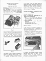 4
4
-
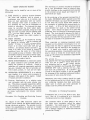 5
5
-
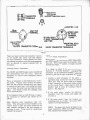 6
6
-
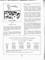 7
7
-
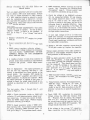 8
8
-
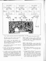 9
9
-
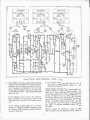 10
10
-
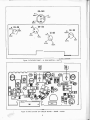 11
11
-
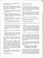 12
12
-
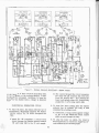 13
13
-
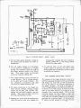 14
14
-
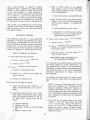 15
15
-
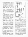 16
16
-
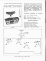 17
17
-
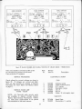 18
18
-
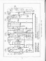 19
19
-
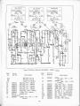 20
20
-
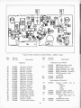 21
21
-
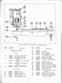 22
22
-
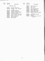 23
23


in altre lingue
- English: Chevrolet 985447
Altri documenti
-
 Beha-Amprobe AT-7030-EUR Manuale utente
-
Crown IC-150 Manuale utente
-
Realistic MG-1 Manuale utente
-
-
HP 1123A Manuale utente
-
-
Tektronix PG 502 Manuale utente
-
Technics SA-GX530 Manuale utente
-
-
Pioneer SX-3400 Manuale utente
