Rockford Fosgate Punch P16 Installation & Operation Manual
- Categoria
- Altoparlanti per auto
- Tipo
- Installation & Operation Manual
Questo manuale è adatto anche per

u
N
c
p
1
P132
•
P142
•
P152
P16
•
P165
•
P1675
P1572
•
P1462
•
P1683
P1692
•
P1694
Serial
Number:
_____
_
Date
of
Purchase:
____
_
Installation
&
Operation

Dear
Customer,
Congratulations
on
your
purchase
of
the
world
's
finest
brand
of
car
audio
amplifiers.
At
Rockford
Fosgate
we
are
fanatics
about
musical
reproduc-
tion
at
its
best
,
and
we
are
pleased
you
chose
o
ur
product.
Through
years
of
engineering
expertise
,
hand
craftsmanship
and
critical
testing
procedures
,
we
have
created
a
wide
range
of pr
oducts
that
reproduce
music
with
all
the
clarit
y
and
richness
you
deserve.
For
maximum
performance
we
recommend
you
have
your
new
Rockford
Fosgate
product
installed
by
an
Authorized
Rockford
Fosgate
Deale
r,
as
we
provide
specialized
training
through
Rockford
Technical
Tr
a
ining
Institute
(RTTI)
.
Please
read
your
warranty
and
retain
your
receipt
and
original
cart
on tor
possible
future
use
.
Great
product
and
competent
installations
are
only
a
piece
of
the
puzzle
w
hen
it
comes
to
your
sy
stem
Make
sure
that
your
installer
is
using
100
%
authentic
installation
accessories
from
Rockford
Fosgate
in
y
our
installation.
Rockford
Fosgate
has
everything
from
RCA
cables
and
speaker
wire
to
po
w
er
w
ire
and
batter
y
connectors.
Insist
on
it!
After
all
,
your new s
ys
tem
deserves
nothing
but
the
best
.
To
add
the
finishing
touch
to
your
new
Rockford
Fosgate
image
orde
r
your
Rockford
accessories
,
which
include
everything
from
!-shirts
to
jackets.
Visit
our
web
site
for
the
latest
information
on
all
Rockford
products
;
www.
rockfordfosgate
.com
or,
in
th
e U S
ca
ll1
-8
00
-6
69
-
9899
or
FAX
1-8
00-
398
-3985.
F
or
al
l
o
th
er
countries,
call
+001-480-967-3565
or
FAX
+00
1
-480-966-3983.
Table
of
Content
2
Introduction
3-7
Specifications
8-11
Installation
In
s
tallation
Consider
at
ion
s
Moun
tin
g
12-15
Additional
Languages
Fr
ench
S
pani
sh
Ge
rm
an
It
al
ia
n
16
Limited
Warranty
Information
If,
after
re
adi
ng
you
r
manual
,
y
ou
st
ill
have
que
s
tion
s
regar
ding
th
is pr
od-
uct
, we
recom
mend
th
at
yo
u see
your
Rockford
F
osg
at
e
dea
ler.
If
you
ne
ed
further
as
sista
nce,
you
can
ca
ll us d
irect
at
1-800-669-9899.
Be
sure
to
have
yo
ur
ser
ial
number
,
mod
el
num
ber
and
da
te
of
purc
hase
availabl
e
wh
en
you
ca
ll.
PRACTICE
SAFE SOUND
Conti
nuo
us
exposure
to
sou
nd pre
ssure
levels
o
ver
1
OO
dB
may
cause
perm
anen
t
heanng
loss.
Hi
gt1
po
wered
auto
so
und sys
tems
rnay
produ
ce
so
und
pressure
le
vels
we
ll
ove
r
130d8.
Use
com
mon
sens
e
an
d
fJ
r
ac
tl
ce
sa
fe
so
u
nd.
PRATIQUEZ UNE
ECOUTE SANS RISQUES
Une
ex
po
si
t
ion
continue
a
des
n
iv
ea
ux
de
pression
ac
o
us
tiq
ue
uperieur
s
a
100
dB
p
eut
causer
une
perte
d'
ac
u
it
e
auditive
pe
r
ma
n
ente
.
Les
systernes
au
di
o
de
forte
puissance
p
ou
r au
to
peuvent
produir
e d
es
ni
veaux
de
pres
sion
aco
ustique
bien
au-
dela
de
130
dB.
Fait
es
p
reuv
e de
bon
sens
et
pratique
z une
ec
ou
te
sans
ri
s
ques
PRACTIQUE EL
SONIDO SEGURO
El
co
ntacto
continuo
con
n1veles
de pr
es
ion
de
so
n
id
o s
up
e
ri
ores
a
i
00
dB
p
uede
c
aus
ar
Ia
per
did
a
perrna
n
en
te
de
Ia
a
udi
ci
on.
Lo
s
si
st
ema
s de
soni
do
de
alta
palencia
para
au
to
m6viles
pueden
prod
uw
nive
le
s
de
presion
de
sonido
superio
re
s a l
os
130
dB.
Aplique
el
sen
ti
do
co
rnun
y
prac
t
ique
ei
so
nido
seguro
PRAKTIZIEREN SIE SICHEREN SOUND
Fort
ge
set
zt
e Ger
ausch
dru
ck
pe
ge
l von
uber
10
0
dB
k
iin
nen b
eirn
Men
schen
zu
perma
n
en
tem
H6
rve
rl
us
t
flihr
en.
Leis
tu
ng
sst
ar
ke
Autoso
u
nds
yst
e
me
kiinnen
Ger
ausc
hdru
ck
peg
el erz
eugen
, die
we
it [Jber
130
dB
li
e
gen
.
Bitte
wen
den
S
ie
ge
sunde
n
Mens
c
hen
verst
and
an
und
prakt
iz
i
eren
Sie si
cll
er
en
Soun
d.
OSSERVATE
LE
REGOLE
DEL
SUONO
SENZA
PERICOLI
La costa
nt
e
es
po
si
z
ione
a
liv
el
li di p
ressi
on
e ac
us
t
ica
al
di
sopra
de
i
1
OOd
B
pos
so
no
causare
Ia
per
di
ta
p
ermane
nt
e
dell
'
ud
i
to
.
I
si
s
terni
aud
io
ad
alta
pot
enz
a
possono
prod
ur
re
l
ive
lli
di
press
i
one
acus
tica
ben
supe
riori ai
130d
B.
S1
co
nsi
gl
ia
il
b
uon
se
nso e
l
'osserva
n
za
delle
re
go
ie
del
s
uo
no
se
nz
a
pericol
i
Safety
This
sy
m
bol
wi
th "
WARNING
"
is
int
e
nd
ed
to
alert
the
user
to th
e
pr
esence
of
imp
or
t
an
t
instru
ct
i
ons.
Fa
ilu
re
to
h
eed
the
ins
truc
ti
ons
will
re
s
ult
in
s
evere
injury
or
de
ath.
Thi
s
sym
bo
l
with
"C
AU
TION"
is
inte
nd
ed to
&WARNING
a
lert
th
e
use
r to t
he
pr
ese
n
ce
of
imp
o
rt
a
nt
~
in
st
r
uct
i
ons.
F
ai
lu
re
to
heed
t
he
i
ns
tru
c
tion
s
ill
CAUTION
ca
n r
es
ul
t
in
inju
ry
or
unit
dam
age.
•
To
pr
eve
nt
i
njury
a
nd
d
amage
to
th
e
un
i
t,
pl
ease
r
ead
and
fo
ll
ow
the
instru
ctio
ns in
th
is
m
anua
l.
We
w
an
t
you
to
en
j
oy
this
sys
tem,
no
t
get
a h
eadac
he.
•
If
you
fee
l
unsu
re
abo
ut
i
nstal
ling
th
is
system
you
rself,
have
it
ins
t
al
l
ed
by
a
q
ua
li
fi
ed
Rockfo
rd
Fosga
te t
ec
hni
ci
an.
•
Befo
re
ins
t
al
la
ti
on,
di
sconne
ct
th
e
batte
ry n
egat
i
ve
(-)
ter
m ina I
to
pr
ev
ent
da
m
age
to
the
u
ni
t,
fire an
d/o
r
poss
ibl
e
injur
y.

~~
i:p(}
E
;
i
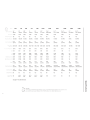
P132
P142
P152
P16
P165
P1675
P1462 P1572
P1683
P1692
P1694
3.5
"
4.0"
5.25"
6"
6.5"
6.75
" 4" X 6"
5"
X
7"
6"
X 8"
6"
X 9" 6" X 9"
(89mm)
(102mm
)
(133mm)
(152mm)
(165mm
) (
17
1.5mm)
(102x152mm)
(
127
x 1
78mm
)
(15
2 x
203mm
)
(1
52
x
229mm
) (
152
x
22
9m
m)
2-Way
2-Way
2-Way
2-Wa
y
2-Way
3-W
ay
2-Way
2-
Way
3-Wa
y 2-
Way
4-Wa
y
N(n:
:
nai
impp,ct~H
~
Cb
4Q
4Q
4Q
4Q
4Q
4Q
4Q
4Q
4Q
4Q 4Q
Hc::ne:r:~e
120-22kHz
100-22kH
z
70-22kHz
65
-22kHz
65-22
k
Hz
60-24kHz
9
0-22kH
z 75-
22
k
Hz
65-24
kH
z .
60
-
22
kHz
60-2
4kH
z
0.
75"
10"
1.0"
10"
1.0"
1
.0"
1.0
"
1.0
" 10" 10"
1.
0"
(20mm)
(25.4mm
)
(25.4mm)
(25.4m
m)
(25.4mm
)
(25
4mm)
(25
4
mm
)
(25.
4m
m)
(2
54m
m)
(2
5
.4m
m)
(
25
.4
mm
)
Pcwcr
20W
I
40W
(H;
\
1
:)/P(.:;:~k
}
30W
/60W
40W
/BOW
55W
I 1
10W
55W
I
11
0W
60W
I
120W
35W
/
?OW
60W
I 1
20W
65W
I 1
30W
75W
I
150W
75W
I 1
50W
F~-
12
0
Hz
100Hz
70Hz
65Hz
65Hz 60Hz
90Hz
75Hz
65Hz
60
Hz
60Hz
Jrs
0.60
0.80 0.68 0.68
0.68
0.
68
0.
80
0.68
100
0.7
2 0.
72
\h
•' 0.
03
fP
0.09fP
0.19fP
0.
60
fP
0.60fP
0.
60
fP
0.
08
fP 0.
19fP
0.48
ft
3
0
.78ft
3
0.78
ft
3
'"'
(0.9L)
(2
5L)
(5.4L)
(16.8L)
(16.8L
)
(168
L)
(2
.2L)
(5.4L
)
(13.6L)
(
22
.0L)
(22
.0L
)
t!'N'
lM)
85
dB
86.5dB
87dB 88dB
88dB
89dB
8
7.
5dB
89dB
90dB
91dB 91dB
88
dB
89.5dB
90dB
91d
B
91dB 92dB
90
.
5dB
92dB
93dB
94
dB
94
dB
X 0.04"
0.06
"
0.08"
0.
14
"
0.14"
0.1
4"
0.08"
0.08
"
0
.14"
0.
18
" 0.18"
m
ax
(1.0mm)
(15mm)
(20mm)
(3.5mm
)
(35mm)
(3.5
mm)
(2.0
m
m)
(2.0mm)
(3
.5mm)
(4.5
mm
)
(4.5mm)
\i
li"
C
C'
3.
21"
4.04"
4.81
"
5.05
"
5
.05
" 5.
68"
3.76
"
x6.01
"
4.76"x7.0
2"
5.
08
"
x7.26
" 5.
77"x8
.
51
"
5.77"x8
.51"
rd
..
,Jv.
(816mm)
(1025mm)
(1
22.2m
m)
(1
282mm)
(128
2mm)
(1
442mm)
(95
6x
1
52
.
6mm)
(1
20
.
9x
17
8.4
mm)
(1
29.
0x
1
84.3
mm)
(1
46
5
x2
1
6.
2
mm
)
(146
.5x2
16
.2
m
m)
•
""
1.46"
1.75"
1.91"
1.93
"
193
" 2.
24"
1.89
"
2.30
"
2.32"
3.
0
7"
3.
07"
uer
;r;;
(37
.
0mm)
(44
Smm)
(48.5mm)
(49.0mm)
(49.0mm
)
(57
.
0mm)
(4B
.
Omm
)
(SB
.S
mm)
(59.0m
m)
(7
B.Omm
)
(78
.0
mm
)
Gr
i!
i
e/Tnm
Fiinu
NO
NO
YES
YES
YES
YES NO
NO
NO
Y
ES
YES
P!aie
NO
4
"x6"
I
5"x7"
I S"
x7"
I
S"xT'
I
5"
xT'
I
6"
x8
" 6"
x8"
NO
NO
NO
6"x8"
6"x9"
6"
x9
"
6"x9"
6"
x9"
See
pages
4-7
for
addition
al di
mensions.
en
"0
CD
0
~
0
~···
·
"~s'•
•""
CEA 2
006
Q)
.....
-1
~
""
0
L
"'
Po
w
er
ra
ti
n
gs
on
Rock
for
d
Fosg
ate
am
p
li
fi
ers
con
fo
rm
to
CEA
-2
00
fi
industry
stan
dard
s.
Th
e
se
gu
i
delines
:
nea
n
0
'::;.
2
031
~
.
/
your
ampl
if
ier
's ou
tp
ut
power
ra
t
ings
are RE
Al_
POWEF1
n
um
bers, not i
nflat
ed m
arke
ti
ng
ra
ti
no
s.
::s
en
w

Specifications
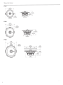
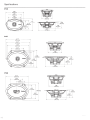
P132
P142
P152
4
5
43"
(13B.Omm)
Diameter
'
u::
,
-;'

P16jP165
6.69"
(170.0mm)
Diameter
P1675
6.7
7"
{172.0mm)
4.37"
(111.0mm)
6.10"
(155.0mm)
""'""',.....
·
' Diameter
5.59"
(142.0mm)
Diameter
6.18"
(157.0mm)
Diameter
6.89"
r-
----
(175.0mm)
I
~
w
I
0
1-----
-
5.05"
(128.2mm)
6.97"
(177.0mm)
sv
5.68"
1---
---
(144.2mm)
- -
--j
0.94"
~
sl
(23.8mm)
,
=r
Specifications
ill
u
s.
-'
2
5

6
Specifications
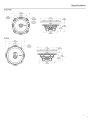
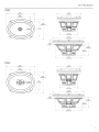
P1462
P1572
I
•
(22~~~m)
~
8.27"
'-
1
•
-----
(210.0mm)
7.88"
'------
(200.1mm) -
P1683
8.10"
(205.8mm)
I
!
fi
5.68"
I
5
.0~':44.2mm)
(127.6mm)
3.54"
(110.6mm)
5.90"
(149.8mm)
5.04"
(12
7.
9mm)
7.02"
(1
78.4mm)
5.08"
---1
(129.0mm)
7.26"
(184.3mm)
2.
87"
(72.9mm)
2.32"
(59.0mm)

P1692
P1694
9.37"
(238.0mm)
----~
6.60"
(167.7mm)
--
----1
-1
6.61"
(168.fmm)
4.78"
(121.5mm)
I
6.61"
(168.0mm)
7.
56"
(192.0mm)
!
r-----
5.77"
(146.5mm)
10.24"
(260.0mm)
8.
51"
(216.2mm)
8.
5
1"
(216.2mm)
Specifications
----
3.53"
(89.6mm)
3.07"
(78.0mm)
I
f
3.53"
(89.6mm)
7

8
Installation
Contents
•
(1)
Pair
Punch
Series
Full
Range
Speakers
•
(1)
Pair
of
grilles/trim
rings
(P152,
P16
,
P165,
P1675
,
P1692
and
P1694
only)
•
(1)
Pair
of
5x7
adapter
plates
(P142,
P1462,
P1572
only)
•
(1)
Pair
of
6x9
adapter
plates
(P152,
P16,
P165,
P1675
only)
•
Mounting
Hardware
Installation
Considerations
Before
beginning
any
installation
,
follow
these
simple
rules:
1.
Be
sure
to
carefully
read
and
understand
the
instructions
be
f
ore
attempting
to
install
the
se
speake
rs.
2.
For
safety,
disconnect
the
negative
lead
from
the
battery
prio
r
to
beginning
the
installation.
3.
For
easier
assembly,
we
suggest
you
run
all
wires
prior
to
moun
t
ing
your
speakers
in
place
.
4.
Use
high
quality
connectors
for
a re
liable
installation
a
nd
to
minimize
signal
or
power
loss.
5.
Think
before
you
drill!
Be
careful
not
to
cut
or
drill
into
gas
tanks
,
fuel
lines,
brake
or
hydraulic
lines,
vacuum
line
s
or
electrical
wiring
when
working
on
any
vehicle.
If
installation
in
a
boat,
take
ca
re
not
to
cut
or
drill
through
the
main
hull.
6.
Never
run
wires
underneath
the
vehicle.
Running
the
wires
insid
e
the
vehicle
or
hull
area
provides
the
best
protection.
7.
Avoid
running
wires
over
or
through
sharp
edges.
Us
e
rubber
or
plastic
grommets
to
protect
any
wires
routed
through
metal,
es
p
ec
i
al
ly
the
firewall.
Mounting
1.
Determine
where
the
speakers
will
be
mounted
.
Ensure
an
area
large
enough
for
the
speaker
to
mount
evenly
Be
su
re
that
the
mounting
location
is
deep
enough
for
the
speaker
to
fit;
if
mounting
in
a
door,
operate
all
fun
c
tions
(windows,
locks
,
etc.)
through
their
en
tire
operating
range
to
ensure
there
is
no
obstruction.
2.
Ref
er
to
the
spec
ification
chart
to
determine
the
proper
di
ame
ter
hole
to
cut
for
your
speaker
model.
Cutting
and
mounting
templates
can
be
found
at
www.rockfordfosgate.com.
3.
Mark
the
l
ocations
for
the
mounting
scre
ws.
Drill
the
holes
with
a
1/8
"
bit.
4.
Fe
ed
the
speaker
wires
through
the
cutout
a
nd
connect
to
the
speaker
terminals.
Be
su
re
to
observe
proper
polarity
when
connecting
th
e
wire
s.
The
s
peak
er's
positive
terminal
is
indicated
with
a"+".
5.
On
models
with
slotted
holes,
fit
the
speaker
in
to
the
cutout
and
install
t
he
screws
in
the
slo
ts
at
the
top
and
bottom.This
will
allo
w
you
to
rotate
the
speaker
to
match
the
remai
ning
mount
ing
holes
.
Whe
n
aligned,
tighten
the
screws.
OR
6.
On
models
with
a
trim
ring
,
fit
the
trim
ring
over
the
speaker
and
mount
into
place
using
four
(4)
screws.
7.
Tig
h
te
n
the
screws
until
the
speaker
is
snug
in
pl
ace
to
prevent
rattling.
Do
not
over
tight
en
the
screws.
NOTE:
For
P142,
P1462,
P152
,
P
16,
P165
and
P167
5
only,
if
needed
use
the
adapter
plate
provided
to
mount
the
speaker.
See
Adapter
Plate
Templates
.
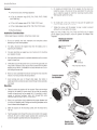
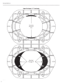
Mounting
tab
removal
for
some
installations
\;
\
,,
p \
••
!
' ; I
0
U
se
plieo
to
brro
k
o
ff
#-
~i
.. ·.·
.;·
··.. ,
plast1ctab
'
~
~
..
~
\,~
..
:
'
Example
of
standard
door
installation
i.
i
';
;
~
f.)
Breakoff
mount
ing
tab.
*
P142
,
P15
2,
P16
&
P1
65
Onl
y
.
· ·
~~
~·
·>
.
.t
o
Align
Holes
.. ·
.
··
.,.
..
........ .
Example
of
rear
deck
installation

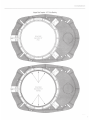
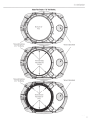
Adapter
Plate
Template·
6.75
"
Hole
Mounting
Remove
Sha
d
ed
Areas
to
Mount
5.25"
(P
152)
Remove
Shaded
Areas
to
Mo
u
nt
6"/6.5"
(P
1
6/P
1
65)
~t;~ll
ion
9

Installation
10
Adapter
Plate
Template
-5"
x7
"
Hole
Mounting
Remove
Shaded
Ar
eas
to
Mou
nt
4"
(P142)
Remove
Shaded
Areas
to
Mount
4"
x6"
(P1462)

Adapter
Plate
Template·
6"x9"
Hole
Mounting
Mo
u
nt
ing
fo
r 5.
25"
(P1
52)
fnstaUation
*Remov
e
for
Optional
Tw
eeter
11

12
Considerations
Concernant
L'installation
Avant
de
commencer
l'installation,
suivez
les
regles
ci-dessous:
1.
Veillez
a
bien
lire
et
comprendre
les
instructions
avant
d'essayer
d'inst
a
ller
les
haut
-
parleurs
.
2.
Par
mesure
de
securite,
debranchez
le
til
negatif
de
Ia
batterie
avant
de
commencer
!'installation.
3.
Pour
taciliter
le
montage
des
haut-parleurs,
il
est
conseille
d'ins
ta
ller
to
us
les
cables
au
prealable.
4.
Utilisez
des
connecteurs
de
haute
qualite
pour
assurer
une
installation
liable
et
reduire
au
minimum
Ia
perle
de
signal
ou
de
puissance.
5.
Reflechissez
bien
avant
de
percer.Veillez
a
ne
pas
couper
ou
percer
le
reservoir
d
'es
sence,
le
cab
lage
electrique
ou
les
conduites
de
carburant,
de
freinage
hydraulique
ou
de
depression
en
tr
availla
nt
sur
un
vehicule.
En
cas
d'installation
sur
un
bateau,
veillez
a
ne
pas
couper
ou
percer
Ia
coque
principale.
6.
Ne
jamais
faire
passer
de
fils
sous
le
ve
hicule.
Leur
installat
io
n a
l'interieur
du
vehicule
ou
de
Ia
co
que
assure
Ia
meilleure
prote
ct
ion.
7.
Evitez
de
faire
passer
des
fils
s
ur
des
bords
tranchants
ou
dans
des
orifices
a
aretes
vives.
Utilisez
des
bagues
en
caou
tch
ouc
ou
en
plastique
pour
proteger
les
fils
traversant
une
plaque
de
metal,
notamment
le
tablier.Emplacements
De
Montage
Montage
1.
Determinez
!
'e
mplacement
des
haut
-
parleurs.Veillez
a
ce
que
Ia
surface
plane
soil
assez
gr
ande
pour
assurer
un
contac
t
uniforme
du
haut-parleur
.V
er
ifi
ez
que
!
'emp
lac
ement
est
assez
profond
pour
le
haut-parleur
;
en
cas
de
montage
dans
une
portiere,
actionne
z
toutes
les
commandes
(fenetres,
serrures,
etc.)
jusqu
'a
ux
extremites
de
leurs
courses
pour
vou
s
assurer
qu'il
n'y
a
pas
d'obstruction.
2.
Consultez
le
tableau
des
carac
teri
s
tique
s
pour
determiner
le
diametre
de
!'orifice
a
decouper
pour
votre
modele
de
haut
-
parleur.
Le
gabarit
fourni
donne
aussi
le
bon
diametre
de
decoupe.Les
gabarits
de
coupe
et
de
montage
sont
disponibles
sur
Ia
page
www.rockfordfosgate
.
com/rftech.
3.
M
arquez
!'
emp
l
acement
des
vi
s
de
montage.
Percez
l
es
trous
avec
une
meche
de
1/8
de
pouce
(
3,2
mm).
4.
Fa
ite
s
passer
le
s
fils
de
ha
ut-p
ar
leur
a t
ravers
!
'orifice
decoup
e
et
branchez-les
aux
barne
s
du
haut-parleur.Veillez
a
bien
re
specte
r
Ia
polarite
lors
du
branchement.
La
borne
positive
du
haut-parl
eu
r
est
indiquee
par
un
" + ''·
5.
Surles
modeles
a
trou
s a
ll
onges,
mettez
le
haut-parleur
en
place
dans
Ia
decoupe
et
in
sta
ll
ez
l
es
vis
dans
les
trous
du
haul
et
du
bas.Vous
pourre
z al
or
s
fa
i
re
tourner
le
haut-parleur
pour
!
'a
lign
er
s
ur
l
es
au
tres
trous
de
montage
Une
lois
ce
t
alignement
effectue,
serrez
les
vis.
ou
6. S
ur
les
modeles
a
anneau
de
garniture
, p
lac
ez
celui-ci
s
ur
le
h
aut-
parleur
et
fi
xe
zle
avec
quatre
vi
s.
7.
Serrez
les
vis
jusqu'a
ce
que
le h
aut-parleur
so
it
bi
en
aj
uste,
de
lagon
a
prevenir
tout
cliquetis,
ma
is
ev
i
tez
tout
serrage
excessif.REMAROUE:
Nous
recommandons
!'
utilisation
d'un
Iii
de
4AWG
pour
les
prises
d'alimentation
(B+)
et
de
masse
(GND).
Prepare
z
le
til d'al
imentation
ROUGE
a
conn
ecter a
l'amplificateur
en
de
n
udan
t
so
n
extremite
sur
13
mm.
lnsere
z
Ia
partie
denu
d
ee
da
ns
Ia
borne
B+,
puis
fi
xe
z le
fil
en
vissant
Ia
vis
sa
ns
tete
.
REMARQUE:
Pour
les
modeles
P142,
P1462,
P152,
P16
,
P165
et
P1675
seulement
, u
tilisez
si
necessai
re
Ia
plaque
d'adaptati
on f
ournie
pour
mant-
er
le
haut-parleur.Voir
les
gabari
ts
de
plaque
d'adaptati
on
.

Consideraciones
para
Ia
instalacion
Antes
de
comenzar
cualquier
instalaci6n,
siga
estas
simples
normas
:
1.
1.
Asegurese
de
leer
cuidadosamente
y
de
entender
las
instrucciones
antes
de
tratar
de
instalar
estos
altavoces.
2.
Par
seguridad,
desconecte
el
conductor
negative
de
Ia
baterfa
antes
de
comenzar
Ia
instalaci6n.
3.
Para
facilitar
el
montaje,
sugerimos
que
tienda
todos
los
cables
antes
de
montar
sus
altavoces
en
su
sitio.
4.
Uti
lice
conectores
de
alta
calidad
para
tener
una
instalaci6n
confiable
y
para
reducir
al
mfnimo
las
perdidas
de
serial
ode
palencia.
5.
iPiense
siempre
antes
de
perforar!
Tenga
cuidado
de
no
cortar
ni
perforar
en
tanques
de
combustible,
tuberfas
de
combustible
,
frenos
o
hidr
au
licas
,
tuberfas
de
vacfo
o
cableado
electrico
al
trabajar
en
un
vehfculo.
Si
Ia
instalaci6n
se
hace
en
un
bote,
tenga
cuidado
de
no
cortar
ni
perforar
a
!raves
del
casco
principal.
6.
Nunca
tienda
cables
abajo
del
vehfculo.Tender
los
cables
adentro
de
l
vehfculo
o
casco
proporciona
Ia
mejor
protecci6n.
7.
Evite
tender
cables
arriba
o a
!raves
de
bordes
filo
sos
.
Use
arandelas
aislantes
de
caucho
para
proteger
lo
s
cables
tendido
s a
trave
s
de
metal,
especialmente
Ia
mampara
cortafuegos.Montage
Montaje
1. D
ete
rmin
e
ad6nde
se
montara
los
altavoces
.
Asegurese
de
que
haya
un
a
re
a
suf
i
cien
tem
en
te
grande
para
montar
de
manera
plana
el
altavoz
.
Asegure
se
de
que
el
Iugar
de
montaje
sea
suficientemente
profunda
para
que
quepa
el
altavoz,
si
se
manta
en
una
puerta,
accione
todas
las
funciones
(ventanas,
cerradura,
etc.)
en
toda
su
gama
de
funcionamiento
para
asegurarse
de
que
no
haya
obstrucciones.
2.
Consulte
Ia
tabla
de
especificaciones
para
determinar
cuales
son
los
diametros
correctos
para
el
agujero
a
co
rt
ar
para
su
model
o
de
altavoz.
La
plantilla
proporcionada
tambien
le
da
Ia
medida
correc
ta
del
recorte.Se
puede
hall
ar
las
plantillas
para
el
corte
y
el
montaj
e en
www.rockfordfosgate.com/rftech.
3.
Marque
la
s
localidades
para
lo
s
tornill
os
de
montaje.
Perfore
lo
s
agu
jero
s
usando
una
brocade
1/8
pulg.
4.
Tienda
lo
s
cables
del
altavoz
a
!rav
es
del
recorte
y
conecte
a
los
terminales
del
altavoz.Asegurese
de
usar
Ia
polaridad
correcta
al
co
nectar
los
cables.
El
terminal
positive
del
altavoz
esta
identific
ado
con
un
sf
mbolo
"+"
.
5.
En
los
modelos
con
agujeros
r
anurados,
co
loqu
e el a
ltavo
z
en
el
recorte
e
instale
lo
s
tornillos
en
las
ranuras
en
Ia
parte
s
up
er
i
or
e
inferior.
E
sto
le
permitira
hacer
g
ir
ar
el a
ltavo
z
para
que
coinci
da
con
l
os
agu
jer
os
de
montaje
restante
s.
Un
a
vez
alineados,
apriete
los
tornillos.
0
6.
En
los
mod
el
os
co
n
un
an
illo
de
acabado,
coloque
el
an
illo
de
Espanoi
acabad
o
arriba
del
altavoz
y
m6ntelo
en
su
sitio
usando
cuatro
(4)
torni
l
lo
s.
7.
Apriete
los
tornillos
hasta
que
el
altavoz
este
ajustado
en
su
sitio
para
evitar
vibraciones.
No
apriete
demasiado
los
tornillos.
NOTA:
Si
es
necesario,
solo
para
P14
2,
P1462,
P152,
P16
,
P165
y
P1675,
use
Ia
placa
adaptadora
proporcionada
para
montar
el
a
ltavoz
.
Consulte
las
plantillas
de
las
placas
adaptad
ora
s.
13

14
Deu
ts
ch
Einbauiiberlegungen
Befolgen
Sie
vor
dem
Einbau
diese
einfachen
Regeln:
1.
1.
Lesen
Sie
die
Anleitung
sorgtaltig,
bevor
Sie
versuchen
diese
Lautsprecher
einzubauen.
2.
Entfernen
Sie
vor
dem
Einbau
aus
SicherheitsgrUnden
das
negative
Kabel
von
der
Batterie.
3.
Um
die
Montage
zu
erleichtern,
empfehlen
wir
aile
Kabel
vor
der
Befestigung
lhrer
Lautsprecher
zu
verlegen.
4.
Verwenden
Sie
nur
Qualitatsstecker,
um
einen
zuverlassigen
Einbau
zu
gewahrleisten
und
Signal-
und
Stromverlust
zu
minimieren.
5.
Denken
Sie
nach
,
bevor
Sie
bohrenl
Achten
Sie
darauf,
nicht
in
den
Benzintank,
die
Benzin-,
Brems-
oder
hydraulischen
Leitungen,Vakuumleitungen
oder
Elektrokabel
zu
schneiden
oder
zu
bohren,wenn
Sie
am
Fahrzeug
arbeiten.Achten
Sie
beim
Einbau
in
einem
Boot
darauf
,
nicht
durch
den
Bootsrumpf
zu
schneiden
oder
zu
bohren.
6.
Verlegen
Sie
Kabel
nie
unter
dem
Fahrzeug.
Die
Kabel
im
Fahrzeug
oder
Bootsrumpf
zu
verlegen,
bietet
den
besten
Schut
z.
7.
Vermeiden
Sie
es,
Kabel
Uber
scharfe
Kanten
zu
verlegen.Verwenden
Sie
Gummi-
oder
Plastikringe,
um
Kabel
zu
schUtzen,
die
durch
Metal
I
verlegt
werden
(besonders
die
Feuerwand).
Befestigung
1.
Entscheiden,wo
die
Lautsprecher
befestigt
werden
sollen
.
Gewahrleisten,
dass
der
Platz
ausreicht
,
um
den
Lautsprecher
gleichmaBig
zu
betestigen.
Gewahrleisten,
dass
die
Betestigungsstelle
ausreichende
Tiefe
fUr
den
Lautsprecher
hat;
beim
Einbau
in
einer
TOre
aile
Funktionen
(Fenster,
Schloss
usw.)
in
ihrem
ganzen
Bereich
ausprobieren
um
zu
gewahrleisten,
dass
keine
Blockierung
eintr
i
tt.
2.
Die
Tabelle
in
den
Technischen
Daten
gibt
den
richtigen
Lochdurchmesser
fUr
lhr
Lautsprechermodell
zum
Ausschneiden
an.
Die
beiliegende
Schablone
zeigt
ebenfalls
die
richtige
AusschneidegroBe
an.Schneide-
und
Befestigungsschablonen
linden
Sie
unter
www.rockfordfosgate
.
com/rttech
.
3.
Die
Stellen
fUr
die
Befestigungsschrauben
markieren.
Die
Loche
r
mit
einer
1/8
-
Zoll
(3,2
mm)
Bohrerspit
ze
boh
r
en.
4.
Die
Lautsprecherkabel
durch
das
Loch
tuhren
und
an
den
Lautsprecherausgangen
anschlieBen
.
Beim
AnschlieBen
der
Kabel
die
ordnungsgemaBe
Polaritat
beachten
.
Der
positive
Anschluss
des
Lautsprechers
ist
mit
einem
,+"
markiert.
5.
Bei
Modellen
mit
geschlitzten
Lochern
den
Lautsprecher
in
das
Loch
einpa
ss
en
und
die
Schraub
en
in
den
Schlit
ze
n
ob
en
und
unten
befe
s
tigen
.
Dadurch
konnen
Sie
den
Lautsprecher
so
drehen
,
das
s
die
Ubrigen
Befe
s
tigungslocher
passen.
Nach
der
Ausrichtung
die
Schrauben
an
z
iehen.
ODER
6.
An
Model
len
mit
einem
Zie
rr
i
ng
den
Zierring
Uber
den
Lautsprecher
legen
und
mit
4
(vier)
Schrauben
an
seinem
Platz
befestigen.
7.
Die
Schrauben
anziehen,
bis
der
Lautsprecher
eng
an
seinem
Platz
anliegt
,
um
Klappern
zu
verhindern.
Die
Schrauben
nicht
zu
fest
anziehen.
HINWEIS:
Falls
erforderlich
die
beiliegende
Adapterplatte
bei
der
Befes-
tigung
des
Lautsprechers
verwenden
(nur
bei
P142,
P1462,
P152,
P16,
P165
und
P1675).
Siehe
Adapterplatten-Schablonen.

Considerazioni
sull'installazione
Prima
di
iniziare
qualsiasi
operazione
d'installazione,
vi
consigliamo
di
seguire
queste
semplici
regale:
1.
Assicuratevi
di
aver
letto
tutte
le
istruzioni
con
cura
e
di
averle
capite
prima
di
effettuare
qualsiasi
tentative
d'
i
nstallazione
neiconfronti
dell'unita.
2.
Per
motivi
di
sicurezza,
scollegate
il
cava
negative
dalla
batteria
pr
i
ma
di
dare
l'avvlo
all'installazione.
3.
Per
facilitare
il
montaggio,
vi
suggeriamo
di
far
scorrere
tutti
i f
ili
prima
di
montare
Ia
vostra
unita
nella
sua
ubicazione.
4.
Usate
connettori
di
alta
qualita
per
garantire
un'installazione
che
da
affidamento
e
per
ridurre
al
minima
Ia
perdita
di
segnali
o
di
potenza
.
5.
State
attenti
prima
di
trapanare!
Cercate
di
non
trapanare
e
di
non
incidere
i
serbatoi
della
benzina;
le
condutture
del
carburante
,
dei
freni,
del
sistema
idraulico
e a
depressione;
nonche
i
fili
elettrici
quando
state
lavorando
su
qualsiasi
veicolo.
6.
Non
fate
mai
scorrere
i
fili
sotto
il
veicolo.Av
r
ete
Ia
protezione
migl
io
re
faccendo
scorrere
i
fili
all'interno
del
vei
co
lo.
7.
Evitate
di
far
scorrere
i
fili
sopra
o
attraverso
delle
estremita
affilate
.
Usate
guarnizioni
di
tenuta
in
gamma
o
in
plastica
per
proteggere
qualsiasi
fila
che
passi
attraverso
del
metallo,
soprattutto
il
parafiamma.
Montaggio
1.
Decidete
dove
montare
gli
altoparlanti.Assicuratevi
che
sia
un'area
abbastanza
grande
per
pater
montare
l'altoparlante
a
liveflo
e
abbastanza
profonda
per
poterlo
collocare
comodamente.
Se
lo
montate
all'interno
di
uno
sportello,
controllate
tulle
le
funzioni
(finestre
,
serrature,
ecc
.
),
una
alia
volta,
per
assicurarvi
che
non
ci
siano
ostruzioni.
2.
Fate
riferimento
alia
tabell
a
dell
e
specifiche
per
stabilire
il
diam
e
tro
corretto
del
foro
che
dovrete
praticare
per
il
modello
del
vostro
altoparlante.Si
possono
trovare
le
sagome
peril
taglio
e
il
montaggio
presso
www.
rockfordfosgate.com/rftech.
3.
Marcare
le
posizioni
perle
viti
di
montaggio
.
Praticare
i
fori
con
una
punta
da
trapano
di
1/8
di
pol
lice
(3,2
mm)
.
4.
Passare
i
cavi
del
diffusore
tramite
l'ap
er
tura
e
collegarli
ai
term
ina
li
.
Verificare
che
Ia
polarita
sia
corretta
quando
si
collegano
i
cavi.
II
terminale
positivo
del
diffusore
e
identificato
dal
"+".
5.
Nei
modelli
con
fori
a
slot,
adattare
il
diffu
s
ore
nel
foro
ritagl
ia
to
e
inserire
le
viti
negli
slot
in
alto
e
in
basso
.
Cosl
facendo
si
potra
ruotare
il
diffu
so
re
per
allinearlo
co
n i
rimanenti
fori
di
montaggio
Se
rrar
e le
viti
quand
o si
e
ottenuto
l'
a
llineamento.
OPPURE
6.
Nei
modelli
dotati
di
anello
di
finitura,
adattare
l'anello
sui
diffu
so
re e
montare
in
po
siz
ione
se
rv
e
nd
os
i de
ll
e
quattro
(4)
viti
.
Italiano
7.
Per
evitare
rumore
dovuto
a vi
brazioni
serrare
le
viti
finche
il
diffusore
non
sia
saldamente
in
posizione.
Non
serrare
le
viti
in
modo
eccessivo.
NOTA:
Nel
caso
dei
P142,
P1462,
P152,
P16,
P165
e
P1675
solamente
,
montare
il
diffusore
servendosi,
se
necessaria,
della
pias
t
ra
di
adattamen-
to
in
dotazione.
Vedere
Sagome
per
Ia
piastra
di
adattamento
.
15

16
Warranty
Rockford
Corporation
offers
a
limited
warranty
on
Rockford
Fosgate
products
on
the
following
terms:
Length
of
Warranty
Speakers,
Signal
Processors,
PRIME
and
PUNCH
Amplifiers
-1
Year
POWER
Amplifiers-
2
Years
Any
Factory
Refurbished
Product-
90
days
(receipt
required)
What
is
Covered
This
warranty
applies
only
to
Rockford
Fosgate
products
sold
to
consumers
by
Authorized
Rockford
Fosgate
Dealers
in
the
United
States
of
America
or
its
possessions.
Product
purchased
by
consumers
from
an
Authorized
Rockford
Fosgate
Dealer
in
another
country
are
covered
only
by
that
country's
Distribu-
tor
and
not
by
Rockford
Corporation.
Who
is
Covered
This
warranty
covers
only
the
original
purchaser
of
Rockford
product
purchased
from
an
Au
t
horized
Rockford
Fosgate
Dealer
in
the
United
States.
In
order
to
receive
service,
the
purchaser
must
provide
Rockford
with
a
copy
of
the
receipt
stating
the
customer
name
,
dealer
name,
product
purchased
and
date
of
purchase.
Products
found
to
be
defective
during
the
warranty
period
will
be
repai
r
ed
or
replaced
(with
a
product
deemed
to
be
equivalent)
at
Rockford's
discretion
.
What
is
Not
Covered
1.
Damage
caused
by
accident,
abuse,
improper
operations,water,
theft,
shipping.
2.
Any
cost
or
expense
related
to
the
removal
or
reinstallation
of
product.
3.
Service
performed
by
anyone
other
than
Rockford
or
an
Author
iz
ed
Rockford
Fosgate
Service
Center.
4.
Any
product
which
has
had
the
serial
number
defaced,
altered
,
or
removed.
5.
Subsequent
damage
to
other
components.
6.
Any
product
purchased
outside
the
U.S.
7.
Any
product
not
purchased
from
an
Authorized
Rockford
Fosgate
Dealer.
limit
on
Implied
Warranties
Any
implied
warranties
including
warranties
of
fitness
for
use
and
merchantability
are
limited
in
duration
to
the
period
of
the
express
warranty
set
forth
above.
Some
states
do
not
allow
limitations
on
the
length
of
an
imp
l
ied
warranty
,
so
this
limitation
may
not
apply
.
No
person
is
autho
r
ized
to
assume
for
Rockford
Fo
sgate
any
other
liability
in
connection
with
the
sale
of
the
product.
How
to
Obtain
Service
Contact
the
Authorized
Rockford
Fosgate
Deale
r
you
purchased
this
product
from.
If
you
need
further
assistance
,
call1-800-669-9899
for
Rockford
Cus-
tomer
Service
.
You
mu
st
obtain
an
RA#
(Return
Authorization
number)
to
return
any
prod
u
ct
to
Rockford
Fosgate.
You
are
responsib
le
f
or
shipment
of
product
to
Rockford.
EU
Warranty
This
product
me
ets
th
e c
urrent
EU
warr
a
nty
requirements
,
see
your
Aut
h
orized
dealer
for
detai
ls.

Installation
assistance
availible
at:
RFTECH
www.rockfordfosgate.com/rftech
600
South
Rockford
Drive
•
Tempe,
Arizona
85281
United
States
Direct
:
(480)
967-3565
•
Toll
Free:
(800)
669-9899
ROCKFORDFOSGATE.COM
-
 1
1
-
 2
2
-
 3
3
-
 4
4
-
 5
5
-
 6
6
-
 7
7
-
 8
8
-
 9
9
-
 10
10
-
 11
11
-
 12
12
-
 13
13
-
 14
14
-
 15
15
-
 16
16
-
 17
17


Rockford Fosgate Punch P16 Installation & Operation Manual
- Categoria
- Altoparlanti per auto
- Tipo
- Installation & Operation Manual
- Questo manuale è adatto anche per
in altre lingue
- English: Rockford Fosgate Punch P16
- français: Rockford Fosgate Punch P16
- español: Rockford Fosgate Punch P16
- Deutsch: Rockford Fosgate Punch P16
Documenti correlati
-
 Rockford Fosgate P152-S Manuale utente
-
 Rockford Fosgate Punch FRC3205 Manuale utente
-
 Rockford Fosgate FRC3257 Manuale utente
-
 Rockford Fosgate Punch P152 Installation & Operation Manual
-
Rockford Fosgate P1572 Guida utente
-
 Rockford Fosgate PUNCH PM2T-S Installation & Operation Manual
-
Rockford Fosgate PUNCH PPS8-6 Manuale del proprietario
-
Rockford Fosgate Punch P152-S Installation & Operation Manual
-
-
Rockford Fosgate PRIME R1653 Installation & Operation Manual