MAXA OTA-RHP 35÷450 Manuale del proprietario
- Categoria
- Condizionatori d'aria a sistema split
- Tipo
- Manuale del proprietario

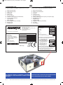
UNITA COMBINATA DI RECUPERO CALORE CON SISTEMA
TERMODINAMICO
COMBINED HEAT RECOVERY UNIT WITH REVERSIBLE HEAT PUMP
SYSTEM
A
IR CONDITI O N I N G
E9
MANUALE UNTENTE-INSTALLATORE
USER-INSTALLER MANUAL
Serie/Series/Serie/Série Emissione/Edition/Au-
sgabeIssue
OTA-RHP 35÷450 01-2021
Sostituisce/Superseedes
Ersetzt/Remplace
Catalogo/Catalogue/Katalog/Brochure
MUI01106E0801-06-

Manuale di Installazione e Manutenzione unità combinata di recupero calore con sistema termodinamico - combined heat recovery unit with reversible heat pump system, use and maintenance manual
pag. 2
IMPORTANTE
PRIMA DI COMPIERE QUALUNQUE OPERAZIONE
RIGUARDANTE LA MACCHINA LEGGERE
ATTENTAMENTE, COMPRENDERE E SEGUIRE
TUTTE LE ISTRUZIONI DEL PRESENTE MANUALE
important
before performing any operation of the
maChine Carefully read,
understand and follow
all instruCtions listed in this manual
1 - SIMBOLOGIA UTILIZZATA ..............................................................3
2 - AVVERTENZE E REGOLE GENERALI ..........................................3
DICHIARAZIONE DI CONFORMITÀ “CE”.............................................5
3 - IDENTIFICAZIONE UNITÀ .............................................................6
4 - CARATTERISTICHE TECNICHE.....................................................7
4.1 Caratteristiche generali................................................................8
4.2 Dati tecnici ...................................................................................9
4.3 Orientamenti possibili ...............................................................10
4.4 Dimensioni e pesi .....................................................................11
4.5 Accessori ...................................................................................12
5 - TRASPORTO ................................................................................18
6 - SCARICO........................................................................................18
6.1 Controllo al ricevimento .............................................................18
6.2 Sollevamento e Movimentazione...............................................18
6.3 Stoccaggio.................................................................................18
7 - INSTALLAZIONE E MESSA IN SERVIZIO ....................................19
7.1 Definizioni ..................................................................................19
7.2 Norme di sicurezza ...................................................................19
7.3 Informazioni preliminari..............................................................20
7.4 Scelta del luogo d'installazione e posizionamento della
macchina ...................................................................................20
7.5 Collegamento alle canalizzazioni ..............................................21
7.6 Collegamenti idraulici.................................................................21
7.7 Installazione accessorio RMS....................................................22
7.8 Collegamento idraulici sezione SBFR .......................................24
7.8.1 Collegamento scarico condensa sezione SBFR .......................24
8 - COLLEGAMENTI ELETTRICI .......................................................25
9 - REGOLAZIONE ELETTRONICA....................................................27
9.1 Controllo elettronico...................................................................27
9.2 Interfaccia utente .......................................................................28
9.3 Programmazione .......................................................................28
9.4 Attivazione ON/OFF remoto o fasce orarie ...............................33
9.5 Gestione della valvola di espansione elettronica ......................34
9.6 Funzionamento in sbrinamento (solo da mod. riscaldamento)..34
9.7 Supervisione (protocollo Modbus RTU).....................................34
10 - CONTROLLI PRIMA DELL'AVVIAMENTO...................................37
11 - MANUTENZIONE ORDINARIA ....................................................37
11.1 Informazioni preliminari..............................................................37
11.2 Controlli con cadenza mensile od inferiore ...............................37
11.3 Controlli con cadenza semestrale .............................................38
11.4 Manutenzione straordinaria .......................................................39
12 - LOCALIZZAZIONE DEI GUASTI..................................................39
12.1 Guida ricerca guasti...................................................................39
12.2 Gestione degli allarmi ................................................................40
13 - SMALTIMENTO............................................................................41
14 - PARTI DI RICAMBIO....................................................................42
1 - SYMBOLS USED .............................................................................3
2 - WARNINGS AND GENERAL RULES ..............................................3
“EC” DECLARATION OF CONFORMITY..............................................5
3 - IDENTIFICATION OF THE UNIT .....................................................6
4 - TECHNICAL SPECIFICATIONS.......................................................7
4.1 General characteristics ................................................................8
4.2 Unit technical data .......................................................................9
4.3 Possible configurations..............................................................10
4.4 Dimensions and weights............................................................11
4.5 Options ......................................................................................12
5 - TRANSPORT..................................................................................18
6 - UNLOADING...................................................................................18
6.1 Checks upon receipt..................................................................18
6.2 Hoisting and handling ................................................................18
6.3 Storage ......................................................................................18
7 - INSTALLATION AND START UP ..................................................19
7.1 Definitions ..................................................................................19
7.2 Norme di sicurezza ...................................................................19
7.2 Safety Standards .......................................................................19
7.3 Preliminary information ..............................................................20
7.4 Choice of installation location and unit positioning....................20
7.5 Connection to air ducts..............................................................21
7.6 Water connections .....................................................................21
7.7 RMS Option installation .............................................................22
7.8 SBFR section hydraulic connections ........................................24
7.8.1 Connection of the SBFR section condensate drain...................24
8 - ELECTRIC CONNECTIONS ..........................................................25
9 - ELECTRONIC CONTROL ..............................................................27
9.1 Unit controller.............................................................................27
9.2 Control panel .............................................................................28
9.3 Setting........................................................................................28
9.4 Remote ON/OFF start up or time bands ..................................33
9.5 Electronic expansion valve management ..................................34
9.6 Defrost mode (on heating mode only) .......................................34
9.7 Building Management System (Modbus RTU protocol) ............34
10 - CONTROLS BEFORE START-UP ...............................................37
11 - ROUTINE MAINTENANCE ..........................................................37
11.1 Preliminary information ..............................................................37
11.2 Monthly checks ..........................................................................37
11.3 Semiannual checks....................................................................38
11.4 Unscheduled maintenance ........................................................39
12 - IDENTIFYING BREAKDOWNS ....................................................39
12.1 Troubleshooting guide ...............................................................39
12.2 Alarm instructions .....................................................................40
13 - DISPOSAL ....................................................................................41
14 - SPARE PARTS.............................................................................42
DC MAN I 05 000 CHP 10_0121_SIC 05/01/2021 14.53 Pagina 2

Manuale di Installazione e Manutenzione unità combinata di recupero calore con sistema termodinamico - combined heat recovery unit with reversible heat pump system, use and maintenance manual
pag. 3
La macchina è stata progettata e costruita in accordo alle norme vigen-
ti ed è quindi dotata di sistemi di prevenzione e protezione per i rischi
di natura meccanica ed elettrica che possono riguardare l’operatore o
l’utilizzatore. Vi sono tuttavia dei rischi residui che possono presentar-
si durante il trasporto, l’installazione, l’uso o la manutenzione. Tali
rischi possono essere ridotti seguendo scrupolosamente le istruzioni
del manuale, utilizzando gli adeguati dispositivi di protezione individuali
e rispettando le vigenti norme di sicurezza.
Le indicazioni più importanti riguardanti la sicurezza e il corretto utiliz-
zo della macchina sono accompagnate da alcuni simboli per renderle
più evidenti:
The machine has been designed and constructed according to the cur-
rent norms and consequently with mechanical and electrical safety
devices designed to protect the operator or user from possible physi-
cal damage.
Residual risks during use or in some intervention procedures on the
device are however present. Such risks can be reduced by
carefully following manual procedures, using the suggested individual
protection devices and respecting the legal and safety norms in force.
The most important information concerning safety and proper use of
the machine are accompanied by some symbols to make them highly
Questo libretto d'istruzione è parte integrante dell'apparecchio e di conse-
guenza deve essere conservato con cura e dovrà SEMPRE accompagna-
re l'apparecchio anche in caso di sua cessione ad altro proprietario o uten-
te oppure di un trasferimento su un altro impianto. In caso di suo danneg-
giamento o smarrimento richiederne un altro esemplare alla Ditta
Costruttrice.
This instruction book is an integral part of the appliance and as a
consequence must be kept carefully and must ALWAYS accom-
pany the appliance even if transferred to other owners or users
or transferred to another plant. If damaged or lost, request ano-
ther copy from the Manufacturer.
Gli interventi di riparazione o manutenzione devono essere eseguiti da
personale autorizzato o da personale qualificato secondo quanto previ-
sto dal presente libretto. Non modificare o manomettere l'apparecchio in
quanto si possono creare situazioni di pericolo ed il costruttore dell'ap-
parecchio non sarà responsabile di eventuali danni provocati.
Repair and maintenance interventions must be carried out by
authorised staff or staff qualified according to that envisioned by
this book. Do not modify or tamper with the appliance as dange-
rous situations can be created and the appliance manufacturer
will not be liable for any damage caused.
Dopo aver tolto l'imballo assicurarsi dell'integrità e della completezza del
contenuto. In caso di non rispondenza rivolgersi alla Ditta che ha vendu-
to l'apparecchio.
After having removed the packaging ensure the integrity and
completeness of the content. If this is not the case, contact the
Company that sold the appliance.
L'installazione degli apparecchi deve essere effettuata da impresa abili-
tata che, a fine lavoro, rilasci al proprietario la dichiarazione di confomità
di installazione realizzata a regola d'arte, cioè in ottemperanza alle
Norme vigenti ed alle indicazioni fornite in questo libretto.
The appliances must be installed by enabled companies which, at
the end of the job issues a declaration of conformity regarding
installation to the owner, i.e. in compliance with the Standards in
force and the indications supplied in this book.
È esclusa qualsiasi responsabilità contrattuale ed extracontrattuale della
Ditta Costruttrice per danni causati a persone, animali o cose, da errori
di installazione, di regolazione e di manutenzione o da usi impropri.
Any contractual or extracontractual liability of the Manufacturer is
excluded for injury/damage to persons, animals or objects owing
to installation, regulation and maintenance errors or improper
use.
DC MAN I 05 000 CHP 10_0121_SIC 05/01/2021 14.53 Pagina 3

Manuale di Installazione e Manutenzione unità combinata di recupero calore con sistema termodinamico - combined heat recovery unit with reversible heat pump system, use and maintenance manual
pag. 4
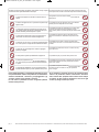
Ricordiamo che l'utilizzo di prodotti che impiegano energia elettrica ed acqua, comporta
l'osservanza di alcune regole fondamentali di sicurezza quali:
We remind you that the use of products that employ electrical energy and
water requires that a number of essential safety rules be followed, including:
È vietato l'uso dell'apparecchio ai bambini e alle persone inabili non
assistite.
This appliance must not be used be children and unaided dis-
abled persons.
È vietato toccare l'apparecchio se si è a piedi nudi e con parti del corpo
bagnate o umide.
It is prohibited to touch the appliance when you are barefoot
and with parts of the body that are wet or damp.
È vietata qualsiasi operazione di manutenzione o di pulizia, prima di
aver scollegato l'apparecchio dalla rete di alimentazione elettrica posi-
zionando l'interruttore generale dell'impianto su "spento".
It is prohibited to perform any maintenance or cleaning opera-
tion before having disconnected the appliance from the
mains electricity network, by positioning the plant master switch
at "off"
È vietato modificare i dispositivi di sicurezza o di regolazione senza
l'autorizzazione e le indicazioni del costruttore dell'apparecchio.
It is prohibited to modify the safety or adjustment devices
without the manufacturer’s authorisation and precise instruc-
tions
È vietato tirare, staccare, torcere i cavi elettrici fuoriuscenti dall'apparec-
chio, anche se questo è scollegato dalla rete di alimentazione elettrica.
It is prohibited to pull, detach or twist the electrical cables
coming from the unit even if it is disconnected from the electri-
cal mains
È vietato salire con i piedi sull'apparecchio, sedersi e/o appoggiarvi
qualsiasi tipo di oggetto.
It is prohibited to climb onto the unit, sit on it and/or rest any
type of object on it.
È vietato spruzzare o gettare acqua direttamente sull'apparecchio.
It is prohibited to spray or jet water directly onto the unit.
È vietato aprire gli sportelli di accesso alle parti interne dell'apparec-
chio, senza aver prima posizionato l'interruttore generale dell'impianto
su "spento" .
It is prohibited to open the doors for accessing the internal parts
of the appliance without first having switched off the master
switch of the "system".
È vietato disperdere, abbandonare o lasciare alla portata di bambini il
materiale dell'imballo in quanto può essere potenziale fonte di pericolo.
It is prohibited to disperse, abandon or leave the packing mate-
rials within the reach of children, as they are a potential
source of danger
DC MAN I 05 000 CHP 10_0121_SIC 05/01/2021 14.53 Pagina 4

Manuale di Installazione e Manutenzione unità combinata di recupero calore con sistema termodinamico - combined heat recovery unit with reversible heat pump system, use and maintenance manual
pag. 5
DICHIARAZIONE CE DI CONFORMITÀ
EC DECLARATION OF CONFORMITY
IL FABBRICANTE
THE MANUFACTURER
Advantix SpA
Azienda /
Company
Via S.Giuseppe Lavoratore 24 37040
VR
Indirizzo /
Address
Cap /
Zip code
Provincia /
Province
Arcole
Italy /
Italy
Città /
City
Stato /
State
DICHIARA SOTTO LA PROPRIA ESCLUSIVA RESPONSABILITÀ
CHE LE MACCHINE
DECLARES UNDER ITS OWN RESPONSIBILITY THAT THE
MACHINERY
Unità di recupero calore con circuito frigorifero integrato
Heat recovery unit with air to air heat pump
OTA-RHP; OTAE-RHP; OTA-HPEI
Descrizione /
Description
Serie /
Series
Mod. 35; 60; 100; 150; 230; 320; 450
Modelli /
Models
Ventilazione forzata a doppio flusso con circuito frigorifero reversibile
in sequenza a recuperatore di calore statico
Double flow mechanical ventilation with air to air heat pump system
in addition to static heat recovery device
Funzione
Function
Unità combinata di recupero calore con sistema termodinamico
Combined heat recovery unit with reversible heat pump system
Denominazione commerciale
Commercial name
SONO CONFORMI ALLE SEGUENTI DIRETTIVE:
Direttiva 2006/42/CE del Parlamento Europeo e del Consiglio del 17 maggio 2006
relativa alle macchine;
Direttiva 2014/68/UE del Parlamento Europeo e del Consiglio del 15 maggio 2014
sulle attrezzature in pressione immesse nel mercato (PED), secondo il MODULO
A di YDOXWD]LRQHGHOODFRQIRUPLWjFRPHSUHYLVWRGDOO¶DOOHJDWR,,,;
Direttiva 2014/30/UE del Parlamento Europeo e del Consiglio del 26 febbraio
2014 concernente il riavvicinamento delle legislazioni degli Stati membri relative
alla compatibilità elettromagnetica;
Direttiva 2014/35/UE del Parlamento Europeo e del Consiglio del 26 febbraio
2014 concernente il riavvicinamento delle legislazioni degli Stati membri relative al
materiale elettrico destinato ad essere adoperato entro taluni limiti di tensione;
Direttiva 2011/65/UE del Parlamento Europeo e del Consiglio del 8 giugno 2011,
sulla restrizione dell'uso di sostanze pericolose nelle apparecchiature elettriche ed
elettroniche (RoHS 2);
Direttiva 2012/19/UE del Parlamento Europeo e del Consiglio del 4 luglio 2012 sui
rifiuti di apparecchiature elettriche ed elettroniche (RAEE);
CHE
al momento dell'immissione sul mercato, gli idrofluorocarburi contenuti in tali
DSSDUHFFKLDWXUH SURGRWWH QHOO¶8QLRQH VRQR FRQVLGHUDWL QHO VLVWHPD GL TXRWH
dell'Unione di cui al Capo IV del regolamento (UE) n. 517/2014 in quanto immessi
sul mercato da un produttore o importatore di idrofluorocarburi cui si applica
l'articolo 15 del regolamento (UE) n. 517/2014.
E AUTORIZZA
ARE IN COMPLIANCE WITH THE FOLLOWING DIRECTIVES:
Directive 2006/42/EC of the European Parliament and of the Council of
17 May 2006 on machinery;
Directive 2014/68/EU of the European Parliament and of the Council of
15 May 2014 on the market of pressure equipment (PED), MODULE A of
the conformity assessment procedures, in accordance with annex III;
Directive 2014/30/EU of the European Parliament and of the Council of
26 February 2014 on the approximation of the laws of the Member States
relating to electromagnetic compatibility;
Directive 2014/35/EU of the European Parliament and of the Council of
26 February 2014 on the harmonisation of the laws of Member States
relating to electrical equipment designed for use within certain voltage
limits;
Directive 2011/65/EU of the European Parliament and of the Council of 8
June 2011 on the restriction of the use of hazardous substances in
electrical and electronic equipment (RoHS 2);
Directive 2012/19/EU of the European Parliament and of the Council of 4
July 2012 on waste electrical and electronic equipment (WEEE);
THAT
when placing on the market, the hydrofluorocarbons contained in that
equipment , manufactured in the Union, are accounted for within the quota
system referred to in Chapter IV of Regulation (EU) No 517/2014 were placed
on the market by a producer or importer of hydrofluorocarbons subject to
Article 15 of Regulation (EU) No 517/2014.
AND AUTHORIZES
Paolo Ferroli
Nominativo /
Name
Via S.Giuseppe Lavoratore 24 37040
VR
Indirizzo /
Address
Cap /
Zip Code
Provincia /
Province
Arcole
Italia /
Italy
Città /
City
Stato /
State
A COSTITUIRE IL FASCICOLO TECNICO PER SUO CONTO
La presente perde ogni validità in caso di uso improprio o di eventuali
modifiche, da noi non autorizzate, apportate alle suddette macchine. È
fatto divieto di mettere in servizio le unità oggetto di questa
GLFKLDUD]LRQH SULPD FKH OD PDFFKLQD R O¶LPSLDQWR LQ FXL VDUDQQR
incorporate o assiemate siano conformi alle disposizioni della Direttiva
Macchine 2006/42/CE.
TO COMPILE THE TECHNICAL FILE
In case of improper use or unauthorized modification of the
machinery equipment, this document will loose its validity. It is
forbidden to put the unit that is object of this declaration in service
before the machine or the plant in which the machine will operate is
in compliance with the dispositions of Machinery Directive
2006/42/EEC and following modifications
Arcole (VR)
/¶$00,1,675$725( UNICO
THE GENERAL MANAGER
P. FERROLI
MODELLO / MODEL
MATRICOLA / SERIAL NUMBER
DATA COLLAUDO / TESTING DATE
DC MAN I 05 000 CHP 10_0121_SIC 05/01/2021 14.53 Pagina 5

Manuale di Installazione e Manutenzione unità combinata di recupero calore con sistema termodinamico - combined heat recovery unit with reversible heat pump system, use and maintenance manual
pag. 6
85&)5+3$
&)5+3
0DGHLQ,WDO\
857
6,67(0,,17(*5$7,&21',=,21$0(172
02'(//2
02'(/
0$75,&2/$
6(5,$/180%(5
7(16,21()$6,)5(48(1=$
92/7$*(3+$6(6)5(48(1&<
&255(17(0$66,0$$6625%,7$
0$;,1387&855(17
&2',&(
&2'(
'$7$',352'8=,21(
0$18)$&785,1*'$7(
$
857
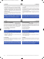
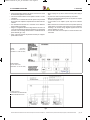
Le unità sono dotate di una targhetta di identificazione che riporta:
A - Marchio del Costruttore;
B - Indirizzo del Costruttore;
C - Modello unità;
D - Codice unità;
E - Matricola unità;
F - Data di produzione;
G - Tensione; n° fasi; frequenza di alimentazione;
H - Corrente assorbita massima;
I - Tipo refrigerante;
L - GWP refrigerante;
M - Carica refrigerante in kg e in tCO2eq;
N - Marcatura “CE”;
O - Categoria PED
The units feature a rating plate that describes the following:
A - Mark of the manufacturer;
B - Address of the manufacturer;
C - Unit model;
D - Unit code;
E - Unit serial number;
F - Manufacturinga date;
G - Voltage, number of phases; frequency of the power supply;
H - Max absorbed current;
I - Refrigerant type;
L - Refrigerant GWP;
M - Refrigerant charge in kg and tCO2eq;
N - “CE” mark;
O - PED Category
5()5,*(5$17(
5()5,*(5$17
&$5,&$
),//,1*
*:3
&2HT
&$7(*25,$8(3('
&$7(*$&25',1*728(3('
35(66,21,0$;',(6(5&,=,25()5,*(5$17(
0$;:25.,1*35(6685(65()5,*(5$176,'(
$/7$35(66,21(EDU
+,*+35(6685(EDU
%$66$35(66,21(EDU
/2:35(6685(EDU
7(030$;$3&
+30$;7(03&
7(030,1%3&
/30,17(03&
$SSDUHFFKLDWXUDHUPHWLFDPHQWHVLJLOODWD
&RQWDLQVIOXRULQDWHGJUHHQKRXVHJDVHV
FKHFRQWLHQHJDVIOXRUXUDWLDGHIIHWWRVHUUD
LQKHUPHWLFDOO\VHDOHGHTXLSPHQW
&
DC MAN I 05 000 CHP 10_0121_SIC 05/01/2021 14.53 Pagina 6
6HGHOHJDOHHGRSHUDWLYD
9LDOHGHOO,QGXVWULD4, 0ARCOLE95
7HO045.7636585
HPDLOLQIR#advantixspait
ZZZmaxaFRP

Manuale di Installazione e Manutenzione unità combinata di recupero calore con sistema termodinamico - combined heat recovery unit with reversible heat pump system, use and maintenance manual
pag. 7
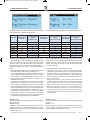
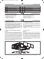
Le unità di rinnovo dell’aria OTARHPOTAE-RHP sono
caratterizzate dall’a-dozione di un doppio sistema di recupero
dell’energia, altrimenti persa nella fase di espulsione dell’aria viziata:
il primo, di tipo statico, mediante un recuperatore a flussi incrociati
con piastre in alluminio, il secondo (in cascata al precedente), di tipo
attivo, realizzato median-te circuito frigorifero reversibile.
Questo consente, con un unico apparato indipendente, di soddisfare
contemporaneamente al rinnovo dell’aria nel rispetto del comfort,
all’abbattimento dei carichi termici ad essa associati ed al risparmio
energetico, grazie all’elevatissima efficienza complessiva, sia inver-
nale che estiva.
Unitamente alle loro dimensioni compatte, le caratteristiche peculiari
di queste unità facilitano installazioni impensabili con sistemi tradizio-
nali, richiedendo essi maggiori complicazioni e costi impiantistici.
Queste unità si integrano in maniera ottimale ai tradizionali sistemi di
riscaldamento/condizionamento ambientale, siano essi dislocati in
serie od in parallelo.
La serie OTA-RHP è costituita da sette modelli, esclusivamente in
ver-sione orizzontale, per coprire un fabbisogno di ventilazione da
350 a 4500 m3/h.
Disponibile anche la serie OTAE-RHP con motori versione EC e
logica di controllo a portata costante.
I modelli delle serie OTA-RHP/OTAE-RHP possono essere
forniti in abbina-mento ad un sistema di ionizzazione dell’aria
denominato . Tale sistema, unico nel suo genere, ha
lo scopo di sanificare e deodorizzare l’aria e le superfici della
macchina, delle canalizzazio-ni e degli ambienti confinati.
The OTARHPOTAE-RHP heat recovery units are distinguished by
twin heat recovery system for transferring the energy
otherwise lost when extracting air from the room: the first system,
static type, by aluminium plated crossflow heat recovery, the
second system (in sequence to the previous one) by electric driven
air-to-air heat pump device. Therefore, by a single independent
system and at the same time, it can match the needing of ventilation
while ensuring room comfort, the outside air thermal loads and the
energy saving, due to the very high unit efficiency, both on winter
and summer time.
Together with their compact dimensions, the characteristics of these
units make the plant installations easier, especially when they
are really difficult (and much more expensive) by using
common hea-ting/cooling systems.
These units can be perfectly integrated into traditional room
hea-ting/cooling systems, placed in sequence or in parallel.
OTA-RHP series is composed of seven sizes, horizontal version
only, to cover a needing of ventilation from 350 up to 4500 m3/h. Also
available the seriesOTAE-RHP with EC fans and CAV
(Costant air volume) logic control.
The models of the series OTA-RHP/OTAE-RHP can be given
with a ionization system of the air called . This system,
unique in his type, makes the air and surfsces of the machine, of
the ducts and of the bordering rooms healthy and good smelling.
Questo manuale riporta le informazioni e quanto ritenuto necessario
per il trasporto, l'installazione, l'uso e la manutenzione delle unità
di trattamento aria OTARHP e OTAE-RHP.
L'utente troverà quanto è normalmente utile conoscere per una cor-
retta installazione in sicurezza dei recuperatori di calore descritti.
La mancata osservanza di quanto descritto in questo manuale e un’i-
nadeguata installazione del recuperatore di calore possono essere
causa di annullamento della garanzia che la Ditta Costruttrice dà ai
propri recuperatori. La Ditta Costruttrice inoltre non risponde di even-
tuali danni diretti e/o indiretti dovuti ad errate installazioni o per danni
causati da unità installate da personale inesperto e non autorizzato.
Verificare, all'atto dell'acquisto, che la macchina sia integra e com-
pleta. Eventuali reclami dovranno essere presentati per iscritto entro
8 giorni dal ricevimento della merce.
This manual describes the rules for the transportation, the installa-
tion, the use and the maintenance of the heat recovery. The user will
find everything that is normally useful to know for a correct and
safe installation of OTARHP and OTAE-RHP air treatment units.
The non-observance of what is described in this handbook and
an inadequate installation of the unit may cause the cancellation
of the guarantee that the Manufacturing Company grants on the
same one. The Manufacturing Company, moreover, does not answer
to possible direct and/or indirect damages due to wrong installation
carried out by inexpert and/or non-authorised staff. At the moment of
the purchase, check that the machine is integral and complete.
Claims will have to be produced within 8 days from the reception of
the goods.
DC MAN I 05 000 CHP 10_0121_SIC 05/01/2021 14.54 Pagina 7

Manuale di Installazione e Manutenzione unità combinata di recupero calore con sistema termodinamico - combined heat recovery unit with reversible heat pump system, use and maintenance manual
pag. 8
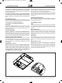
• Telaio in profilo di alluminio estruso, lega Anticorodal 63, con
giun-zioni di nodo in nylon precaricato.
• Pannelli di tamponamento di tipo sandwich sp. 23 mm, in
lamiera zincata internamente e preverniciata esternamente (RAL
9002) con isolamento termoacustico in poliuretano iniettato
con densità 45 kg/m3.
• Sezioni di filtrazione in corrispondenza delle prese aspiranti,
costi-tuite da filtri a celle sintetiche in classe di efficienza
ISO 16890 COARSE 55% (G4 EN779), estraibili sia
inferiormente che lateral-mente.
• Elettroventilatori centrifughi a doppia aspirazione a pale avanti
con motore elettrico direttamente accoppiato.
Su OTAE-RHP motore elettrico EC direttamente accoppiato e
driver dedicato; funzionamento standard a portata costante (escluse
taglie 35 e 60).
• Primo stadio di trasferimento termico (statico) mediante scambiato-
re del tipo aria-aria a flussi incrociati con piastre di scambio in
allu-minio; vasca inferiore di raccolta del condensato, estesa a
tutta la zona dedicata al trattamento termico.
• Secondo stadio di trasferimento termico (attivo) mediante circuito fri-
gorifero a pompa di calore (con gas R410A) costituito da
compres-sore ermetico (rotativo o scroll a seconda della
grandezza di mac-china), batterie evaporanti e condensanti a
geometria 25x22 con tubi in rame ed alettatura continua in
alluminio, valvola di espansio-ne elettronica, separatore e
ricevitore di liquido, valvola a 4 vie per inversione ciclo,
pressostati di alta e bassa pressione, filtro freon, spia del
liquido.
• Quadro elettrico interno per la gestione dei carichi; sonde di tempe-
ratura di tipo NTC su entrambi i circuiti aria; controllo elettronico
a microprocessore per lgestione automatica della
temperatura ambiente, della commutazione caldo/freddo e dei
cicli di sbrina-mento; pannello di comando remotabile fino a 20
m dall’unità, già implementatodi protocollo Modbus RTU per la
comunicazione con sistema di supervisione.
OTARHPOTAE-RHP
• Frame made from extruded Anticorodal 63 aluminium alloy
bars, connected by 3-way reinforced nylon joints.
• Sandwich panels, 23 mm thickness, galvanized sheet metal
inner skin and precoated (RAL 9002) sheet metal outer skin;
45 kg/m3 density foamed polyurethane as heat and sound
insulation.
• Filtering sections at both air intakes complete with efficiency cell
fil-ters ISO 16890 COARSE 55% (G4 EN779), extractable from
both lower and side removable panels.
• Direct driven double inlet forward curved centrifugal fans.
On OTAE-RHP EC motor centrifugal fans with dedicated driver;
con-stant air flow rate as standard operation (except size 35 and
60).
• First step of energy recovery (static type) by air-to-air crossflow alu-
minium heat exchanger; lower drain tray, estende to the whole area
of heat treatment.
• Second step of energy recovery (dynamic type) by air-to-air heat
pump system (R410A for all sizes) composed of electric driven com-
pressor (rotating or scroll type depending on unit size), evaporating
and condensating reversible Cu/Al finned coils, electronic expansion
valve, liquid receiver and separator, 4-way reversible valve, high
and low pressure switches, biflow freon filter, liquid indicator.
• Built-in electric box to control power loads, NTC temperature sen-
sors on both air circuits, electronic controller to control room tempe-
rature, heating/cooling mode and defrost cycles; remote control
panel (up to 20 m far from the unit), already prearranged with
Modbus RTU protocol for Building Management System.
• OTARHPOTAE-RHP
DC MAN I 05 000 CHP 10_0121_SIC 05/01/2021 14.54 Pagina 8

Manuale di Installazione e Manutenzione unità combinata di recupero calore con sistema termodinamico - combined heat recovery unit with reversible heat pump system, use and maintenance manual
pag. 9
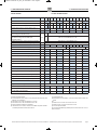
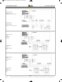
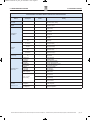
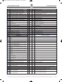
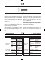
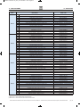
(1) Riferite alla portata nominale
(2) Livello di pressione sonora valutata a 1 m da: presa premente canalizzata / presa
aspirante / vano compressore.
(3) Aria esterna -5°C 80% UR; aria ambiente 20°C 50% UR
(4) Aria esterna 32°C 50% UR; aria ambiente 26°C 50% UR
(5) Esclusa la potenza assorbita per la ventilazione
(6) Limite inferiore con accessorio camera di miscela RMS, alla portata nominale e
con massima percentuale di aria di rinnovo del 40%
(1) At nominal airflow rate
(2) Sound pressure level calculated at 1 m far from: ducted air outlet / air intake / com-
pressor
box.
(3) Outside air at -5° 80% RH; room air at 20°C 50% RH
(4) Outside air at 32° 50% RH; room air at 26°C 50% RH
(5) Fan motor input not included
(6) Lower limits with RMS mixing chamber option, at nominal airflow rate, at 40% of
fresh air maximum.
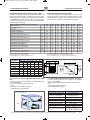
Portata aria nominale / Nominal air flow rate m³/h 350 600 1000 1500 2300 3200 4500
Pressione statica utile / E.S.P.(1) Pa 165 270 170 285 195 295 155 290 155 365 185 265 175 270
Pressione statica utile / E.S.P.(1) Pa 140 245 100 215 140 240 95 230 95 305 115 195 110 205
Livello di pressione sonora / Sound pressure level (2) dB (A) 59 / 47 / 51 64 / 50 / 55 62 / 49 / 55 67 / 54 / 57 65 / 51 / 60 68 / 54 / 59 70 / 56 / 60
Condizioni limite invernali versione standard /
Winter working limits standard version
°C / %
RMin -10° C OUT & Min 19°C 50% IN
Condizioni limite invernali con accessorio RMS e/o BER-
PRR / Winter working limits with RMS option
and/or BER-PRR (6)
RMin -20° C OUT & Min 19°C 50% IN
Condizioni limite estive / Summer working limits standard TMAX 38°C 50% OUT & MAX 27°C IN
Campo variazione portata / Airflow change range %±10%
Alimentazione elettrica / Electrical supply V/ph/H 230 / 1 / 50-60 400 / 3+N / 50
Corrente assorbita massima / Full load amperage A5.3 9.0 13.2 20.2 10.0 15.4 16.8
Efficienza recupero statico / Static recovery efficiency %62 51 50 50 50 50 50
Potenza termica totale / Total heating capacity kW 3.4 5.7 9.8 14.3 20.8 29.6 35.6
Potenza termica recupero attivo / Heat pump capacity kW 1.7 3.0 5.1 7.4 10.1 15.3 16.6
COP globale / Unit COP(5) W/W 10.3 8.9 9.4 9.6 12.6 10.6 13.8
Temperatura di immissione / Supply air temperature °C 23.5 23.2 24.1 23.0 21.5 23.0 19.0
Efficienza recupero statico / Static recovery efficiency %54 50 50 50 50 50 49
Potenza frigorifera totale / Total cooling capacity kW 2.2 3.6 6.3 9.0 13.4 19.4 21.9
Potenza frigorifera recupero attivo / Cooling capacity kW 1.8 3.0 5.3 7.5 11.0 16.2 17.7
EER globale / Unit EER(5) W/W 4.7 4.3 4.5 4.3 5.6 4.7 5.9
Temperatura di immissione / Supply air temperature °C 18.5 19.6 19.6 19.9 19.6 19.5 21.2
Refrigerante - GWP / Refrigerant - GWP R410A - 2088
Numero compressori - numero circuiti / 1 - 1 1 - 1 1 - 1 1 - 1 1 - 1 1 - 1 1 - 1
Carica refrigerante / Refrigerant filling kg 1.5 1.5 2.6 3.0 3.2 3.6 3.8
CO2 equivalente / CO2 equivalent Ton 3.1 3.1 5.4 6.2 6.6 7.5 7.9
DC MAN I 05 000 CHP 10_0121_SIC 05/01/2021 14.54 Pagina 9

Manuale di Installazione e Manutenzione unità combinata di recupero calore con sistema termodinamico - combined heat recovery unit with reversible heat pump system, use and maintenance manual
pag. 10
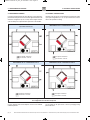
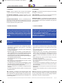
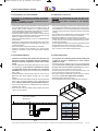
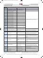
Le prese aspiranti posso essere disposte in linea a 90° mediante
scambio di pannelli.
The air intakes can be layed in-line or at 90° by changing closing
panels each other.
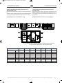
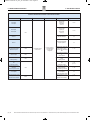
In relazione alla disposizione dei canali dell'aria, le prese aspiranti e
prementi dell'unità possono essere orientate opportunamente fino ad
ottenere le configurazioni (01, 02, 1S, 2S) come di seguito illustrato,
ciascuna delle quali va espressamente specificata in fase d'ordine.
According to air duct layout, unit air intakes and air outlets can match
up to 4 plant configurations (01, 02, 1S, 2S) as shown below, each of
which to be specified at ordering.
Aria espulsa / Exhaust air
Aria di rinnovo / Fresh air
Aria espulsa / Exhaust air
Aria di rinnovo / Fresh air
Aria espulsa / Exhaust air
Aria di rinnovo / Fresh air
Aria espulsa / Exhaust air
Aria di rinnovo / Fresh air
DC MAN I 05 000 CHP 10_0121_SIC 05/01/2021 14.54 Pagina 10

Manuale di Installazione e Manutenzione unità combinata di recupero calore con sistema termodinamico - combined heat recovery unit with reversible heat pump system, use and maintenance manual
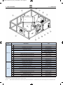
pag. 11
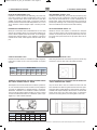
%
(
/
',
)
*
)
<
6FDULFR
'UDLQ
6FDULFR
'UDLQ
6FDULFR
'UDLQ
6FDULFR
'UDLQ
$
$
&
&
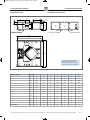
(1) presa aria esterna / outside air
(2) presa aria ambiente / return air
(3) immissione aria trattata / supply air
(4) espulsione aria viziata / exhaust air
OTARHP
mm
mm
mm
mm
mm
mm
mm
mm
mm
mm
mm
mm
mm
kg
1540 1540 1840 1840 2040 2040 2240
370 370 410 500 550 650 710
1240 1240 1440 1440 1690 1690 1890
1495 1495 1795 1795 1995 1995 2195
1294 1294 1494 1494 1744 1744 1944
300 300 400 400 500 500 600
210 210 210 310 410 510 510
232 232 233 233 299 332 332
458 458 703 470 571 500 604
115 115 264 264 264 291 291
85 85 85 85 85 85 85
80 80 80 75 70 70 80
90 90 55 118 120 180 180
122 125 185 228 267 281 329
DC MAN I 05 000 CHP 10_0121_SIC 05/01/2021 14.54 Pagina 11

Manuale di Installazione e Manutenzione unità combinata di recupero calore con sistema termodinamico - combined heat recovery unit with reversible heat pump system, use and maintenance manual
pag. 12
• Resistenza elettrica di pre-riscaldamento integrata -
• Resistenza elettrica di post-riscaldamento integrata -
• Tettuccio parapioggia -
• Cuffie presa aria diretta -
• Sezione con batteria ausiliaria ad acqua -
• Kit valvola a 2 vie con servomotore on/off -
• Kit valvola a 3 vie con servomotore on/off -
• Filtri ad alta efficienza -
• Pressostato differenziale -
• Attacco circolare -
• Serranda di regolazione con servocomando ON/OFF 230V -
• Serranda di regolazione con servocomando ON/OFF 230V
ritorno a molla -
• Silenziatore da canale -
• Terminale utente remoto -
• Sistema di sanificazione
• Scheda seriale Modbus -
• Sezione 3 serrande per miscela/ricircolo con servocomando -
• Internal electric pre-heating coil -
• Internal electric post-heating coil -
• Weather canopy -
• Fresh air/exhaust air casing -
• Additional water coil section -
• 2-way water valve kit with on/off actuator -
•3-way water valve kit with on/off actuator -
• High efficiency filters -
• Air filter pressure switch -
• Round air duct adaptor -
• Adjusting damper with damper actuator ON/OFF 230V -
• Adjusting damper with damper actuator ON/OFF 230V
spring return -
•Duct silencer -
•Wall mount remote control panel -
• Purifying system
• Modbus serial card -
• 3 dampers section for mixing/recirculating with actuator -
Potenza nominale / Nominal capacity kW 1,5 1,5 3 3 6 9 12
Tensione / Voltage V 230 230 230 230 400 400 400
Fasi / Phases n° 1 1 1 1 3 3 3
Stadi / Steps n° 1 1 1 1 1 1 1
Assorbimento / Current A 6,5 6,5 13 13 8,7 13 17,4
Peso / Weight kg 1,5 1,5 1,5 1,5 2,5 4 5
Copertura parapioggia della stessa finitura dei pannelli, sporgente 50
mm da ciascun lato dell’unità.
Viene fissato con viti che consentono lo smontaggio per la manuten-
zione ordinaria dai pannelli superiori, anziché inferiori, nel caso di
unità appoggiata a terra.
Weather pre-painted roof cover, protruding 50 mm from each unit
side.
It is fixed by screws suitable for a easy scheduled maintenance remo-
ving top panels, instead of bottom panels, in case of floor mounted
unit.
Completano il kit per l’installazione da esterno, per la presa dell’aria
di rinnovo e l’espulsione dell’aria esausta senza necessità di canaliz-
zazioni. Completa di rete antivolatile.
It complete the external kit, for fresh and exhaust air streams when
unit is installed outside. Provided with bird net.
Le resistenze, complete di termostati di sicurezza e di relè di coman-
do, sono del tipo a filamento per contenere le perdite di carico.
La resistenza è fortemente raccomandata per il funziona-
mento con temperature esterne inferiori a -10°C. E' installata in ripre-
sa aria ambiente ed effettua un pre-riscaldamento indiretto dell’aria
esterna nel flusso opposto di rinnovo. Così si evita efficaciemente la
formazione di brina nel flusso di espulsione, e si aumenta il rendi-
mento termico dello scambiatore quando si attiva la resistenza, recu-
perando buona parte del calore.
La resistenza di post-riscaldamento è installata interna-
mente alla macchina, immediatamente a monte del ventilatore di
mandata.
Le caratteristiche tecniche sono indicate nella tabella seguente.
The electric heater contains a filament-type element, which limits
pressure drop, and it is mounted inside the unit. Safety thermostats
and control relay are included.
The it is strongly recommended for functioning when out-
door temperatures are lower than -10°C. It is installed in ambient
return air stream and performs an idirect pre-heating of the outdoor air
in the opposite fresh air.
This effectively avoids frost formation on the exhaust flow of heat
recovery and it increases the thermal performance of the exhanger
when activating resistance, recovering much of the heat.
The post-heating coil is mounted immediately upstream
of the supply fan.
The technical characteristics are shown in the following table.
DC MAN I 05 000 CHP 10_0121_SIC 05/01/2021 14.54 Pagina 12

Manuale di Installazione e Manutenzione unità combinata di recupero calore con sistema termodinamico - combined heat recovery unit with reversible heat pump system, use and maintenance manual
pag. 13
Il kit (V2O o V3O) consente la regolazione on-off della batteria ausi-
liaria ad acqua SBFR.
Il kit viene fornito smontato ed è composto da:
- valvola
- servomotore on-off (alimentazione 230 V)
- raccorderia idraulica preassemblata
The V2O or V3O kit allows the on-off regulation of the additional
water coil section SBFR
The kit is supplied dismounted and includes the following items:
- valve
- on-off actuator (230V power supply)
- preassembled hydraulic fittings
Kit V2O / V2O kit
Pressione nominale / Nominal pressure PN16 (ISO7268/EN1333)
Attacchi Ø1 / Ø1 connections Filettati gas maschio 3/4”-1”
Threaded male GAS 3/4”-1”
KVs 4,0 m3/h - 10 m3/h
Corsa regolazione / Control stroke 2,5 mm - 6,5 mm
Azione attuatore / Actuator type On - off
Tempo di corsa / Running time 3,5 min - 2,5 min
Alimentazione / Power supply 230 V / 50/60 Hz
Grado di protezione / Protection class IP40
Condizioni di lavoro / Working conditions
Temperatura / Temperature: 0 ÷ 50°C ;
U.R. / R.H. : 10 ÷ 90 %
(senza condensa / without condensing)
Ø1
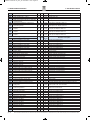
(1) Aria in ingresso 20°C; acqua in/out 70/60°C
(2) Aria in ingresso 20°C; acqua in/out 45/40°C
(3) Aria in ingresso 21°C - 75% UR; acqua in/out 7/12°C
(1) Air inlet temperature 20°C; in/out water temperature 70/60°C
(2) Air inlet temperature 20°C; in/out water temperature 45/40°C
(3) Air inlet temperature 21°C - 75% RH; in/out water temperature 7/12°C
Trova spazio in apposito modulo in lamiera zincata coibentata, colle-
gabile all’unità attraverso idonea canalizzazione; essa può essere
impiegata per aiutare la pompa di calore nella modalità riscaldamen-
to o raffreddamento. Tramite kit valvola V2O o V3O, dotata di servo-
comando on/off alimentato a 230V, essa può venire pilotata diretta-
mente dall’elettronica di bordo.
It takes place inside an external insulated section, connected to the
unit through air ducts; it can be used as additional heating or cooling
system. By V2O or V3O water valve kit, provided with on/off 230 V
actuator, it can be controlled by unit electronic control directly.
430 500 700 700 700 700
290 410 500 600 600 700
395 450 480 660 710 710
250 260 310 410 410 510
230 210 330 410 410 510
3/4” 3/4" 3/4" 3/4" 3/4" 1"
22 22 22 22 22 22
14 17 24 29 34 42
C
E
==
D
==
A
B
Ø1
Ø1
Ø2
SUPPLY
AIR
ARIA DI
RINNOVO
ARIA DI
RINNOVO
SUPPLY
AIR
Geometria / Geometry 2522 2522 2522 2522 2522 2522 2522
Tubi per rango / Pipes per row n° 13 13 16 25 26 26 32
Ranghi / Rows n° 3 3 3 3 3 3 3
Passo alette / Fin spacing mm 2,1 2,1 2,1 2,1 2,1 2,1 2,1
Resa termica / Heating capacity (1) kW 4,2 6,3 9,8 15,7 23,9 30,9 42,5
Temperatura uscita aria / Off air temperature (1) °C 55,4 51,1 48 49,9 49,7 47,6 48,0
Resa termica / Heating capacity (2) kW 2,0 3,1 4,8 7,8 11,8 15,3 21,0
Temperatura uscita aria / Off air temperature (2) °C 37,5 35,6 33,7 34,8 34,6 33,7 33,9
Portata acqua / Water flow rate m3/h 0,4 0,6 0,9 1,4 2,1 2,7 3,7
Perdita carico lato acqua / Water pressure drop kPa 10 11 5 18 23 23 15
Perdita carico lato aria / Air pressure drop Pa 13 32 43 34 37 54 59
Potenza frigorifera / Total cooling capacity kW 1,3 2 2,2 5,5 8,6 10,4 13,1
Temperatura uscita aria / Off air temperature °C 15,0 15,4 17,3 15 14,9 15,6 16,1
Portata acqua / Water flow rate m3/h 0,2 0,3 0,4 0,9 1,5 1,8 2,2
Perdita carico lato acqua / Water pressure drop kPa 5 6 2 12 16 14 10
Perdita carico lato aria / Air pressure drop Pa 19 45 60 46 51 75 85
DC MAN I 05 000 CHP 10_0121_SIC 05/01/2021 14.54 Pagina 13

Manuale di Installazione e Manutenzione unità combinata di recupero calore con sistema termodinamico - combined heat recovery unit with reversible heat pump system, use and maintenance manual
pag. 14
Disponibili in classe di efficienza ISO 16890 ePM170% (F7 EN 779),
sono di tipo compatto con media in polipropilene e telaio in acciaio
zincato e possono essere inseriti a bordo macchina al posto dello
standard, su entrambe le sezioni filtranti. La particolare costruzione
permette di limitare l’incremento medio della perdita di carico a circa
10 Pa, riducendo i consumi energetici rispetto a soluzioni più tradi-
zionali.
Available as ISO 16890 ePM170% (F7 EN 779) class efficiency, they
are compact type with polypropylene media and galvanized steel
frame; they can install inside the unit in place of standard filter, on
both air intakes. Thanks to the particular construction, the average air
pressure drop increasing 10 Pa, so that energy consumption is much
lower than traditional filter solutions with the same efficiency.
Realizzati in lamiera zincata, essi consentono un rapido collegamen-
to dell’unità a condotti circolari, sia nel lato premente che in quello
aspirante.
Made from galvanized steel sheet metal, they let an as fast as easy
connection to round air ducts, both on air intakes and outlets.
Sono dispositivi che servono ad intercettare o calibrare la portata d’a-
ria; sono costituite da telaio ed alette in lamiera zincata, predisposte
con perno per abbinamento a comando manuale o servomotore.
Quest’ultimo, in abbinata con la serranda ne consente la motorizza-
zione; sono del tipo ON-OFF oppure ON-OFF con ritorno a molla di
sicurezza ed alimentazione 230V. Per le dimensioni (riferite al pas-
saggio aria), si veda la tabella sottostante.
They are devices able to shut off or balance the airflow rate; their
frame and blades are made from galvanized steel sheet metal, prear-
ranged with shaft for handle adjuster or electric actuator. The latter, it
is suitable to be coupled to damper; ON-OFF control, or ON-OFF with
security spring return type, 230V power supply. For dimensions
(referred to air crossing section), the following table is to be used.
Idoneo per il controllo dello stato di intasamento dei filtri, esso viene
applicato ad un pannello laterale vicino alla sezione filtrante da con-
trollare e cablato al quadro elettrico di macchina. In caso di raggiun-
gimento della massima perdita di carico impostata, il pannello di
comando avvisa l’utente, tramite apposito codice di allarme sul dis-
play.
Suitable to control air filter condition, it is mounted on a side panel
close to the filtering section to be controlled and wired to unit electri-
cal board. In case of dirty filter (as max air pressure drop to be set),
the remote control panel informs the user by specific alarm code on
the display.
210 210 310 410 510 510
300 400 400 500 500 600
200 315 315 355 400 450
100 100 100 100 100 100
DC MAN I 05 000 CHP 10_0121_SIC 05/01/2021 14.54 Pagina 14

Manuale di Installazione e Manutenzione unità combinata di recupero calore con sistema termodinamico - combined heat recovery unit with reversible heat pump system, use and maintenance manual
pag. 15
The OTA-RHP air handling units are properly designed and
manufac-tured to almost completely eliminate phenomena of air
leaks through the structures and consequently the annoying
squealing sound. The noise is due to the moving components and
propagates in any direc-tion. To win the noise component towards
external unit structure, the panels are properly soundproof, while the
noise to the air ducts (spe-cially after fan outlets) can be won by
special SILENCERS. These silencers, with a rectangular cross-
section, are made from a galvani-sed steel plate frame filled with
glass wool and lined by a compact fabric called “velovetro”, which
prevents the flaking of the wool fibre and consequently the
entrainment of the fibres in the ducts, all enclo-sed by micro-
perforated metal plate on both sides. The sound wave generated
by the fan is damped by the impact with the walls of the silencing
media, with pressure drop limited to 40 Pa at nominal air-flow.
%
+
/
300 300 600 600 600 750
300 450 450 600 750 750
900 900 900 900 900 900
22 30 48 64 80 100
i silenziatori possono essere installati indifferentemente con i setti in posizione orizzontale o verticale
the silencers can be mounted with splitters either in horizontal or vertical position
Le unità di trattamento aria OTA-RHP sono progettate e costruite
a regola d’arte con criteri che annullano quasi completamente i
feno-meni di trafilamento dell’aria attraverso le strutture e i
conseguenti fastidiosi sibili ad essi connessi. Il rumore è generato
dagli organi in movimento e tende a propagarsi in qualsiasi
direzione. Per la com-ponente verso la struttura esterna, le pareti
sono adeguatamente insonorizzate, mentre quella verso le
canalizzazioni (in special modo, quelle prementi) può essere
contrastata da appositi SILENZIATORI a setti. I setti, a sezione
rettangolare, sono costituiti da un telaio in lamiera di acciaio
zincata riempito con lana di vetro rivestita da un tessuto compatto,
detto “velovetro”, che impedisce lo sfaldamento delle fibre della
lana e il loro conseguente trascinamento nei canali, e racchiusa da
lamiera microstirata sui due lati. L’onda sonora genera-ta dal
ventilatore viene smorzata dall’urto con le pareti dei setti, con
perdite di carico contenute attorno a 40 Pa alla portata nominale.
4716 29 50 50 45
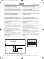
L’accessorio TUP consente di collegare un terminale utente aggiunti-
vo remotabile fino ad una distanza massima di 50 m, mediante cavo
telefonico a 6 vie (non fornito, a cura dell’installatore). Tutte le infor-
mazioni e le funzionalità del terminale a bordo macchina sono repli-
cate nel terminale remoto.
Il terminale remoto è idoneo al fissaggio a
parete: tutte le istruzioni per il collegamen-
to e il fissaggio sono fornite a corredo con
l’accessorio.
Per il collegamento all’interno della
macchina seguire lo schema di seguito
riportato. Se specificato in fase d’ordine, la
scheda di collegamento aggiuntiva è già
predisposta all’interno del quadro, a corre-
do è fornito solo il cavo telefonico per col-
legare la scheda principale alla schedina di connessione dei terminali.
TUP option is a remote panel for maximum 50m distance from the
unit, by 6 ways telephone cable (not supplied by the manufacturer,
but by the installer). All the informations and the features of the main
display on board are repeated on the remote display.
The remote display is suitable for wall
installation: all the informations for wiring
and fixing are supplied with the remote dis-
play.
For the main board wiring see the picture
below. Additional board with connector is
installed in the unit, if specified in the
order, one additional telephone cable to
connect board to controller is supplied.
DC MAN I 05 000 CHP 10_0121_SIC 05/01/2021 14.54 Pagina 15

Manuale di Installazione e Manutenzione unità combinata di recupero calore con sistema termodinamico - combined heat recovery unit with reversible heat pump system, use and maintenance manual
pag. 16
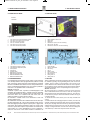
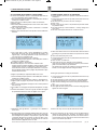
La tecnologia del sistema è costituita da uno speciale
condensatore formato da un cilindro realizzato in quarzo e da speciali
maglie metalliche e viene alimentato con una tensione alternata
monofase, a basso consumo energetico.
The technology is constituted by a special condenser
made by a cylinder of quartz and by special metallic net and it is fee-
ded by a monophase alternate tension, low power consumption.
Esso consente la riduzione della carica batterica all’interno del canale
mediante ionizzazione del flusso d’aria che attraversa la batteria di
condensatori al quarzo e la sanificazione dell’aria introdotta negli
ambienti, innalzandone il livello di qualità, risulta attivo solo a venti-
lazione attiva.
It allows the reduction of bacterial activity inside air ducts by ioniza-
tion of the airflow crossing the quartz capacitor rows and the sanita-
tion of the air supplied to the room, increasing the indoor air quality, it
works when fans are running.
Alimentazione elettrica / Electrical supply V/ph/Hz 230/1/50
Potenza assorbita / Power input W 4,5 9 18 18 20
Assorbimento / Current mA 20 39 78 78 87
Max tratto sanificabile / Max sanitized lenght m 25 25 25 25 25
L mm 350 350 350 350 350
W mm 400 500 600 600 700
H mm 370 410 550 650 710
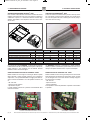
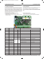
Modulo inseribile nell’ unità logica di controllo già cablata al quadro
elettrico di bordo, il quale consente l’interfaccia con un sistema di
supervisione, a cui è possibile demandare la maggior parte delle fun-
zioni di controllo normalmente a carico del pannello di controllo, ad
es:
- ON / OFF unità
- Controllo velocità ventilatori
- impostazione set point
E’ inoltre possibile visionare tutti i parametri di funzionamento della
macchina in funzione.
Module insertable into the control logic already wired to the electrical
board, which allows the interface with a supervision system, to which
you can delegate most of the control functions normally charged to
the control panel, for example :
- ON / OFF unit
- Speed control fans
- Set point adjustment
It 'also possible to view all the parameters of operation of the machine
in operation.
Scheda Modbus / PCB Modbus
Connettore scheda Modbus / PCB Modbus connector
DC MAN I 05 000 CHP 10_0121_SIC 05/01/2021 14.54 Pagina 16

Manuale di Installazione e Manutenzione unità combinata di recupero calore con sistema termodinamico - combined heat recovery unit with reversible heat pump system, use and maintenance manual
pag. 17
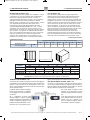
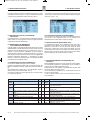
120 A
L
D135 D
100 E
H
B
C
SCARICO O22
DRAIN O22
SCARICO
O
22
DRAIN
O
22
mm 500 500 600 600 700 700 800
mm 420 420 420 420 470 470 470
mm 1240 1240 1440 1440 1690 1690 1890
mm 300 300 400 400 500 500 600
mm 210 210 210 310 410 510 510
mm 370 370 410 500 550 650 710
mm 620 620 720 720 820 820 920
kg 30 30 40 45 62 70 90
SEZIONE FORNITA SEPARATAMEMENTE E DA INSTALLARE IN CANTIERE /
SECTION SUPPLIED SEPARATELY AND TO BE INSTALLAED
Sistema di miscelazione dell’aria esterna con aria di espulsione attivo
in
modalità invernale, completo di serrande e servocomandi modulanti,
che evita gli sbrinamenti ed estende il campo di lavoro fino a -20 °C
Heating mode mixing chamber with damper and modulating servo
actuators: external air is mixed expulsion air after heat recovery, in
order to reduce defrost cycle and the heat pump working up to -20 °C
air temperature.
DC MAN I 05 000 CHP 10_0121_SIC 05/01/2021 14.54 Pagina 17

Manuale di Installazione e Manutenzione unità combinata di recupero calore con sistema termodinamico - combined heat recovery unit with reversible heat pump system, use and maintenance manual
pag. 18
• Le unità trattamento aria e i loro accessori sono fornite imballate su
pallets e devono rimanere integre fino al momento del montaggio.
• I componenti che, per esigenze tecniche, costruttive, di trasporto o
qualsivoglia, non vengono montati a bordo macchina, ma spediti
separatamente all’interno dell’unità o meno, vengono protetti con
adeguati involucri e debitamente menzionati sulla bolla di accompa-
gnamento delle merci.
• Si diffida dal sovrapporre qualsiasi altro materiale sulla merce: la
ditta costruttrice declina ogni responsabilità in caso di danni derivanti
da tale carico.
• The air handling units are packed on pallets that must remain intact
until assembly.
• The components that, due to technical, constructional, transport or
other requirements are not fitted on the unit, but sent separately
either inside the unit or otherwise, are specially protected and duly
described on the packing list.
• No other material must be stacked on the products: the manufactu-
rer declines all liability in the event of damage deriving from such
loads.
Si consiglia che al ricevimento della merce, , sia
effettuato un controllo su tutto il materiale in consegna al fine di verifi-
care l’esistenza di eventuali danni causati dal trasporto. Gli eventuali
danni devono essere debitamente comunicati al vettore e specificati
nella clausola di riserva riportata nella bolla di accompagnamento.
E’ vivamente consigliato :
When receiving the goods, , all the material delive-
red must be checked to ascertain the presence of any damage caused
during transport. Any damage found must be reported to the carrier,
accepting the goods with reservation and specifying the type of dama-
ge on the delivery documents.
It is strongly recommended :
• Il peso di ogni singola macchina è riportato sul presente manuale.
• Evitare rotazioni senza controllo.
• Appoggiare con prudenza la merce in modo da evitarne bruschi
spostamenti o, peggio, cadute.
• The weight of the units is shown on this manual.
• Avoid uncontrolled rotations.
• Place the goods down with care, avoiding sudden movements or,
worse, dropping the goods.
In caso di stoccaggio prolungato prima dell’installazione, le macchine
dovranno essere protette dalla polvere, dalle intemperie e tenute lon-
tane da fonti di calore e vibrazioni.
In the event of extended storage before installation, keep the units pro-
tected from dust and bad weather and away from sources of vibrations
and heat.
DC MAN I 05 000 CHP 10_0121_SIC 05/01/2021 14.54 Pagina 18

Manuale di Installazione e Manutenzione unità combinata di recupero calore con sistema termodinamico - combined heat recovery unit with reversible heat pump system, use and maintenance manual
pag. 19
- L'utente è la persona, l'ente o la società, che ha acquistato
o affittato la macchina e che intende usarla per gli scopi concepiti.
- L'utilizzatore o operatore, è la per-
sona fisica che è stata autorizzata dall'utente a operare con la mac-
china.
- Come tali, si intendono quelle per-
sone fisiche che hanno conseguito uno studio specifico e che sono
quindi in grado di riconoscere i pericoli derivati dall'utilizzo di questa
macchina e possono essere in grado di evitarli.
- The customer is the person, the agency or the company
who bought or rented the unit
- The operator or user is the physical person who
uses the unit for the purpose for which it was designed
- It is composed by the physical trained per-
sons, able to recognize any danger due to the proper and improper use
of the unit and able to avoid or repair it inflammable or toxic gases at a
high temperature.
• Nelle operazioni di installazione, usare un abbigliamento idoneo e
antinfortunistico, ad esempio: occhiali, guanti, ecc. come indicato
dalle normative vigenti.
• Durante l'installazione operare in assoluta sicurezza, ambiente puli-
to e libero da impedimenti.
• Rispettare le leggi in vigore nel Paese in cui viene installata la mac-
china, relativamente all'uso e allo smaltimento dell'imballo e dei pro-
dotti impiegati per la pulizia e la manutenzione della macchina, non-
ché osservare quanto raccomanda il produttore di tali prodotti.
• Prima di mettere in funzione l'unità controllare la perfetta integrità dei
vari componenti e dell'intero impianto.
• Evitare assolutamente di toccare le parti in movimento o di interpor-
si tra le stesse.
• Non procedere con i lavori di manutenzione e di pulizia, se prima
non è stata disinserita la linea elettrica.
• La manutenzione e la sostituzione delle parti danneggiate o usurate
deve essere effettuata solamente da personale specializzato ese-
guendo le indicazioni riportate in questo manuale.
• Le parti di ricambio devono corrispondere alle esigenze definite dal
Costruttore.
• In caso di smantellamento dell’unità, attenersi alle normative antin-
quinamento previste.
L'installatore e l'utilizzatore nell'uso dell’unità devono tenere
conto e porre rimedio a tutti gli altri tipi di rischio connessi con l'im-
pianto. Ad esempio rischi derivanti da ingresso di corpi estranei, oppu-
re rischi dovuti al convogliamento di gas pericolosi infiammabili o tos-
sici ad alta temperatura.
• Wear suitable and accident-prevention clothing during installation,
for example: goggles, gloves etc. as indicated in the current regula-
tion
• During installation operate in complete safety, clean environment
and free from obstructions.
• Respect the laws in force, in the country in which the machine is
installed, relative to use and disposal of packaging and the products
used for cleaning and maintenance of the machine, as well as
complying with that recommended by the producer of these pro-
ducts.
• Before starting the unit, check the perfect integrity of the various
components of the entire plant.
• Do not touch moving parts or intervene between these.
• Do not perform maintenance and cleaning until the electric line has
been connected.
• The maintenance and replacement of damaged or worn parts must
only be performed by specialised staff and following the indications
given in this manual.
• The spare parts must correspond to the requirements defined by the
Manufacturer.
• If the unit must be dismantled, follow the envisioned anti-pollution
standards.
When using the unit, the installer and user must consider and
solve all risks connected to theplant. For example, risks deriving from
the entry of foreign bodies or risks due to the conveying of dangerous
inflammable or toxic gases at a high temperature.
DC MAN I 05 000 CHP 10_0121_SIC 05/01/2021 14.54 Pagina 19

Manuale di Installazione e Manutenzione unità combinata di recupero calore con sistema termodinamico - combined heat recovery unit with reversible heat pump system, use and maintenance manual
pag. 20
• Operare rispettando le norme di sicurezza in vigore, accertandosi
della sufficiente libertà di movimento e della pulizia degli ambienti di
installazione.
• Usare idoneo abbigliamento antinfortunistico e dispositivi individua-
li di protezione (occhiali, guanti, ecc.).
• Trasportare la sezione imballata il più possibile vicino al luogo di
installazione.
• Non sovrapporre attrezzi o pesi sull'unità imballata.
• Non usare l'unità come deposito per attrezzi di cantiere.
• Evitare di toccare le parti mobili e di usare le stesse come punti di
sollevamento/movimentazione.
• Verificare la perfetta integrità dei vari componenti dell'unità.
•
Verificare che il piano di appoggio o di sostegno sia in grado di soppor-
tare il peso della(e) macchina(e) e tale da non causare vibrazioni.
• Verificare che il piano di appoggio o di sostegno sia perfettamente
orizzontale onde permettere il corretto accoppiamento delle varie
sezioni.
• Non posizionare l’unità in locali in cui siano presenti gas infiamma-
bili, sostanze acide, aggressive e corrosive che possono danneg-
giare i vari componenti in maniera irreparabile.
• Prevedere spazi tecnici adeguati tali da garantire le operazioni di
installazione nonché di manutenzione e di sostituzione dei compo-
nenti quali batterie, filtri ecc.
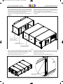
• Nell’eventualità che la macchina debba essere installata sospesa
bisogna prevedere un sistema di aggancio a soffitto per ciascuna
delle sezioni che compongono l’unità di trattamento.
•
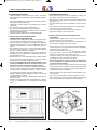
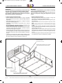
• Posizionare l'unità su di una struttura solida adeguata al peso della
macchina; interporre sempre opportuni sistemi flessibili e smorzan-
ti tra unità e struttura di supporto (si veda fig. 1). Evitare le connes-
sioni rigide, fonte di trasmissione meccanica delle vibrazioni.
• Regolare l’altezza dei punti di appoggio in modo che la macchina
risulti perfettamente orizzontale.
• Posizionare l'unità in modo che il deflusso della condensa possa
avvenire facilmente.
• Prevedere uno spazio laterale libero ed accessibile pari a 500 mm
min (fig. 2), compatibilmente con la configurazione di installazione
scelta.
• Work while meeting the current safety regulations, ensuring suffi-
cient space to move and the cleanliness of jobsite.
• Wear protective clothing and personal protective equipment (glas-
ses, gloves, etc.).
• Move the packed section as close as possible to the place of instal-
lation.
• Don't place tools or other jobsite equipment over the packed unit.
• Don't use the unit as a store of yard tools.
• Don't touch moving parts and don't use them as supports.
• Check the full integrity of all unit components.
• Make sure that the support surface is able to support the weight of
the unit(units) and will not cause vibrations.
• Make sure that the support surface is perfectly horizontal so as to
Allow the correct coupling of the various sections.
• Never position the unit in rooms where there are flammable gases
or acidic, aggressive or corrosive substances that may irreparably
damage the various components.
• Leave a minimum amount of free space around the unit, as shown
in the figure, so as to allow for installation, maintenance and the
replacement of components, such as coils, filters etc.
• If the unit is hung from the ceiling all the sections that make up the
air handling unit must be connected to the ceiling
•
• Place the unit over a solid support structure, suited to unit weight;
always interpose proper anti-vibration devices between the unit and
the supports (see fig. 1). Avoid rigid connections, they are source of
mechanical transmission of vibrations
• Adjust the height of the support points so that the machine is per-
fectly horizontal.
• Place the unit so that the water condensate outflow can be easy
• Leave a gap space of min 500 mm (see fig. 2) between the unit side
and the closest obstacles, according to the unit configuration.
DC MAN I 05 000 CHP 10_0121_SIC 05/01/2021 14.54 Pagina 20
La pagina si sta caricando...
La pagina si sta caricando...
La pagina si sta caricando...
La pagina si sta caricando...
La pagina si sta caricando...
La pagina si sta caricando...
La pagina si sta caricando...
La pagina si sta caricando...
La pagina si sta caricando...
La pagina si sta caricando...
La pagina si sta caricando...
La pagina si sta caricando...
La pagina si sta caricando...
La pagina si sta caricando...
La pagina si sta caricando...
La pagina si sta caricando...
La pagina si sta caricando...
La pagina si sta caricando...
La pagina si sta caricando...
La pagina si sta caricando...
La pagina si sta caricando...
La pagina si sta caricando...
La pagina si sta caricando...
La pagina si sta caricando...
-
 1
1
-
 2
2
-
 3
3
-
 4
4
-
 5
5
-
 6
6
-
 7
7
-
 8
8
-
 9
9
-
 10
10
-
 11
11
-
 12
12
-
 13
13
-
 14
14
-
 15
15
-
 16
16
-
 17
17
-
 18
18
-
 19
19
-
 20
20
-
 21
21
-
 22
22
-
 23
23
-
 24
24
-
 25
25
-
 26
26
-
 27
27
-
 28
28
-
 29
29
-
 30
30
-
 31
31
-
 32
32
-
 33
33
-
 34
34
-
 35
35
-
 36
36
-
 37
37
-
 38
38
-
 39
39
-
 40
40
-
 41
41
-
 42
42
-
 43
43
-
 44
44


MAXA OTA-RHP 35÷450 Manuale del proprietario
- Categoria
- Condizionatori d'aria a sistema split
- Tipo
- Manuale del proprietario
in altre lingue
- English: MAXA OTA-RHP 35÷450 Owner's manual
Documenti correlati
Altri documenti
-
Bartscher 110677 Istruzioni per l'uso
-
Tecnosystemi AIR DYN SYSTEM heat recovery Manuale del proprietario
-
Haier HACI-RPE 200 Installation, Use And Maintenance Manual
-
Moog Videolarm FusionDome FDP75C12N Installation And Operation Instructions Manual
-
Moog Videolarm FDW75 Manuale utente
-
Moog Videolarm RHW75C12N Manuale utente
-
Redmond RMC-PM4506E Manuale del proprietario