Moog QView QFDPT4-70NA Installation And Operation Instructions Manual
- Categoria
- Telecamere di sicurezza
- Tipo
- Installation And Operation Instructions Manual
Questo manuale è adatto anche per

Moog Inc.
Sensor and Surveillance Systems
3650 Woodhead Drive Northbrook, IL. USA 60062
+1.847.498.0700 Fax: +1.847.498.1258 www.moogS3.com
Installation and Operation Instructions
Before attempting to connect or operate this product, please
read these instructions completely.
© 2013, Moog Inc. All Rights Reserved 81-IN5247 111113
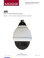
QFD
QView™ FusionDome Multiple Camera System
QFDPT2-70NA........... Standard 7” outdoor, pendant mount, tinted dome, with (2) day / night cameras, 3-9mm auto-iris lens
QFDPT4-70NA........... Standard 7” outdoor, pendant mount, tinted dome, with (4) day / night cameras, 3-9mm auto-iris lens

IMPORTANT SAFEGUARDS SAFETY PRECAUTIONS
UNPACKING
SERVICE
1 Read these instructions.
2 Keep these instructions.
3 Heed all warnings
4 Follow all instructions.
5 Do not use this apparatus near water.
6 Clean only with damp cloth.
7 Do not block any of the ventilation openings. Install in accordance with the
manufacturers instructions.
8 Cable Runs- All cable runs must be within permissible distance.
9 Mounting - This unit must be properly and securely mounted to a supporting
structure capable of sustaining the weight of the unit.
Accordingly:
a. This installation should be made by a qualied service person and should conform
to all local codes.
b. Care should be exercised to select suitable hardware to install the unit, taking into
account both the composition of the mounting surface and the weight of the unit.
10 Do not install near any heat sources such as radiators, heat registers, stoves, or other
apparatus ( including ampliers) that produce heat.
11 Do not defeat the safety purpose of the polarized or grounding-type plug. A
polarized plug has two blades with one wider than the other. A grounding type
plug has two blades and a third grounding prong. The wide blade or the third
prong are provided for your safety. When the provided plug does not t into your
outlet, consult an electrician for replacement of the obsolete outlet.
12 Protect the power cord from being walked on or pinched particularly at plugs,
convenience receptacles, and the point where they exit from the apparatus.
13 Only use attachment/ accessories specied by the manufacturer.
14 Use only with a cart, stand, tripod, bracket, or table specied by the manufacturer,
or sold with the apparatus. When a cart is used, use caution when moving the cart/
apparatus combination to avoid injury from tip-over.
15 Unplug this apparatus during lighting storms or when unused for long periods of time.
16 Refer all servicing to qualied service personnel. Servicing is required when the
apparatus has been damaged in any way, such as power-supply cord or plug is
damaged, liquid has been spilled of objects have fallen into the apparatus, the
apparatus has been exposed to rain or moisture, does not operate normally, or
has been dropped.
Be sure to periodically examine the unit and the supporting structure to make sure that the integrity
of the installation is intact. Failure to comply with the foregoing could result in the unit separating
from the support structure and falling, with resultant damages or injury to anyone or anything struck
by the falling unit.
Unpack carefully. Electronic components can be
damaged if improperly handled or dropped. If an item
appears to have been damaged in shipment, replace
it properly in its carton and notify the shipper.
Be sure to save:
1 The shipping carton and packaging material.
They are the safest material in which to make future
shipments of the equipment.
2 These Installation and Operating Instructions.
If technical support or service is needed, contact us at
the following number:
The lightning ash with an arrowhead symbol,
within an equilateral triangle, is intended to
alert the user to the presence of non-insulated
“dangerous voltage” within the product’s
enclosure that may be of sufcient magnitude
to constitute a risk to persons.
Este símbolo se piensa para alertar al usuario a la presencia
del “voltaje peligroso no-aisIado” dentro del recinto de los
productos que puede ser un riesgo de choque eléctrico.
Ce symbole est prévu pour alerter I’utilisateur à la presence
“de la tension dangereuse” non-isolée dans la clôture de
produits qui peut être un risque de choc électrique.
Dieses Symbol soll den Benutzer zum Vorhandensein der
nicht-lsolier “Gefährdungsspannung” innerhalb der
Produkteinschließung alarmieren die eine Gefahr des
elektrischen Schlages sein kann.
Este símbolo é pretendido alertar o usuário à presença “di
tensão perigosa non-isolada” dentro do cerco dos produtos
que pode ser um risco de choque elétrico.
Questo simbolo è inteso per avvertire I’utente alla presenza
“di tensione pericolosa” non-isolata all’interno della
recinzione dei prodotti che può essere un rischio di scossa
elettrica
.
The exclamation point within an equilateral
triangle is intended to alert the user to
presence of important operating and
maintenance (servicing) instructions in the
literature accompanying the appliance.
Este símbolo del punto del exclamation se piensa para
alertar al usuario a la presencia de instrucciones importantes
en la literatura que acompaña la aplicación.
Ce symbole de point d’exclamation est prévu pour alerter
l’utilisateur à la presence des instructions importantes dans
la littérature accompagnant l’appareil.
Dieses Ausruf Punktsymbol soll den Benutzer zum
Vorhandensein de wichtigen Anweisungen in der Literatur
alarmieren, die das Gerät begleitet.
Este símbolo do ponto do exclamation é pretendido alertar o
usuário à presença de instruções importantes na literatura
que acompanha o dispositivo.
Questo simbolo del punto del exclamaton è inteso per
avvertire l’utente alla presenza delle istruzioni importanti nella
letteratura che accompagna l'apparecchio.
TECHNICAL SUPPORT
AVAILABLE 24 HOURS
1- 800-554 -1124
RISK OF ELECTRIC SHOCK
DO NOT OPEN
CAUTION
CAUTION: TO REDUCE THE RISK OF
ELECTRIC SHOCK, DO NOT REMOVE
COVER ( OR BACK). NO USER- SERVICE-
ABLE PARTS INSIDE. REFER SEVICING
TO QUALIFIED SERVICE PERSONNEL.
MADEIN
BUY AMERICA COMPLIANT • COUNTRY OF ORIGIN U.S.A.
USA

Product Warranty Registration
Register Your Products Online
www.moogS3.com/technical-support/product-registration
Moog values your patronage. We are solely committed to providing you with the highest quality products and
superior customer service. With 3-Year and 5-Year warranties (depending on the product purchased) we stand
behind every product we sell.
:
• Simple and Trouble-Free RMA process
• Product / software updates
• Special promotions
• Eliminate the need to archive purchase documents such as receipts, purchase orders, etc.
See full warranty details at www.moogS3.com/technical-support/warranty-plan/

Limited Warranty for Moog Products
Moog - Decatur Operations, subsequently referred to as “Manufacturer,” warrants these products to be free from defects in material or workmanship as follows:
During the labor warranty period, to repair the Product, Purchaser will either return the defective product, freight prepaid, or deliver it to Manufacturer at Moog Decatur
Operations, 2525 Park Central Boulevard, Decatur, Georgia, 30035. The Product to be repaired is to be returned in either its original carton or a similar package affording
an equal degree of protection with a RMA # (Return Materials Authorization number) displayed on the outer box or packing slip. To obtain a RMA# you must contact our
Technical Support Team at 800.554.1124, extension 101. Manufacturer will return the repaired product freight prepaid to Purchaser. Manufacturer is not obligated to
provide Purchaser with a substitute unit during the warranty period or at any time. After the applicable warranty period, Purchaser must pay all labor and/or parts charges.
The limited warranty stated in these product instructions is subject to all of the following terms and conditions.
TERMS AND CONDITIONS
1. NOTIFICATION OF CLAIMS: WARRANTY SERVICE: If Purchaser believes that the Product is defective in material or workmanship, then written notice with an explanation
of the claim shall be given promptly by Purchaser to Manufacturer. All claims for warranty service must be made within the warranty period. If after investigation,
Manufacturer determines the reported problem was not covered by the warranty, Purchaser shall pay Manufacturer for the cost of investigating the problem at its then
prevailing per incident billable rate. No repair or replacement of any Product or part thereof shall extend the warranty period of the entire Product. The specic warranty on
the repaired part only shall be in effect for a period of ninety (90) days following the repair or replacement of that part or the remaining period of the Product parts warranty,
whichever is greater.
2. EXCLUSIVE REMEDY: ACCEPTANCE: Purchaser’s exclusive remedy and Manufacturer’s sole obligation is to supply (or pay for) all labor necessary to repair any Product
found to be defective within the warranty period and to supply, at no extra charge, new or rebuilt replacements for defective parts.
3. EXCEPTIONS TO LIMITED WARRANTY: Manufacturer shall have no liability or obligation to Purchaser with respect to any Product requiring service during the warranty
period which is subjected to any of the following: abuse, improper use, negligence, accident, or acts of God (i.e., hurricanes, earthquakes), modication, failure of the
end-user to follow the directions outlined in the product instructions, failure of the end-user to follow the maintenance procedures recommended by the International Security
Industry Organization, written in product instructions, or recommended in the service manual for the Product. Furthermore, Manufacturer shall have no liability where a
schedule is specied for regular replacement or maintenance or cleaning of certain parts (based on usage) and the end-user has failed to follow such schedule; attempted
repair by non-qualied personnel; operation of the Product outside of the published environmental and electrical parameters, or if such Product’s original identication
(trademark, serial number) markings have been defaced, altered, or removed. Manufacturer excludes from warranty coverage Products sold AS IS and/or WITH ALL FAULTS
and excludes used Products which have not been sold by Manufacturer to the Purchaser. All software and accompanying documentation furnished with, or as part of the
Product is furnished “AS IS” (i.e., without any warranty of any kind), except where expressly provided otherwise in any documentation or license agreement furnished with
the Product. ANY COST ASSOCIATED WITH REMOVAL OF DEFECTIVE PRODUCT AND INSTALLATION OF REPLACEMENT PRODUCT IS NOT INCLUDED IN THIS WARRANTY.
4. PROOF OF PURCHASE: The Purchaser’s dated bill of sale must be retained as evidence of the date of purchase and to establish warranty eligibility.
PRODUCT CATEGORY PARTS \ LABOR
All Enclosures and Electronics Five (5) Years
Accessory Brackets Five (5) Years
Controllers Three (3) Years
Power Supplies / IR Illuminators Three (3) Years
Poles / PolEvators™ / CamEvator Three (3) Years
Warrior Series™ / Q-View™Three (3) Years
SView Series™Three (3) Years 6 months if used in auto scan / tour operation
DeputyDome™, NiteTrac™, Igloo Dome, PurgeDome™Three (3) Years 6 months if used in auto scan / tour operation
EXO Series™ Dome and Fixed Camera Systems* Three (3) Years 6 months if used in auto scan / tour operation
EXO Series™ GeminEye Visible and Thermal Camera Systems One (1) Year
DISCLAIMER OF WARRANTY
EXCEPT FOR THE FOREGOING WARRANTIES, MANUFACTURER HEREBY DISCLAIMS AND EXCLUDES ALL OTHER WARRANTIES, EXPRESS OR IMPLIED, INCLUDING, BUT
NOT LIMITED TO ANY AND/OR ALL IMPLIED WARRANTIES OF MERCHANTABILITY, FITNESS FOR A PARTICULAR PURPOSE AND/OR ANY WARRANTY WITH REGARD TO ANY
CLAIM OF INFRINGEMENT THAT MAY BE PROVIDED IN SECTION 2-312(3) OF THE UNIFORM COMMERCIAL CODE AND/OR IN ANY OTHER COMPARABLE STATE STATUTE.
MANUFACTURER HEREBY DISCLAIMS ANY REPRESENTATIONS OR WARRANTY THAT THE PRODUCT IS COMPATIBLE WITH ANY COMBINATION OF NON-MANUFACTURER
PRODUCTS OR NON-MANUFACTURER RECOMMENDED PRODUCTS PURCHASER MAY CHOOSE TO CONNECT TO THE PRODUCT.
LIMITATION OF LIABILITY
THE LIABILITY OF Manufacturer, IF ANY, AND PURCHASER’S SOLE AND EXCLUSIVE REMEDY FOR DAMAGES FOR ANY CLAIM OF ANY KIND WHATSOEVER, REGARDLESS
OF THE LEGAL THEORY AND WHETHER ARISING IN TORT OR CONTRACT, SHALL NOT BE GREATER THAN THE ACTUAL PURCHASE PRICE OF THE PRODUCT WITH RESPECT
TO WHICH SUCH CLAIM IS MADE. IN NO EVENT SHALL MANUFACTURER BE LIABLE TO PURCHASER FOR ANY SPECIAL, INDIRECT, INCIDENTAL, OR CONSEQUENTIAL
DAMAGES OF ANY KIND INCLUDING, BUT NOT LIMITED TO, COMPENSATION, REPLACEMENT LABOR COSTS, REIMBURSEMENT, OR DAMAGES ON ACCOUNT OF THE LOSS
OF PRESENT OR PROSPECTIVE PROFITS OR FOR ANY OTHER REASON WHATSOEVER.
* NOTE
Moog will repair or replace, at its option, any equipment which is damaged by transient voltage surge/spike or lightning strike (an “Occurrence”), while properly connected
to wired AC power line with protective ground. Any repair or modication of the equipment done by someone other than Moog voids the warranty.
Form 500-911 081913

!
!
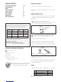
ELECTRICAL SPECIFICATIONS (OUTDOOR ONLY):
Power 24Vac, Class 2 Only
26 watts at 24Vac (accessories)
Heater: 25 watts
Blower: .84 watts
Input Connectors (outdoor units):
BNC Connectors - 1 for each camera
Screw-down connectors - 2
NOTE: This unit is designed for operation in an upright position. In
stalling the FusionDome™ upside down may cause damage
to the internal equipment, and will void the warranty.
CAMERAS VOLTAGE CURRENT POWER
1 24 Vac/Vdc 102mA 2.5W
2 24 Vac/Vdc 210mA 5W
3 24 Vac/Vdc 331mA 7.9W
4 24 Vac/Vdc 487mA 10.9W
Use the formula below to select the correct power supply for cameras connected
in parallel (positive to positive, negative to negative):
Total current for a 24 Vac system:
TOTAL CURRENT = (202mA x total number of cameras)
Note: 202mA is camera plus power supply
CABLE AND POWER GUIDELINES (Detailed info on Page 12)
This chart shows the proper current needed for power supplies for QView™
cameras. Use Class 2 Power only. Input voltage must be 24 Vac/Vdc.
GENERAL INSTRUCTIONS:
Tools Required: .100" Flat Head Screwdriver, Phillips Head Screwdriver
Carefully remove the housing from the packaging material. Check to be sure all parts
are present.
TABLE OF CONTENTS
Cable and Power Guidelines 4, 11
Pendant Mounting 4
Wiring 4
Camera Adjustment 5
Camera Focusing 5
Camera Settings 6, 7
NVT Instructions 8
Exploded View 10
Warranty Information 3
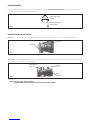
PENDANT MOUNTING THE QFD
1. This unit includes a 1½" NPT housing coupling that can be used with a standard
1½" NPT pipe or with brackets designed with 1½" male pipe threads, such as the
Moog WM20G.
2. Attach the coupling to the bracket or pendant pipe (Figure 1).
NOTE: Pipe threads should be clean and rust free. Use a sealer (such as Teon™
tape or silicone sealer) on the threads for outdoor applications.
Be sure the bracket is properly and securely mounted to a supporting
structure capable of rigidly holding the weight of the entire unit.
Figure 1
Add thread seal-
ing tape
Figure 2
Twist and
Secure
3. Bring all wiring through the NPT pipe or bracket.
4. Mount the housing assembly to the mounting bracket and housing coupling. A
safety cable is included with the housing to temporarily hold it while making wiring
connections. Loop the safety cable over one of the set screws on the housing coupling
(Figure 2).
5. Make the proper connections to the incoming power (See Wiring section below) and
attach all BNC connectors to the video in.
6. Place the nished wiring inside the pendant pipe. Undo the safety cable and twist
the housing onto the housing coupling. Secure all (3) setscrews provided on the
housing coupling (Figure 2 above).
WIRING
1. Attach the incoming power and accessory wiring using the color code chart below.
1 Camera Power (24 Vac) Red
2 Camera Power (24 Vac) Orange
3 Accessory Power (24 Vac) Yellow
4 Accessory Power (24 Vac) Green
NOTE: Polarity is not important in this unit.

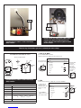
CAMERA ADJUSTMENT
1. Access the cameras by removing the dome. Loosen the locking screws on the lip of the dome. DO NOT TAKE THESE SCREWS OUT. Once the screws are loosened, turn the
dome counter clock-wise until it stops, then pull the dome off (Figure 3).
Loosen screws only, do
not remove
Figure 3
Remove dome by twisting
counterclockwise
CAMERA FOCUSING (FOR EACH CAMERA)
Fixed Lens: Loosen the set screw in the lens mount. Manually rotate the lens until a clear picture is achieved. Once the focus is set, retighten the set screw (Figure 4).
Figure 4
Set screw
Fixed lens
Auto Iris Lens:
NOTE: THE AUTO IRIS LENS IS SET AT THE FACTORY.
• IF YOU EXPERIENCE VIDEO TOO LIGHT OR DARK AUTO IRIS ADJUSTMENT MAY BE NEEDED.
Vari-Focal Lens: First, adjust the Magnication Lock Screw to the desired magnication (telephoto to wide angle). Tighten the Lock Screw. Next, adjust the Focus Lock Screw
until a clear picture is achieved. Tighten the Lock Screw (Figure 5).
Figure 5
Magnication lock
screw
Focus lock
screw
Fixed iris
vari-focal lens

Included with every camera is an On Screen Display
(OSD) controller.
Included with every camera is an On Screen Display
(OSD) controller.
In order to make any change to the camera setting
you must rst connect the OSD controller to the
camera. Note the camera must be powered in order
to access menus.
Controller
Use the Multi Tact Switch within the camera
Direction and Enter Guide
Camera
Connection
Follow the steps listed below to gain access and modify the camera settings
LT RT
UP
DN
OSD
CONTROLLER
LT RT
UP
DN
Left
Down
Right
Up Enter
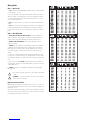
OSD MENU FUNCTION
LENS DC MANUAL
EXPOSURE SHUTTER BRIGHTNESS AGC DWDR
WHITE BAL ATW1 ATW2 AWC -> SET MANUAL
BACKLIGHT OFF BLC HLC
DAY & NIGHT AUTO COLOR B/W EXT
SPECIAL CAM TITLE MOTION PRIVacY IMAGE ADJ
DPC LANGUAGE VERSION
RESET FACTORY
EXIT
* START SET UP MENU
1) LENS
Press the Middle Multi Tact Switch,
the main setup menu is displayed on the monitor screen
Turn the Switch toward Left or Right side, Select DC or MANUAL
SETUP
LENS DC
EXPOSURE
WHITE BAL ATW1
BACKLIGHT OFF
DAY & NIGHT AUTO
SPECIAL
RESET
EXIT
SETUP
LENS DC
EXPOSURE
WHITE BAL ATW1
BACKLIGHT OFF
DAY & nIGHT AUTO
SPECIAL
RESET
EXIT
Select the function
by using the switch
* Simply make the
adjustment in the
following order to help
make the focusing
easier:
- Select MANUAL
- Adjust lens focus well
- Then return to DC
* A function with
the icon has
sub menus. To
select a sub
menu, select a
function with the
icon and press
the switch
Down
Up
Enter
Left Right
MANUAL

2) EXPOSURE
NTSC: 1/60, PAL: 1/50
FLK
1/250 - 1/100,000
*darker brighter
Attention BRIGHTNESS adjusts DC
level of the lens
255
ON - 000 - 063
SHUTTER
BRIGHTNESS
DWDR
SHUTTER AUTO
BRIGHTNESS 000
DWDR OFF
SETUP
LENS DC
EXPOSURE
WHITE BAL ATW1
BACKLIGHT OFF
DAY & NIGHT AUTO
SPECIAL
RESET
EXIT
255
013
008
005
3) WHITE BALANCE
BLUE 000
RED 000
255
255
ATW1 (wider range)
ATW2 (narrower range)
AWC -> SET
MANUAL
WB MANUAL
SETUP
LENS DC
EXPOSURE
WHITE BAL ATW1
BACKLIGHT OFF
DAY & NIGHT AUTO
SPECIAL
RESET
EXIT
INDOOR
OUTDOOR
MANUAL
255
255
009
AREA 2
NIGHT ONLY
010
011
010
OFF
4) BACKLIGHT
Attention When select BLC,
AREA 1 always turns on
BLC
HLC
SETUP
LENS DC
EXPOSURE
WHITE BAL ATW1
BACKLIGHT OFF
DAY & NIGHT AUTO
SPECIAL
RESET
EXIT
AREA SEL. AREA 1
AREA STATE ON
GRIN 000
HEIGHT 000
WIDTH 000
LEFT/RIGHT 000
TOP/BOTTOM 000
LEVEL 000
MODE ALL DAY
OFF
ON
LOW
5) DAY & NIGHT
WARNING Do not change
the above factory-set levels
*DDN *TDN
AUTO
BW
EXIT
COLOR
IR GRAIN 000
WIDTH 000
HEIGHT 000
LEFT/RIGHT 000
TOP/BOTTOM 000-009
D -> N LEVEL 040-224 140-224
D -> N DELAY 1 SEC - 60SEC
N -> D LEVEL 000-184 000084
N -> D DELAY 1 SEC - 60SEC
BURST ON
IR SMART OFF
IR LEVEL HIGH
SETUP
LENS DC
EXPOSURE
WHITE BAL ATW1
BACKLIGHT OFF
DAY & NIGHT AUTO
SPECIAL
RESET
EXIT
7) RESET & EXIT
FACTORY RESET
SETUP
LENS DC
EXPOSURE
WHITE BAL ATW1
BACKLIGHT OFF
DAY & NIGHT AUTO
SPECIAL
RESET
EXIT
ON
* DEAD PIXEL
COMPENSATION
ON
*UPDATE VERSION
OFF *CAMERA TITLE
6) SPECIAL
MOTION DETECTION
PRICACY MASKING
IMAGE ADJUST
SETUP
LENS DC
EXPOSURE
WHITE BAL ATW1
BACKLIGHT OFF
DAY & NIGHT AUTO
SPECIAL
RESET
EXIT
SPECIAL
CAM TITLE ON
MOTION OFF
PRIVacY OFF
IMAGE ADJ.
DPC
LANGUAGE ENGLISH
VERSION 10 10 21
RETURN RET
*SPECIAL SUB MENU LIST
(
(
SPECIAL
CAM TITLE ON
MOTION ON
PRIVacY OFF
IMAGE ADJ.
DPC
LANGUAGE ENGLISH
VERSION 10 10 21
RETURN RET
SPECIAL
CAM TITLE ON
MOTION OFF
PRIVacY ON
IMAGE ADJ.
DPC
LANGUAGE ENGLISH
VERSION 10 10 21
RETURN RET
SPECIAL
CAM TITLE ON
MOTION ON
PRIVacY OFF
IMAGE ADJ.
DPC
LANGUAGE ENGLISH
VERSION 10 10 21
RETURN RET
013
108
OFF
011
167
255
AREA 4
AREA 8
ON 000 - 255
FONT 000 - 255
LCD
RETURN
ID&TITLE 000 - 255
USER
013
180
011
092
031
255
015
OFF
OFF
OFF
OFF
OFF
AREA SEL. AREA 1
AREA STATE ON
HEIGHT 000
WIDTH 000
LEFT/RIGHT 000
TOP/BOTTOM 000
DEGREE 000
VIEW ON
AREA SEL. AREA 1
AREA STATE ON
HEIGHT 000
WIDTH 000
LEFT/RIGHT 000
TOP/BOTTOM 000
COLOR 000
LENS SHAD. OFF
2DNR ON
MIRROR ON
FONT COLOR
CONTRAST 000
SHARPNESS 000
DISPLAY CRT
NEG. IMAGE ON
Attention When select ON,
AREA 1 always turns on
* LENS SHAD: LENS SHADING COMPENSATION
* 2 DNR: SIGNAL NOISE REDUCTION (2D)
* NEG IMAGE: NEGATIVE IMAGE
* GAMMA
* PED LEVEL
* COLOR GAIN

NVT INSTRUCTIONS
The cameras included in the QView™ series have the option of transmitting video signals to NVT receivers via unshielded twisted pair cable. You must purchase the receiver
separately. Instructions for connecting the receiver end of the unshielded twisted pair cable will be included with the NVT receiver. Following are instructions for connecting the
unshielded twisted pair cables to the RJ45 (Cat. 5) cable running outside your housing.
UNSHIELDED TWISTED PAIR VIDEO WIRING
1. Video for all four cameras is contained in the one RJ45 (Cat. 5) cable. An RJ45 female coupling is provided so that all connections can be made with an RJ45 connector. The
following is the wiring diagram for the four twisted pair wires that are included with the Cat. 5 cable.
2. Connect the other end of the unshielded twisted pair cable to the NVT receiver.
CAUTION: The unshielded twisted pair video signal is polarity dependent. The positive video wire for each camera MUST be connected to the positive terminal on the NVT receiver,
and negative MUST be connected to negative.
3. When using unshielded twisted pair cable you DO NOT need the BNC connector. All four BNC connectors are provided inside the housing for testing purposes. Be sure that there
is no video connection other than the unshielded twisted pair cable.
NOTE: The customer must purchase the Video Transceiver from
NVT. Part numbers are:
• NV-212A (500 ft.)
* NV-213A or NV-213A-M (1000 ft.)
• NV-652R, NV-862R, or NV-1662R (3000 ft.)
PIN WIRE COLOR CAMERA NUMBER
1 White/Green Camera 1 +
2 Green Camera 1 -
3 White/Orange Camera 2 +
6 Orange Camera 2 -
5 White/Blue Camera 3 +
4 Blue Camera 3 -
7 White/Brown Camera 4 +
8 Brown Camera 4 -

!
!
3
Wiring Notes
Wire — What to DO
1. DO use point-to-point Unshielded Twisted Pair wire, gauge 24 or thicker, stranded
or solid, Category 2, 3, 4, or 5.
2. The video signal may co-exist in the same wire bundle as other video, telephone,
data, control signals, or low-voltage power. It is also OK to run NVT video signals in
or near electromagnetic fields (in accordance with National Electrical Code, local, or
other local safety requirements).
3. DO measure the wire distance. Use only transceivers that are designed for that
distance.
4. DO make sure the pair of wires carrying the video signal is sent as a twisted pair
(e.g. the blue-white/white-blue wires twisted together as a pair), not a “split-pair”
(e.g. blue-white conductor, part of one pair/orange-white conductor, part of another
pair).
Wire — What NOT to DO
1. DO NOT USE SHIELDED TWISTED PAIR WIRE. It will severely degrade the
distance performance. Short runs may be used with some signal degradation (for
example elevator traveler cables). Multi-pair wire with an overall shield is OK.
2. DO NOT USE UN-TWISTED WIRE. It will reduce the NVT product’s inherent
interference immunity.
3. DO NOT allow your installation to have “bridge-taps”, loading coils, talk-battery,
or MOV type protectors. Bridge-taps are where a twisted pair is connected to two
twisted pairs (such as an extension phone at home). Bridge-taps cause reflections
as the signal propagates, resulting in “ghosts” in the video image, and are to be
avoided.
4. If the phone company is providing the cable runs between buildings, make sure
it’s “dry copper” i.e. it should have none of the following: dial-tone, 48 volts, loading
coils, bridge-taps, switching, or long paths to the phone company’s central office and
back.
5. Due to near-end crosstalk, DO NOT send a transmit and a receive signal in the
same wire bundle. Exceptions: Less than 1,000 ft (300m), or Category 5 cable, up to
2,000 ft (600m) are OK.
6. DO NOT send “Up-the-Coax” Pan/Tilt/Zoom signals through active (amplified)
NVT transceivers.
Measure your wire distance
Note: All NVT quoted distance specifications include any coax in the run. It is
recommended that the wire distance be measured to ensure that the capability of the
NVT product is correct.
Wire resistance may be measured with an ohm-meter by shorting the two conductors
together at the far end, and measuring the loop-resistance out and back. Compare
your readings with the charts in the next column.
7. For safety, never put NVT signals in the same conduit as high-voltage
wiring.
8. WARNING — to reduce a risk of fire or electrical shock, do not expose
this product to rain or moisture.

28
27
26
25 24
23
22
21
20
19
18
17
33
31
32
30
29
16
15
7
13
12
11
10
9
8
7
6
5
4
3
2
17 1/4 x 20 FH SS Bolt 90-BTSR01 1
18 Housing Pendant Bracket 30-VL926 1
19 1/4 Split Lock Washer 92-WSSL01 1
20 1/4 Flat Washer 92-WSFL01 1
21 Housing Gasket 96-PSGK05 1
22 1/4 x 20 x 1/2" Set Screw 90-BTSS05 2
23 1/4 Flat Washer 92-WSFL01 4
24 1/4 Split Lock Washer 92-WSSL01 4
25 1/4 x 20 x .75" HH Bolts 90-BTHH27 4
26 1 1/2" Housing Coupling 30-VL917 1
27 Upper Housing Gasket 96-PSGK04 1
28 1/4 x 20 x .375" HH Bolts 90-BTHH39 2
n/s 1/4 Flat Washer 92-WSFL01 2
n/s 1/4 Split Lock Washer 92-WSSL01 2
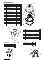
Item No. Description Part No. Qty
2 FD8 Housing Top 30-VL1697 1
3 Dome Support Ring 30-VL1695 1
4 25W, 24Vac w/Leads 72-HT1752 1
5 FD8 Clear Dome 20-DCFD8 1
n/s FD8 Tinted Dome 20-DTFD8 1
n/s 9.25" O-ring 96-RSORG11 2
6 Plastic Ring Plugs 30-VL1696 6
7 FD8 PCB 76-FPD8PB 1
8 FD8 Upper Housing Bracket 30-VL1744 1
9 Housing Gasket 96-PSGK05 3
10 Housing Fan 71-VLBL03 1
11 Adapter Bracket (In Housing Packet) 40-PKFD8 1
12 1/4 x 20 x .75" HH Bolts 90-BTHH27 4
12 1/4 Split Lock Washer 92-WSSL01 4
12 1/4 Flat Washer 92-WSFL01 4
13 10 x 32 x .75 Phil PH SS 90-BTRP28 3
15 Captive Screw 30-VL1749 3
n/s Captive Screw Spring 92-SPR01 3
n/s Captive Screw Retainer 94-FSRT04 3
16 Main Housing Bracket 30-VL1742 1
n/s Housing Ring 1" Lanyard Spring 92-SPR02 1
n/s Lanyard Spring Screws 90-BTPEM01 2
n/s Packet Assembly 40-PKFD8 1
n/s Power/Control/Video Input Cable 40-CAFD802 1
n/s Product Instructions 81-IN5215 1
Pendant Assembly
EXPLODED VIEWS OF HOUSING
29 FD8 Upper Housing Bracket 30-VL1013 1
30 Indoor Housing Coupling 30-VL1744 1
31 1/4 Flat Washer 92-WSFL01 1
32 1/4 Split Lock Washer 92-WSSL01 4
33 1/4 x 20 x .75" HH Bolts 90-BTHH27 4
Indoor Pendant Assembly
34
36
37
35
38
34 PC Board and Input Cables Video/Power RPQF01
35 Multi Camera Metal Base Bracket RPQF02
36 Plastic Articulated Bracket RPQRH71000
37 Camera Bracket and Hardware RPQRH71010
38 Hi-Res Lens RPQF8ONA
Camera Arm Assembly

Use the formula below to select the correct power supply for cameras connected in parallel (positive to positive, negative to negative):
Total current for a 24 Vac system:
TOTAL CURRENT = (202mA x total number of cameras) Example: 202mA x 5 total cameras = 1010mA
Note: 202mA is camera plus power supply
CAMERAS VOLTAGE CURRENT POWER
1 24 Vac/Vdc 102mA 2.5W
2 24 Vac/Vdc 210mA 5W
3 24 Vac/Vdc 331mA 7.9W
4 24 Vac/Vdc 487mA 10.9W
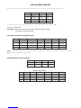
CABLE AND POWER GUIDELINES
This chart shows the proper current needed for power supplies for QView Series cameras. Use Class 2 Power only. Input voltage must be 24 Vac/Vdc.
Power Supply Cable Maximum Length (feet/meters)
CAMERAS TOTAL LOAD POWER SUPPLY 24 AWG 22 AWG 18 AWG 16 AWG
1 2.5W 24 Vac/Vdc 1718/523 2733/833 6909/2106 10985/3348
2 5W 24 Vac/Vdc 834/254 1327/404 3356/1023 5335/1626
3 7.9W 24 Vac/Vdc 529/161 842/256 2129/649 3385/1032
4 10.9W 24 Vac/Vdc 359/109 572/174 1447/441 2300/701
NOTE: The above table is based on a "worst-case" power supply. Using a regulated or switching power supply can increase your cable distance. Moog recommends using our
PS24 power supply, or a CSA/UL listed Class 2 power supply.
Video Cable Maximum Length (feet/meters)
Cable Type RG-59 RG-6 RG-11
Wire Gauge 23 AWG* 18 AWG* 16 AWG*
Max. Length 750/229 1500/457 2000/610
* Copper clad steel core, 95% braided shield
AWG 250/76 500/152 1000/305 1500/457 2000/610 3000/914
18 3Ω 6Ω 13Ω 19Ω 26Ω 40Ω
20 5Ω 10Ω 20Ω 30Ω 40Ω 59Ω
22 8Ω 17Ω 33Ω 48Ω 66Ω 99Ω
24 13Ω 26Ω 52Ω 78Ω 108Ω 163Ω
Maximum Length (feet/meters)
-
 1
1
-
 2
2
-
 3
3
-
 4
4
-
 5
5
-
 6
6
-
 7
7
-
 8
8
-
 9
9
-
 10
10
-
 11
11
-
 12
12


Moog QView QFDPT4-70NA Installation And Operation Instructions Manual
- Categoria
- Telecamere di sicurezza
- Tipo
- Installation And Operation Instructions Manual
- Questo manuale è adatto anche per
in altre lingue
- English: Moog QView QFDPT4-70NA
Documenti correlati
Altri documenti
-
Moog Videolarm QView QRHWT2-70NA Installation And Operation Instructions Manual
-
-
-
Spektrum 650TVL CCD FPV Camera NTSC Manuale utente
-
-
-
Samsung SCC-C6407 Manuale utente