Genius JA388 Istruzioni per l'uso
- Categoria
- Gate Opener
- Tipo
- Istruzioni per l'uso

JA388
CONTROL BOARD FOR 115V HINGED GATES
EQUIPO ELECTRÓNICO PARA PORTONES DE TIPO BATIENTE 115V
USE AND INSTALLATION INSTRUCTIONS
INSTRUCCIONES PARA EL USO – NORMAS DE INSTALACIÓN

AVVERTENZE PER L’INSTALLATORE
OBBLIGHI GENERALI PER LA SICUREZZA
1) ATTENZIONE! È importante per la sicurezza delle persone seguire attenta-
mente tutta l’istruzione. Una errata installazione o un errato uso del prodotto
può portare a gravi danni alle persone.
2) Leggere attentamente le istruzioni prima di iniziare l’installazione del prodot-
to.
3) I materiali dell’imballaggio (plastica, polistirolo, ecc.) non devono essere
lasciati alla portata dei bambini in quanto potenziali fonti di pericolo.
4) Conservare le istruzioni per riferimenti futuri.
5) Questo prodotto è stato progettato e costruito esclusivamente per l’utilizzo
indicato in questa documentazione. Qualsiasi altro utilizzo non espressamen-
te indicato potrebbe pregiudicare l’integrità del prodotto e/o rappresen-
tare fonte di pericolo.
6) GENIUS declina qualsiasi responsabilità derivata dall’uso improprio o diverso
da quello per cui l’automatismo è destinato.
7) Non installare l’apparecchio in atmosfera esplosiva: la presenza di gas o fumi
infiammabili costituisce un grave pericolo per la sicurezza.
8) Gli elementi costruttivi meccanici devono essere in accordo con quanto
stabilito dalle Norme EN 12604 e EN 12605.
Per i Paesi extra-CEE, oltre ai riferimenti normativi nazionali, per ottenere un
livello di sicurezza adeguato, devono essere seguite le Norme sopra riporta-
te.
9) GENIUS non è responsabile dell’inosservanza della Buona Tecnica nella co-
struzione delle chiusure da motorizzare, nonché delle deformazioni che
dovessero intervenire nell’utilizzo.
10) L’installazione deve essere effettuata nell’osservanza delle Norme EN 12453
e EN 12445. Il livello di sicurezza dell’automazione deve essere C+E.
11) Prima di effettuare qualsiasi intervento sull’impianto, togliere l’alimentazione
elettrica.
12) Prevedere sulla rete di alimentazione dell’automazione un interruttore
onnipolare con distanza d’apertura dei contatti uguale o superiore a 3 mm.
È consigliabile l’uso di un magnetotermico da 6A con interruzione onnipolare.
13) Verificare che a monte dell’impianto vi sia un interruttore differenziale con
soglia da 0,03 A.
14) Verificare che l’impianto di terra sia realizzato a regola d’arte e collegarvi
le parti metalliche della chiusura.
15) L’automazione dispone di una sicurezza intrinseca antischiacciamento co-
stituita da un controllo di coppia. E' comunque necessario verificarne la sogli
di intervento secondo quanto previsto dalle Norme indicate al punto 10.
16) I dispositivi di sicurezza (norma EN 12978) permettono di proteggere even-
tuali aree di pericolo da Rischi meccanici di movimento, come ad Es.
schiacciamento, convogliamento, cesoiamento.
17) Per ogni impianto è consigliato l’utilizzo di almeno una segnalazione lumino-
sa nonché di un cartello di segnalazione fissato adeguatamente sulla struttu-
ra dell’infisso, oltre ai dispositivi citati al punto “16”.
18) GENIUS declina ogni responsabilità ai fini della sicurezza e del buon funziona-
mento dell’automazione, in caso vengano utilizzati componenti dell’impian-
to non di produzione GENIUS.
19) Per la manutenzione utilizzare esclusivamente parti originali GENIUS.
20) Non eseguire alcuna modifica sui componenti facenti parte del sistema
d’automazione.
21) L’installatore deve fornire tutte le informazioni relative al funzionamento
manuale del sistema in caso di emergenza e consegnare all’Utente
utilizzatore dell’impianto il libretto d’avvertenze allegato al prodotto.
22) Non permettere ai bambini o persone di sostare nelle vicinanze del prodotto
durante il funzionamento.
23) Tenere fuori dalla portata dei bambini radiocomandi o qualsiasi altro datore
di impulso, per evitare che l’automazione possa essere azionata involonta-
riamente.
24) Il transito tra le ante deve avvenire solo a cancello completamente aperto.
25) L’Utente utilizzatore deve astenersi da qualsiasi tentativo di riparazione o
d’intervento diretto e rivolgersi solo a personale qualificato.
26) Tutto quello che non è previsto espressamente in queste istruzioni non è
permesso
IMPORTANT NOTICE FOR THE INSTALLER
GENERAL SAFETY REGULATIONS
1) ATTENTION! To ensure the safety of people, it is important that you read
all the following instructions. Incorrect installation or incorrect use of the
product could cause serious harm to people.
2) Carefully read the instructions before beginning to install the product.
3) Do not leave packing materials (plastic, polystyrene, etc.) within reach of
children as such materials are potential sources of danger.
4) Store these instructions for future reference.
5) This product was designed and built strictly for the use indicated in this
documentation. Any other use, not expressly indicated here, could compro-
mise the good condition/operation of the product and/or be a source of
danger.
6) GENIUS declines all liability caused by improper use or use other than that for
which the automated system was intended.
7) Do not install the equipment in an explosive atmosphere: the presence of
inflammable gas or fumes is a serious danger to safety.
8) The mechanical parts must conform to the provisions of Standards EN 12604
and EN 12605.
For non-EU countries, to obtain an adequate level of safety, the Standards
mentioned above must be observed, in addition to national legal regulations.
9) GENIUS is not responsible for failure to observe Good Technique in the
construction of the closing elements to be motorised, or for any deformation
that may occur during use.
10) The installation must conform to Standards EN 12453 and EN 12445. The safety
level of the automated system must be C+E.
11) Before attempting any job on the system, cut out electrical power.
12) The mains power supply of the automated system must be fitted with an all-
pole switch with contact opening distance of 3mm or greater. Use of a 6A
thermal breaker with all-pole circuit break is recommended.
13) Make sure that a differential switch with threshold of 0.03 A is fitted upstream
of the system.
14) Make sure that the earthing system is perfectly constructed, and connect
metal parts of the means of the closure to it.
15) The automated system is supplied with an intrinsic anti-crushing safety device
consisting of a torque control. Nevertheless, its tripping threshold must be
checked as specified in the Standards indicated at point 10.
16) The safety devices (EN 12978 standard) protect any danger areas against
mechanical movement Risks, such as crushing, dragging, and shearing.
17) Use of at least one indicator-light is recommended for every system, as well
as a warning sign adequately secured to the frame structure, in addition to
the devices mentioned at point “16”.
18) GENIUS declines all liability as concerns safety and efficient operation of the
automated system, if system components not produced by GENIUS are used.
19) For maintenance, strictly use original parts by GENIUS.
20) Do not in any way modify the components of the automated system.
21) The installer shall supply all information concerning manual operation of the
system in case of an emergency, and shall hand over to the user the warnings
handbook supplied with the product.
22) Do not allow children or adults to stay near the product while it is operating.
23) Keep remote controls or other pulse generators away from children, to
prevent the automated system from being activated involuntarily.
24) Transit through the leaves is allowed only when the gate is fully open.
25) The user must not attempt any kind of repair or direct action whatever and
contact qualified personnel only.
26) Anything not expressly specified in these instructions is not permitted.
CONSIGNES POUR L'INSTALLATEUR
RÈGLES DE SÉCURITÉ
1) ATTENTION! Il est important, pour la sécurité des personnes, de suivre à la
lettre toutes les instructions. Une installation erronée ou un usage erroné
du produit peut entraîner de graves conséquences pour les personnes.
2) Lire attentivement les instructions avant d'installer le produit.
3) Les matériaux d'emballage (matière plastique, polystyrène, etc.) ne doivent
pas être laissés à la portée des enfants car ils constituent des sources
potentielles de danger.
4) Conserver les instructions pour les références futures.
5) Ce produit a été conçu et construit exclusivement pour l'usage indiqué dans
cette documentation. Toute autre utilisation non expressément indiquée
pourrait compromettre l'intégrité du produit et/ou représenter une source
de danger.
6) GENIUS décline toute responsabilité qui dériverait d'usage impropre ou
différent de celui auquel l'automatisme est destiné.
7) Ne pas installer l'appareil dans une atmosphère explosive: la présence de
gaz ou de fumées inflammables constitue un grave danger pour la sécurité.
8) Les composants mécaniques doivent répondre aux prescriptions des Normes
EN 12604 et EN 12605.
Pour les Pays extra-CEE, l'obtention d'un niveau de sécurité approprié exige
non seulement le respect des normes nationales, mais également le respect
des Normes susmentionnées.
9) GENIUS n'est pas responsable du non-respect de la Bonne Technique dans la
construction des fermetures à motoriser, ni des déformations qui pourraient
intervenir lors de l'utilisation.
10) L'installation doit être effectuée conformément aux Normes EN 12453 et EN
12445. Le niveau de sécurité de l'automatisme doit être C+E.
11) Couper l'alimentation électrique avant toute intervention sur l'installation.
12) Prévoir, sur le secteur d'alimentation de l'automatisme, un interrupteur
omnipolaire avec une distance d'ouverture des contacts égale ou supérieure
à 3 mm. On recommande d'utiliser un magnétothermique de 6A avec
interruption omnipolaire.
13) Vérifier qu'il y ait, en amont de l'installation, un interrupteur différentiel avec
un seuil de 0,03 A.
14) Vérifier que la mise à terre est réalisée selon les règles de l'art et y connecter
les pièces métalliques de la fermeture.
15) L'automatisme dispose d'une sécurité intrinsèque anti-écrasement, formée
d'un contrôle du couple. Il est toutefois nécessaire d'en vérifier le seuil
d'intervention suivant les prescriptions des Normes indiquées au point 10.
16) Les dispositifs de sécurité (norme EN 12978) permettent de protéger des
zones éventuellement dangereuses contre les Risques mécaniques du
mouvement, comme l'écrasement, l'acheminement, le cisaillement.

1
ENGLISH
230 VAC
50 Hz
24 Vdc
3 W
J4
J1
J3
PE N
L
MAIN
12 45678
COM
OP
M1
COM
OP
M2
CL
LA M P
9 10111213141516 171819
OPEN
A
B
STP
CL
OP
FSW
---
+24V
++
-TX
FSW
20 21
W.L.
LO C K
J5
3
230 VAC
max.60W
12 V ac
J6
22
23
24 25
FC A 1
FC C 1
FC A 2
FC C 2
C1
M1
C2
M2
3. LAYOUT AND COMPONENTS
Fig. 1
NB.: Capacitors are supplied with the operators.
Fig. 2
J4
J1
J3
F1
F2
1234
910111256781234
PE N
L
MAIN
12 45678
COM
OP
M1
COM
OP
M2
CL
LA M P
9 10111213141516171819
OPEN
AB
STP
CL OP
FSW
---
+24V
++
-TX
FSW
J2
F
DL10
OP_A OP_B
STOP FSWOPFSWCL
20 21
W.L.
LO C K
J5
22
23
24 25
FC A 1
FC C 1
FC A 2
FC C 2
J6
FCA2FCA1
FCC2FCC1
TOTALLY OPEN
OPEN LEAF 1
STOP
1. WARNINGS
Important: Before attempting any work on the control board
(connections, maintenance), always turn off power.
- Install, upstream of the system, a differential thermal breaker
(Residual Current Device) with adequate tripping threshold.
- Connect the earth cable to the appropriate terminal on the J3
connector of the equipment (see fig.2).
- Always separate power cables from control and safety cables
(push-button, receiver, photocells, etc.). To avoid any electric
noise, use separate sheaths or a shielded cable (with earthed
shield).
CONTROL BOARD JA388
4. ELECTRIC CONNECTIONS
F1
F2
J1
J3
J4
J5
J6
LIMIT-SWITCH
2. TECHNICAL SPECIFICATIONS
Power supply 115 V~ ( +6% -10%) - 50 Hz
Absorbed power 10 W
Motor max. load 1200 W
Accessories max. load 0,5 A
Electric lock max. load 15 VA
Operating ambient temperature -20 °C +55 °C
Protection fuses 2 (see fig. 1)
Function logics Automatic / Semi-automatic / "Stepped" safety devices /
Semi-automatic B / Dead-man C / "Stepped" semi-automatic
Opening/closing time Programmable (from 0 to 120 s)
Pause time 0, 10, 20, 30, 60, 120 s
Closing leaf delay
0, 5, 10, 20 s
Opening leaf delay 2 s (Can be disabled with the dip-switch)
Thrust force Dip-switch adjustable on 8 levels for each motor
Terminal board inputs Open / Open free leaf / Stop / Limit-switch
Opening safety devices / Closing safety devices / Power supply + Earth
Terminal board outputs Flashing lamp - Motors - 24 Vdc accessories power
supply- 24 Vdc indicator-light - Fail safe - 12 Vac electric
lock power supply
Rapid connector Rapid connector 5 pins
Selectable functions Logics and pause times - Thrust force -
Opening and closing leaf delay - Reversing stroke -
Fail safe - Closing safety devices logic - Pre-flashing
Programming key
Simple
or
Advanced
work time learning,
with or without Limit-switch and/or encoder
For connection of
the photocells
and safety
devices, see
paragraph 4.1.
BLUE
BLUE
F
J2
Led
DL10
DS1
DS2
Led OP_A TOTALLY OPEN LED
Led OP_B LED: OPEN LEAF 1 / CLOSE
Led STOP LED STOP
Led FSWCL LED: CLOSING SAFETY DEVICES
Led FSWOP LED: OPENING SAFETY DEVICES
Led FCA1 LED: LEAF 1 OPENING LIMIT-SWITCH
Led FCC1 LED: LEAF 1 CLOSING LIMIT-SWITCH
Led FCA2 LED: LEAF 2 OPENING LIMIT-SWITCH
Led FCC2 LED: LEAF 2 CLOSING LIMIT-SWITCH
DL10 LED: TIME LEARNING SIGNALLING
J1 LOW VOLTAGE TERMINAL BOARD
J2 RAPID CONNECTOR 5 PINS
J3 230 VAC POWER SUPPLY TERMINAL BOARD
J4 MOTORS AND FLASHING LAMP CONNECTION TERMINAL BOARD
J5 INDICATOR-LIGHT AND ELECTRIC LOCK TERMINAL BOARD
J6 LIMIT-SWITCH AND ENCODER TERMINAL BOARD
F1 MOTORS AND TRANSFORMER PRIMARY WINDING FUSE (F 5A)
F2 LOW VOLTAGE AND ACCESSORIES FUSE (T 800mA)
F TIME LEARNING SELECTION PUSH-BUTTON
DS1 1ST GROUP OF MICROSWITCH PROGRAMMING
DS2 2ND GROUP OF MICROSWITCH PROGRAMMING

2
ENGLISH
4.1. Connection of photocells and safety devices
Before connecting the photocells (or other devices) we advise
you to select the type of operation according to the movement
area they have to protect (see fig.3):
Opening safety devices:
they operate only during the gate
opening movement and, therefore, they are suitable for
protecting the area between the opening leaves and
fixed obstacles (walls, etc) against the risk of impact
and crushing.
Closing safety devices:
they operate only during the gate closing
movement and, therefore, they are suitable for
protecting the closing area against the risk of impact.
Opening/closing safety devices
Closing safety devices
Opening
safety devices
1
2
5
4
3
1
2
RX CL
TX CL
1
2
5
4
3
1
2
RX OP/CL
TX OP/CL
-
+
-
+
1
2
5
4
3
1
2
RX OP TX OP
-
+
-
+
9 10111213141516171819
OPEN
A
B
STP
CL
OP
FSW
---
+24V
++
-TX
FSW
20 21
W.L.
LO C K
Connection of a pair of closing photocells and a pair of
opening/closing photocells (recommended lay-out)
9 10111213141516171819
OPEN
A
B
STP
CL
OP
FSW
---
+24V
++
-TX
FSW
20 21
W.L.
LO C K
1
2
5
4
3
1
2
RX CL TX CL
1
2
5
4
3
1
2
RX OP/CL
TX OP/CL
-
+
-
+
Fig. 3
Opening/closing safety devices:
they operate during the gate
opening and closing movements and, therefore, they
are suitable for the opening and closing areas against
the risk of impact.
It is recommends use of the lay-out in fig. 4 (in the event of fixed
obstacles at opening) or in fig. 5 (no fixed obstacles).
N.B. If two or more devices have the same function (opening or
closing), they should be connected to each other in series (see
fig. 12). N.C. contacts must be used.
Connection of a closing safety device and an opening
safety device
9 10111213141516171819
OPEN
A
B
STP
CL
OP
FSW
---
+24V
++
-TX
FSW
20 21
W.L.
LO C K
Fig. 6
Connection of a pair of closing photocells, a pair of
opening photocells and a pair of opening/closing
photocells (recommended lay-out)
Fig. 4
Connection of no safety device
9 10111213141516171819
OPEN
A
B
STP
CL
OP
FSW
---
+24V
++
-TX
FSW
20 21
W.L.
LO C K
Fig. 7
Fig. 5
Connection of 1 pair of opening photocells
1
2
5
4
3
1
2
RX
TX
-
+
-
+
9 10111213141516171819
OPEN
A
B
STP
CL
OP
FSW
---
+24V
++
-TX
FSW
20 21
W.L.
LO C K
Fig. 8

3
ENGLISH
Connection of a pair of opening photocells and a pair of
closing photocells
1
2
5
4
3
1
2
RX CL
TX CL
1
2
5
4
3
1
2
RX OP
TX OP
-
-
-
-
+
+
+
+
9 10111213141516171819
OPEN
A
B
STP
CL
OP
FSW
---
+24V
++
-TX
FSW
20 21
W.L.
LO C K
9 10111213141516171819
OPEN
A
B
STP
CL
OP
FSW
---
+24V
++
-TX
FSW
20 21
W.L.
LO C K
1
2
5
4
3
1
2
RX CL1
TX CL1
1
2
5
4
3
1
2
RX CL2
TX CL2
-
+
-
+
Fig. 11
Connection of two pairs of closing photocells
Fig. 10
1
2
5
4
3
1
2
RX
TX
-
+
-
+
9 10111213141516171819
OPEN
A
B
STP
CL OP
FSW
---
+24V
++
-TX
FSW
20 21
W.L.
LO C K
Fig. 9
Connection of 1 pair of closing photocells
Fig. 12
Fig. 13
Connection of 2 N.C. contacts in series
(e.g. Photocells, Stop)
Connection of 2 N.O. contacts in parallel
(e.g. Open A, Open B)
4.2. Terminal board J3 - Power supply (fig. 2)
PE: Earth connection
N:230 V~ power supply ( Neutral )
L:230 V~ power supply ( Line )
NB.: For correct operation, the board must be connected to the
earth conductor in the system. Install an adequate differential
thermal breaker (RCD) upstream of the system.
4.3. Terminal board J4 - Motors and flashing lamp (fig. 2)
M1 : Terminals 1/2/3 = COM/OP/CL: Connection to Motor 1
Can be used in the single-leaf application
M2 : Terminals 4/5/6 = COM/OP/CL: Connection to Motor 2
Cannot be used in the single-leaf application
LAMP : Terminals 7/8 = Flashing lamp output ( 230 V ~)
4.4. Terminal board J1 - Accessories (fig. 2)
OPEN A - Terminal 9 plus a negative = "Total Opening"
command (N.O.): any pulse generator (push-button,
detector, etc.) which, by closing a contact, commands
opening and/or closing of both gate leaves.
To install several full opening pulse generators, connect
the N.O. contacts in parallel (see fig.13).
OPEN B - Terminal 10 plus a negative = "Partial Opening"
command (N.O.) / Closing: any pulse generator (push-
button, detector, etc.) which, by closing a contact,
commands opening and/or closing of the leaf driven by
motor M1.
In the B and C logics, it always commands
closing of both leaves.
To install several partial opening pulse generators,
connect the N.O. contacts in parallel (see fig.13).
STP - Terminal 11 plus a negative = STOP contact (N.C.): any
device (e.g. a push-button) which, by opening a
contact, is able to stop gate movement.
To install several STOP devices, connect the N.C. contacts
in series (see fig.12).
NB.: If STOP devices are not connected, jumper connect
the STP terminals and - common.
CL FSW - Terminal 12 plus a negative = Closing safety devices
contact (N.C.): The purpose of the closing safety devices
are to protect the leaf movement area during closing.
During closing, in the A-SP-E-EP logics, the safety devices
reverse the movement of the gate leaves, or stop and
reverse the movement when they are released (see
programming of microswitch DS2 - SW2). During the closing
cycle in logics B and C, they interrupt movement.
They
never operate during the opening cycle. If the closing
safety devices operate when the gate is open, they
prevent the leaf closing movement.
NB.: If no closing safety devices are connected, jumper
connect terminals CL and -TX FSW (fig. 7).

4
ENGLISH
OP FSW -
Terminal 13 plus a negative =
Opening safety devices
contact (N.C.): The purpose of the opening safety devices
are to protect the leaf movement area during opening.
During opening,in the A-SP-E-EP logics, the safety devices
stop the movement of the gate leaves and reverse the
movement when they are released. During the opening
cycle in logics B and C, they interrupt movement.
They
never operate during the closing cycle.
If the opening safety devices operate when the gate is closed,
they prevent the leaf opening movement.
NB.: If no opening safety devices are connected, jumper
connect inputs OP and -TX FSW (fig. 7).
– - Terminal 14/15/16 = Negative for power supply to
accessories,
are all negative.
+ - Terminal 17/18 = 24 Vdc - Positive for power supply to
accessories,
are all positive.
Important: Accessories max. load is 500 mA. To calculate
absorption values, refer to the instructions for individual
accessories.
-TX FSW - Terminal 19 = Negative for power supply to photocell
transmitters.
If you use this terminal for connecting the negative for
supplying power to the photocell transmitters, you may,
if necessary, also use the FAIL SAFE function (see
programming of microswitch DS2 - SW3).
If this function is enabled, the equipment checks
operation of the photocells before every opening or
closing cycle.
4.5.
Terminal board J5 - Indicator-light and Electric lock (fig.2)
W.L. - Terminal 20 = Power supply to indicator-light
Connect a 24 Vdc - 3 W max. indicator-light, if required,
between this terminal and the +24V supply. To avoid
compromising correct operation of the system,
do not
exceed the indicated power.
LOCK - Terminal 21 = Power supply to electric lock
If required/necessary, connect a 12 V ac electric lock
between terminal 21 and the terminal 18 the +24V
supply.
4.6. Connector J2 - Rapid connector 5 pins
This is used for rapid connection. Connect the accessory, with
the components side facing the inside of the card. Insert and
remove only after switching off power.
RP
JA592
Fig. 16
4.7.
Terminal board J6 - Limit-switches and/or encoder(fig.2)
These inputs are designed for connection of opening and closing
limit-switches which, according to type of programming - can
command either leaf stop or start of deceleration. Unconnected
limit-switches must be jumper connected (if none are connected,
this is not necessary).
Encoders can also be used to detect the leaf's angular position
and to thus obtain deceleration and stop positions independent
of work time.
Limit-switches and encoders can also be used in combination to
stop movement before the mechanical stop limit is reached. To
wire, see fig. 17a, 17b and 17c.
FCA1 - Leaf 1 opening limit-switch
FCC1 - Leaf 1 closing limit-switch
FCA2 - Leaf 2 opening limit-switch
FCC2 - Leaf 2 closing limit-switch
N.B.: Maximum configurations are shown on the drawings. All
intermediate configurations are allowed, using only some
elements (only 1 encoder, only 1 limit-switch, 2 encoders
and 2 limit-switches etc.).
14 15 16 17 18 19
---
+24V
++
-TX
FSW
20 21
W.L.
LO C K
J5
J6
22
23
24 25
FC A 1
FC C 1
FC A 2
FC C 2
Fig. 17b
Fig. 17c
Fig. 17a
RED
RED
BLACK
BLACK
WHITE
WHITE
RED
RED
BLACK
BLACK
WHITE
WHITE
Encoder 1
Encoder 2
Encoder 2
Encoder 1

5
ENGLISH
The equipment is endowed with two groups of microswitches -
DS1 (fig. 18) and DS2 (fig.19) - which make it possible to program
the gate operation parameters.
5.1. MICROSWITCHES DS1 (fig. 18)
Leaf 1 and 2 force
By using microswitches SW1, SW2 and SW3, the force (and thus
anti-crushing safety) of the operator connected to leaf 1 can be
programmed. The same operation has to be repeated on the
motor connected to leaf 2, by using microswitches SW4, SW5 and
SW6.
Function logic
The automated system's function logic can be selected with
microswitches SW7, SW8, SW9 and SW10. By selecting an automatic
logic (A, SP), the combination of microswitches enables selection
of pause time too (waiting time, in opening position, before
automatic re-closing).
The available logics - their operation is described in tables 3/a-
b-c-d-e-f, are as follows: A - SP (Automatic), E - EP - B (Semi-
automatic), C (Dead-man).
Closing leaf delay
Programming of microswitches SW11 and SW12 enables delay of
the closing start of leaf 1 with respect to leaf 2, in order to avoid
the leaves overlapping during movement, and thus increase the
safety of the system.
5. MICROSWITCH PROGRAMMING
Fail safe
Programming the microswitch SW3 makes it possible to activate
or de-activate the photocells control test. When Fail safe is active,
the equipment checks the photocells before every opening or
closing movement.
Reversing stroke + over-pushing stroke
By using the microswitch SW4, you can activate the "reversing
stroke" and the "over-pushing stroke". The "reversing stroke" pushes
the leaves to close for a few moments before opening the gate,
thus facilitating release of the electric lock. The "over-pushing
stroke" commands a closing thrust at full force when the gate has
already reached its stop limit, thus facilitating the locking of the
electric lock.
123 4
2
SW 1
0
ON
OFF
SW 2
ON
OFF
SW 3
ON
OFF
SW 4
ON
OFF
OPENING LEAF DELAY (s)
CLOSING PHOTOCELL LOGIC
REVERSES IMMEDIATELY
REVERSES ON RELEASE
FAIL SAFE
YES
NO
REVERSING STROKE
+ OVER-PUSHING STROKE
NO
YES
Fig. 19
Fig. 18
SW12
ON
OFF
1 (MIN)
2
3
4
SW1
ON
OFF
ON
OFF
SW2
ON
ON
OFF
OFF
5
6
ON
ONOFF
ON
SW3
ON
ON
ON
ON
OFF
OFF
7
OFFON OFF
8 (MAX)
OFFOFF
OFF
12345 678 910 11 12
1 (MIN)
2
3
4
SW4
ON
OFF
ON
OFF
SW5
ON
ON
OFF
OFF
5
6
ON
ONOFF
ON
SW6
ON
ON
ON
ON
OFF
OFF
7
OFF
ON
OFF
8 (MAX) OFF
OFF
OFF
E
SW7
ON
SW8
ON
A
A
ON
ON
OFF
ON
SW9
ON
OFF
OFF
A
OFF
ON
OFF
AOFF
OFF
OFF
SW10
A
A
SP
SP
ON
OFF
ON
OFF
ON
ON
OFF
OFF
SP
SP
ON
ON
OFF
ON
ON
ON
ON
ON
OFF
OFF
SP
OFFON OFF
SP
OFF
OFF
OFF
ON
ON
ON
ON
ON
OFF
OFF
OFF
OFF
OFF
OFF
OFF
OFF
/
0
10
20
30
60
120
0
10
20
30
60
120
SW11
ON
OFF
OFF
OFF
ON
ON
20
0
10
5
EP
B
C
OFF
ON
OFF
ON
OFF
OFF
ON
ON
ON
ON
ON
ON
/
/
/
DS1
DS2
LEAF 1 FORCE LEAF 2 FORCE
LOGIC PAUSE (s)
CLOSING LEAF
DELAY (s)
6. START-UP
6.1. LED CHECK
The table below shows the status of the LEDs in relation to to the
status of the inputs.
Note the following:
L
ED
LIGHTED
= closed contact
L
ED
OFF
= open contact
Check the state of the LEDs as per Table.
Operation of the status signalling LEDs
LEDs LIGHTED OFF
OP_A Command activated Comando inattivo
OP_B Command activated Comando inattivo
STOP Command inactive Command activated
FSWCL Safety devices disengaged Safety devices engaged
FSWOP Safety devices disengaged Safety devices engaged
FCA1 (if used) Limit-switch free Limit-switch engaged
FCC1 (if used) Limit-switch free Limit-switch engaged
FCC2 (if used) Limit-switch free Limit-switch engaged
FCA2 (if used) Limit-switch free Limit-switch engaged
DL10
Gate closed at rest:
OFF
Gate moving or on
pause:
like indicator-light
Time learning:
flashes rapidly
NB.: The status of the LEDs while the gate is at rest are shown in
bold.
Furthermore, the DL10 LED is on the board and functions as
detailed in the following table:
5.2. MICROSWITCHES DS2 (fig. 19)
Opening leaf delay
Programming of microswitch SW1 enables delay of the opening
start of leaf 2 with respect to leaf 1, in order to avoid the leaves
obstructing each other during the initial stage of movement.
Closing photocells logic
By using microswitch SW2, you can select the type of behaviour
of the automated system if the photocells protecting the gate
closing movement are engaged. You can obtain either immediate
reversing of the leaves or a stop followed by reversing when the
photocells are disengaged.

6
ENGLISH
Opening/closing time is established by a learning procedure
which varies slightly according to whether you are using limit-
switches.
6.3.1. LEARNING OF NORMAL TIMES
- SIMPLE LEARNING:
Check if the leaves are closed, and then press F push-button for
one second: DL10 LED begins flashing and the leaves begin the
opening movement.
Wait for the leaf to reach the opening stop limit and then supply
an OPEN A pulse (with the radio control or with the key controlled
push-button) to stop the movement: the leaves stop and the
DL10 LED stops flashing.
The procedure has ended and the gate is ready to operate.
Next pulse closes leaves and they stop on automaticaly reaching
closed position.
- ADVANCED COMPLETE LEARNING:
Check if the leaves are closed, and then press F push-button for
more than 3 seconds: DL10 LED begins flashing and the leaf 1
begins the opening movement. The following functions can be
commanded by the OPEN A pulses (by radio control or key
controlled push-button):
1° OPEN - Deceleration at opening of leaf 1
2° OPEN - Leaf 1 stops at opening and leaf 2 begins its
opening movement
3° OPEN - Deceleration at opening of leaf 2
4° OPEN - Leaf 2 stops at opening and immediately begins
its closing movement
5° OPEN - Deceleration at closing of leaf 2
6° OPEN - Leaf 2 stops at closing and leaf 1 begins its closing
movement
7° OPEN - Deceleration at closing of leaf 1
8° OPEN - Leaf 1 stops at closing
The DL10 LED stops flashing and the gate is ready for normal
operation.
Notes: •If you wish to eliminate deceleration in certain stages,
wait for the leaf to reach its stop-limit and supply 2
consecutive Open pulses (by 1 second).
•If only one leaf is present, the entire sequence must
nevertheless be effected. When the leaf has finished
opening, supply 5 Open pulses until the leaf begins to
close, and then resume normal operation.
•It wind effected areas it is best to allow 2 second after
the leaf reaches open stop befor supplying Open A to
ensure full closing.
WARNING: during the learning procedure, the safety devices are
disabled! Therefore any transit must be avoided in the leaf
movement area when this operation is carried out.
6.2. ROTATION DIRECTION AND FORCE CHECK
1) Program the functions of the control board according to
need, as shown in Chapter 5.
2) Cut power to the electronic control equipment.
3) Release the operators and manually move the gate to the
mid-point of the opening angle.
4) Re-lock the operators.
5) Restore power.
6) Send and opening command on the OPEN A input (fig.2)
and check if the gate leaves are being commanded to
open.
N.B.:If the first OPEN A pulse commands a closing, cut power and
change over the phases of the electric motor (brown and
black wires) on the terminal board.
7) Check power setting of the motors and, if necessary, modify
it (see Chapter 5.1).
N.B.:If using hydraulic operators, force should be programmed to
maximum level (8)
8) Stop leaf movement with a STOP command.
9) Release the operators, close the leaves and re-lock the
operators.
6.3. LEARNING OF OPERATING TIMES
6.3.2. LEARNING WITH LIMIT-SWITCHES
Learning with limit-switches can be done in two different ways:
- SIMPLE LEARNING:
Check if the leaves are closed, and then press F push-button for
1 second: DL10 LED begins flashing and the leaves begin the
opening movement.
The motors stop automatically when the opening limit-switches
are reached, but an OPEN A pulse must be given (by radio
control or key push-button) to end the cycle; the leaves stop and
the DL10 LED stops flashing.
The procedure has ended and the gate is ready to operate.
Next pulse closes leaves and they stop on automaticaly reaching
closed position.
- ADVANCED COMPLETE LEARNING:
Check if the leaves are closed, and then press the F push-button
for more than 3 seconds: DL10 LED begins flashing and leaf 1
begins the opening movement. The leaves automatically
decelerate when they reach the limit-switches, and therefore, it
is sufficient to inform the equipment that the stop limits have been
reached by means of OPEN A pulses (by radio control or key push-
button):
FCA1 - Deceleration at opening of leaf 1
1° OPEN - Leaf 1 stops at opening and leaf 2 begins its
opening movement
FCA2 - Deceleration at opening of leaf 2
2° OPEN - Leaf 2 stops at opening and immediately begins
its closing movement
FCC2 - Deceleration at closing of leaf 2
3° OPEN - Leaf 2 stops at closing and leaf 1 begins its closing
movement
FCC1 - Deceleration at closing of leaf 1
4° OPEN - Leaf 1 stops at closing
the DL10 LED stops flashing and the gate is ready for normal
operation
Notes: •If you wish to eliminate deceleration in some stages,
you must supply an Open pulse within 1 second of
reaching the limit-switch.
•If some limit-switches are not installed, start the
corresponding deceleration by supplying an Open
pulse (which replaces the limit-switch).
•If only one leaf is present, the entire sequence must
nevertheless be effected. When the leaf has finished
opening, supply 5 Open pulses until the leaf begins to
close, and then resume normal operation.
•It wind effected areas it is best to allow 2 second after
the leaf reaches open stop befor supplying Open A to
ensure full closing.
6.3.3. LEARNING TIMES WITH ENCODER
Learning with the encoder can be done in two different ways:
- SIMPLE LEARNING:
Check if the leaves are closed, and then press F push-button for
1 second: DL10 LED begins flashing and the leaves begin the
opening movement.
The movement stops automatically when the opening stop limit
is reached and the DL10 LED stops flashing.
The procedure has ended and the gate is ready to operate,
using fixed deceleration.
- COMPLETE LEARNING:
Check if the leaves are closed, and then press the F push-button
for more than 3 seconds: DL10 LED begins flashing and leaf 1
begins the opening movement. The following functions can be
commanded by the OPEN A pulses (by radio control or key push-
button):
1° OPEN - Leaf 1 Decelerates at opening (it stops
automatically on reaching the stop limit)
2° OPEN - Leaf 2 opening movement begins
3° OPEN - Leaf 2 Decelerates at opening (it stops
automatically on reaching the stop limit)
4° OPEN - Leaf 2 closing movement begins

7
ENGLISH
LOGIC "A"
PULSES
GATE STATUS
OPEN-A
OP/CLOS. SAFETY DEVICECLOSING SAFETY DEVICESOPENING SAFETY DEVICES
STOP
W.L.
Opens leaves and closes them after
pause time (1)
Opens the free leaf and closes
after pause time (1)
OPEN on PAUSE
Reloads pause time (1)
OPEN-B
Reloads pause time (1)
No effect
Freezes pause until release (2) (OPEN disabled)
lighted
CLOSED
No effect
No effect (OPEN disabled) OFF
AT CLOSING
Re-opens the leaves immediately (1)
Re-opens the leaf immediately (1)
No effect (saves OPEN)
see paragraph 5.2. flashing
AT OPENING
No effect (1)
Reverses at closing
No effect
Locks and, on release, continues opening
lighted
Stops operation
LOCKED
Closes the leaf/leaves
No effect (OPEN disabled) No effect
No effect (OPEN disabled) lighted
No effect (OPEN disabled)
Table 3/a
Locks and, on release, reverses at opening
Table 3/b
OFF
LOGIC "SP"
PULSES
CLOSED
GATE STATUS
OPEN-A
OPEN-B
STOP
OPENING SAFETY DEVICES
CLOSING SAFETY DEVICES
W.L.OP/CLOS. SAFETY DEVICE
Opens leaves and closes them after
pause time
Opens the free leaf and closes
after pause time
No effect (OPEN disabled)
No effect
No effect (OPEN disabled)
OPEN on PAUSE
Stops operation
Stops operation
No effect
Closes after 5" (OPEN disabled) lighted
AT CLOSING
Re-opens the leaves immediately
Re-opens the leaf immediately
No effect (saves OPEN) see paragraph 5.2.
Locks and, on release, reverses at opening flashing
AT OPENING
Stops operation Stops operation
Stops operation
Reverses at closing
No effect Locks and, on release, continues opening
lighted
LOCKED
Closes the leaf/leaves
No effect (OPEN disabled) No effect
No effect (OPEN disabled) lighted
5° OPEN - Leaf 2 decelerates at closing (it stops
automatically on reaching the stop limit)
6° OPEN - Leaf 1 closing movement begins
7° OPEN - Leaf 1 Decelerates at closing (it stops
automatically on reaching the stop limit)
The DL10 LED stops flashing and the gate is ready for normal
operation.
Notes: •The deceleration pulse should be supplied a little
earlier with respect to the stop limit to prevent the leaf
reaching it at full speed (it would be taken for an
obstacle).
•If only one leaf is present, the entire sequence must
nevertheless be effected. When the leaf has finished
opening, supply 5 Open pulses until the leaf begins to
close, and then resume normal operation.
6.3.4.
LEARNING TIMES WITH ENCODER + LIMIT-SWITCHES
Learning with the encoder + Limit-switches can be done in two
different ways:
- SIMPLE LEARNING:
Carry out the same procedure as for limit-switch learning. The
encoder is used only as an obstacle sensor.
- COMPLETE LEARNING:
Carry out the same procedure as for limit-switch learning. The
encoder is used only as an obstacle sensor.
Note: •If some limit-switches are not installed, start the
corresponding deceleration by supplying an Open
pulse (which replaces the limit-switch).
•If only one leaf is present, the entire sequence must
nevertheless be effected. When the leaf has finished
opening, supply 5 Open pulses until the leaf begins to
close, and then resume normal operation.
6.4. PRE-FLASHING
If you wish to increase the equipment's safety level, you can
activate the pre-flashing function which enables the flashing
lamp to go on 5 seconds before the leaf starts to move.
Pre-flashing activation procedure:
1 - check if the gate is closed
2 - open and keep open the Stop contact
3 - check if the DL10 LED is OFF (if lighted, pre-flashing is
already active)
4 - briefly press the F push-button and check if the DL10 LED
lights up.
5 - close the Stop contact (DL10 goes OFF).
Procedure for disabling the function:
1 - check if the gate is closed
2 - open and keep open the Stop contact
3 - check if the DL10 LED is lighted (if OFF, pre-flashing is
already disabled)
4 - briefly press the F push-button and check if the DL10 LED
is OFF.
5 - close the Stop contact
7. AUTOMATED SYSTEM TEST
When you have finished programming, check if the system is
operating correctly.
Most important of all, check if the force is adequately adjusted
and if the safety devices are operating correctly.

8
ENGLISH
(1) If maintained, it prolongs the pause until disabled by the command (timer function)
(2) If remaining pause time is shorter than 5 sec., when safety devices are released, it closes after 5 sec.
NB.: Effects on other active pulse inputs in brackets.
CLOSED
LOGIC "EP"
PULSES
GATE STATUS
OPEN-A
OPEN-B
STOP
OPENING SAFETY DEVICES
CLOSING SAFETY DEVICES OP/CLOS. SAFETY DEVICE
W.L.
Opens the free leaf
Opens the leaves
No effect (OPEN disabled)
No effect
No effect (OPEN disabled)
OFF
OPEN
Re-closes the leaf/leaves immediately No effect (OPEN disabled)
lighted
AT CLOSING
Stops operation see paragraph 5.2
.
Locks and, on release, reverses at opening
flashing
AT OPENING
Stops operation
Stops operation
Reverses at closing No effect
Locks and, on release, continues opening
lighted
No effect
(if it must close, it disables OPEN)
LOCKED
Restarts moving in reverse direction
(always closes after a Stop )
No effect (OPEN disabled) No effect (if it must open, it disables OPEN) No effect (OPEN disabled)
lighted
No effect (OPEN disabled)
Table 3/d
No effect (saves OPEN)
CLOSED
OPEN
AT CLOSING
No effect
(OPEN-A/B disabled)
Opens the leaf or leaves
LOCKED
AT OPENING
No effect
LOGIC "B"
GATE STATUS
OPEN-A
No effect
(OPEN-A disabled)
No effect (OPEN-B disabled)
W.L.
lighted
flashing
lighted
lighted
No effect
(OPEN-A disabled)
OP/CLOS. SAFETY DEVICECLOSING SAFETY DEVICESOPENING SAFETY DEVICES
STOP
OPEN-B
Stops operation
(OPEN-A/B disabled)
No effect
OFF
Opens the leaf or leaves
No effect
Reverses at opening
No effect
No effect
(OPEN-A disabled)
No effect
(OPEN-B disabled)
No effect
(OPEN-A/B disabled)
Table 3/e
Closes the leaves or leaf
No effect
No effect
Closes the leaves or leaf
Stops operation
No effect
(OPEN-B disabled)
No effect
(OPEN-A disabled)
No effect
PULSES
No effect
(OPEN-B disabled)
Stops operation
(OPEN-B disabled)
Stops operation
(OPEN-A/B disabled)
No effect
(OPEN-B disabled)
No effect
(OPEN-A disabled)
No effect
(OPEN-A disabled)
CLOSED
OPEN
AT CLOSING
AT OPENING
LOGIC "C"
GATE STATUS
OPEN-A
W.L.
lighted
flashing
lighted
OP/CLOS. SAFETY DEVICECLOSING SAFETY DEVICESOPENING SAFETY DEVICES
STOP
OPEN-B
Stops operation
(OPEN-A/B disabled)
No effect
OFF
Opens the leaf or leaves
No effect
Stops operation
No effect
Stops operation
(OPEN-A disabled)
No effect
(OPEN-B disabled)
Closes the leaves or leaf
Stops operation
Stops operation
No effect
(OPEN-A disabled)
No effect
COMMANDS ALWAYS PRESSED
No effect
(OPEN-B disabled)
No effect
(OPEN-B disabled)
No effect
(OPEN-A disabled)
No effect
(OPEN-A disabled)
No effect
(OPEN-A disabled)
No effect
(OPEN-B disabled)
Stops operation
(OPEN-A/B disabled)
Stops operation
(OPEN-B disabled)
Table 3/f
PULSES
LOGIC "E"
OFF
PULSES
Table 3/c
GATE STATUS
OPEN-A
OPEN-B
STOP
OPENING SAFETY DEVICES
CLOSING SAFETY DEVICES
OP/CLOS. SAFETY DEVICE W.L.
CLOSED
Opens the leaves
Opens the free leaf
No effect (OPEN disabled)
No effect
No effect (OPEN disabled)
OPEN
Re-closes the leaves immediately
Re-closes the leaf immediately
No effect (OPEN disabled)
lighted
No effect
AT CLOSING
Re-opens the leaves immediately Re-opens the leaf immediately (1) No effect (saves OPEN)
see paragraph 5.2.
Locks and, on release, reverses at opening flashing
AT OPENING
Stops operation Reverses at closing
No effect
Locks and, on release, continues opening
lighted
Stops operation
LOCKED
Closes the leaf/leaves
(with CLOSING SAFETY DEVICES active, opens at 2nd pulse)
No effect (OPEN disabled) No effect No effect (OPEN disabled) lighted

note - notes - note - notas - anmerkung

note - notes - note - notas - anmerkung

note - notes - note - notas - anmerkung

note - notes - note - notas - anmerkung

9
ESPAÑOL
230 VAC
50 Hz
24 Vdc
3 W
J4
J1
J3
PE N
L
MAIN
12 45678
COM
OP
M1
COM
OP
M2
CL
LA M P
9 10111213141516 171819
OPEN
A
B
STP
CL
OP
FSW
---
+24V
++
-TX
FSW
20 21
W.L.
LO C K
J5
3
230 VAC
max.60W
12 V ac
J6
22
23
24 25
FC A 1
FC C 1
FC A 2
FC C 2
C1
M1
C2
M2
3. LAYOUT Y COMPONENTES
Fig. 1
Nota: Los condensadores se entregan en dotación con los accionadores.
Fig. 2
J4
J1
J3
F1
F2
1234
910111256781234
PE N
L
MAIN
12 45678
COM
OP
M1
COM
OP
M2
CL
LA M P
9 10111213141516171819
OPEN
AB
STP
CL OP
FSW
---
+24V
++
-TX
FSW
J2
F
DL10
OP_A OP_B
STOP FSWOPFSWCL
20 21
W.L.
LO C K
J5
22
23
24 25
FC A 1
FC C 1
FC A 2
FC C 2
J6
FCA2FCA1
FCC2FCC1
OPEN TOTAL
OPEN HOJA 1
STOP
1. ADVERTENCIAS
Atención: Antes de efectuar cualquier tipo de intervención en el equipo
electrónico (conexiones, mantenimiento), quiten siempre la alimentación
eléctrica.
- Coloquen línea arriba de la instalación un interruptor magnetotérmico
diferencial con un adecuado umbral de intervención.
- Conecten el cable de tierra al específico borne previsto en el conector
J3 del equipo (véase fig.2).
- Separen siempre los cables de alimentación de los de mando y de
seguridad (pulsador, receptor, fotocélulas, etc.). Para evitar cualquier
interferencia eléctrica utilicen vainas separadas o cable blindado
(con blindaje conectado a la masa).
EQUIPO ELECTRÓNICO JA388
4. CONEXIONES ELÉCTRICAS
F1
F2
J1
J3
J4
J5
J6
FIN DE CARRERA
2. CARACTERÍSTICAS TÉCNICAS
Tensión de alimentación 115 V~ ( +6% -10%) - 50 Hz
Potencia absorbida 10 W
Carga máx. motor 1200 W
Carga máx. accesorios 0,5 A
Carga máx. electrocerradura 15 VA
Temperatura ambiente -20 °C +55 °C
Fusibles de protección N° 2 (véase fig. 1)
Lógicas de funcionamiento Automática / Semiautomática / Seguridad "paso paso" /
Semiautomática B / Presencia operador C / Semiautomática "paso paso"
Tiempo de apertura/cierre Programable (de 0 a 120 s)
Tiempo de pausa 0, 10, 20, 30, 60, 120 s
Tiempo de retardo de la hoja en cierre 0, 5, 10, 20 s
Tiempo de retardo de la hoja en apertura 2 s (Puede excluirse mediante dip-switch)
Fuerza de empuje Regulable mediante dip-switch en 8 niveles para cada motor
Entradas en regleta de bornes Open / Open hoja libre / Stop / Fin de carrera
Disp. de seguridad en ap. /Disp. de seguridad en cierre / Alimentación+Tierra
Salidas en regleta de bornes Destellador - Motores - Aliment.accesorios 24 Vdc -
Luz testigo 24 Vdc - Fail safe - Alimentación electrocerradura 12 Vac
Conector rápido Conector rápido 5 pins
Funciones seleccionables Lógicas y tiempos de pausa - Fuerza de empuje-
Retardo de hoja en ap. y cierre - Golpe de inversión -
Fail safe - Lógica disp. de seguridad en cierre - Predestello
Tecla de programación Aprendizaje de los tiempos de trabajo
simple
o
completo
con o sin Fin de carrera y/o encoder
Para la conexión
de las fotocélulas y
de los dispositivos
de seguridad,
remítanse al
párrafo 4.1.
BLU
BLU
F
J2
Led
DL10
DS1
DS2
Led OP_A LED OPEN TOTAL
Led OP_B LED OPEN HOJA 1 / CLOSE
Led STOP LED STOP
Led FSWCL LED DISPOSITIVOS DE SEGURIDAD EN CIERRE
Led FSWOP LED DISPOSITIVOS DE SEGURIDAD EN APERTURA
Led FCA1 FIN DE CARRERA DE APERTURA HOJA 1
Led FCC1 FIN DE CARRERA DE CIERRE HOJA 1
Led FCA2 FIN DE CARRERA DE APERTURA HOJA 2
Led FCC2 FIN DE CARRERA DE CIERRE HOJA 2
DL10 LED SEÑALIZACIÓN APRENDIZAJE TIEMPOS
J1 REGLETA DE BORNES BAJA TENSIÓN
J2 CONECTOR RAPIDO 5 PINS
J3 REGLETA DE BORNES ALIMENTACIÓN 230 VAC
J4 REGLETA DE BORNES CONEXIÓN MOTORES Y DESTELLADOR
J5 REGLETA DE BORNES LUZ TESTIGO Y ELECTROCERRADURA
J6 REGLETA DE BORNES FIN DE CARRERA Y ENCODER
F1 FUSIBLE MOTORES Y PRIMARIO TRANSFORMADOR (F 5A)
F2 FUSIBLE BAJA TENSIÓN Y ACCESORIOS (T 800mA)
F PULSADOR SELECCIÓN APRENDIZAJE TIEMPOS
DS1 1° GRUPO MICROINTERRUPTORES PROGRAMACIÓN
DS2 2° GRUPO MICROINTERRUPTORES PROGRAMACIÓN

10
ESPAÑOL
4.1. Conexión fotocélulas y dispositivos de seguridad
Antes de conectar las fotocélulas (u otros dispositivos) es
conveniente elegir el tipo de funcionamiento en base a la
zona de movimiento que deben proteger (véase fig. 3):
Dispositivos de seguridad en apertura:
intervienen sólo durante
el movimiento de apertura de la cancela, por lo tanto son
adecuados para proteger las zonas entre las hojas en
apertura y obstáculos fijos (paredes, etc.) contra los
riesgos de impacto y aplastamiento.
Dispositivos de seguridad en cierre:
intervienen sólo durante el
movimiento de cierre de la cancela, por lo tanto son
adecuados para proteger la zona de cierre contra el
riesgo de impacto.
Dispositivos de seguridad
en apertura/cierre
Dispositivos de seguridad
en cierre
Dispositivos
de seguridad
en apertura
1
2
5
4
3
1
2
RX CL
TX CL
1
2
5
4
3
1
2
RX OP/CL
TX OP/CL
-
+
-
+
1
2
5
4
3
1
2
RX OP TX OP
-
+
-
+
9 10111213141516171819
OPEN
A
B
STP
CL
OP
FSW
---
+24V
++
-TX
FSW
20 21
W.L.
LO C K
Conexión de una pareja de fotocélulas en cierre y otra en
apertura/cierre (esquema aconsejado)
9 10111213141516171819
OPEN
A
B
STP
CL
OP
FSW
---
+24V
++
-TX
FSW
20 21
W.L.
LO C K
1
2
5
4
3
1
2
RX CL TX CL
1
2
5
4
3
1
2
RX OP/CL
TX OP/CL
-
+
-
+
Fig. 3
Dispositivos de seguridad en apertura/cierre:
intervienen durante
los movimientos de apertura y cierre de la cancela, por
lo tanto son adecuados para proteger la zona de apertura
y la de cierre contra el riesgo de impacto.
Se aconseja el uso del esquema de la fig.4 (en caso de obstáculos
fijos en apertura) o del esquema de la fig.5 (cuando no hay
obstáculos fijos).
NOTA: Si dos o varios dispositivos tienen la misma función
(apertura o cierre) deben conectarse en serie entre sí (véase
fig.12). Deben utilizarse contactos N.C.
Conexión de un dispositivo de seguridad en cierre y de un
dispositivo de seguridad en apertura
9 10111213141516171819
OPEN
A
B
STP
CL
OP
FSW
---
+24V
++
-TX
FSW
20 21
W.L.
LO C K
Fig. 6
Conexión de una pareja de fotocélulas en cierre, una en
apertura y una en apertura/cierre (esquema aconsejado)
Fig. 4
Conexión de ningún dispositivo de seguridad
9 10111213141516171819
OPEN
A
B
STP
CL
OP
FSW
---
+24V
++
-TX
FSW
20 21
W.L.
LO C K
Fig. 7
Fig. 5
Conexión de 1 pareja de fotocélulas en apertura
1
2
5
4
3
1
2
RX
TX
-
+
-
+
9 10111213141516171819
OPEN
A
B
STP
CL
OP
FSW
---
+24V
++
-TX
FSW
20 21
W.L.
LO C K
Fig. 8

11
ESPAÑOL
Conexión de una pareja de fotocélulas en apertura y otra
en cierre
1
2
5
4
3
1
2
RX CL
TX CL
1
2
5
4
3
1
2
RX OP
TX OP
-
-
-
-
+
+
+
+
9 10111213141516171819
OPEN
A
B
STP
CL
OP
FSW
---
+24V
++
-TX
FSW
20 21
W.L.
LO C K
9 10111213141516171819
OPEN
A
B
STP
CL
OP
FSW
---
+24V
++
-TX
FSW
20 21
W.L.
LO C K
1
2
5
4
3
1
2
RX CL1
TX CL1
1
2
5
4
3
1
2
RX CL2
TX CL2
-
+
-
+
Fig. 11
Conexión de dos parejas de fotocélulas en cierre
Fig. 10
1
2
5
4
3
1
2
RX
TX
-
+
-
+
9 10111213141516171819
OPEN
A
B
STP
CL OP
FSW
---
+24V
++
-TX
FSW
20 21
W.L.
LO C K
Fig. 9
Conexión de 1 pareja de fotocélulas en cierre
Fig. 12
Fig. 13
Conexión de 2 contactos N.C. en serie
(P. ej.: Fotocélulas, Stop)
Conexión de 2 contactos N.A. en paralelo
(P. ej.: Open A, Open B)
4.2. Regleta de bornes J3 - Alimentación (fig. 2)
PE: Conexión de tierra
N:Alimentación 230 V~ ( Neutro )
L:Alimentación 230 V~ ( Línea )
Nota: Para un correcto funcionamiento es obligatoria la
conexión de la tarjeta al conductor de tierra presente en la
instalación. Coloquen línea arriba del sistema un adecuado
interruptor magnetotérmico diferencial.
4.3. Regleta de bornes J4 - Motores y destellador (fig. 2)
M1 : COM / OP / CL: Conexión Motor 1
Puede utilizarse en la aplicación hoja simple
M2 : COM / OP / CL: Conexión Motor 2
No puede utilizarse en la aplicación hoja simple
LAMP : Salida destellador ( 230 V ~)
4.4. Regleta de bornes J1 - Accesorios (fig. 2)
OPEN A - Mando de "Apertura Total" (N.A.): se entiende cualquier
emisor de impulso (pulsador, detector, etc.) que, al cerrarse
un contacto, manda la apertura y/o cierre de ambas
hojas de la cancela.
Para instalar varios emisores de impulso de apertura total,
conecten los contactos N.A. en paralelo (véase fig.13).
OPEN B - Mando de "Apertura Parcial" (N.A.) / Cierre: se
entiende cualquier emisor de impulso (pulsador, detector,
etc.) que, al cerrarse un contacto, manda la apertura y/
o cierre de la hoja mandada por el motor M1. En las lógicas
B y C manda siempre el cierre de ambas hojas.
Para instalar varios emisores de impulso de apertura parcial,
conecten los contactos N.A. en paralelo (véase fig.13).
STP - Contacto de STOP (N.C.): se entiende cualquier dispositivo
(p. ej.: pulsador) que, al abrir un contacto, puede detener
el movimiento de la cancela.
Para instalar varios dispositivos de STOP conecten los
contactos N.C. en serie (véase fig.12).
Nota: Si no se conectan dispositivos de STOP, puenteen los
bornes STP y -.
CL FSW - Contacto dispositivos de seguridad en cierre (N.C.): La
función de los dispositivos de seguridad en cierre es la de
proteger la zona interesada por el movimiento de las hojas
durante la fase de cierre. En las lógicas A-SP-E-EP, durante
la fase de cierre, los dispositivos de seguridad invierten el
movimiento de las hojas de la cancela, o bien detienen e
invierten el movimiento cuando se liberan (véase
programación microinterruptor DS2-SW2). En las lógicas B y
C, durante el ciclo de cierre interrumpen el movimiento. No
intervienen nunca durante el ciclo de apertura. Los dispositivos
de seguridad de cierre, si están ocupados con la cancela
abierta, impiden el movimiento de cierre de las hojas.
Nota: Si no se conectan dispositivos de seguridad en cierre,
puenteen los bornes CL y -TX FSW (fig. 7).

12
ESPAÑOL
OP FSW - Contacto dispositivos de seguridad en apertura (N.C.):
La función de los dispositivos de seguridad en apertura es la
de proteger la zona interesada por el movimiento de las hojas
durante la fase de apertura. En las lógicas A-SP-E-EP, durante
la fase de apertura, los dispositivos de seguridad detienen el
movimiento de las hojas de la cancela y, cuando se liberen,
invierten el movimiento. En las lógicas B y C, durante el ciclo
de apertura interrumpen el movimiento.Nunca intervienen
durante el ciclo de cierre.
Los dispositivos de seguridad de apertura, si están ocupados
con la cancela cerrada, impiden el movimiento de apertura
de las hojas.
Nota: Si no se conectan dispositivos de seguridad en apertura,
puenteen las entradas OP y -TX FSW (fig. 7).
– - Negativo alimentación accesorios
+ - 24 Vdc - Positivo alimentación accesorios
Atención: La carga máxima de los accesorios es de 500
mA. Para calcular las absorciones remítanse a las
instrucciones de cada accesorio.
-TX FSW - Negativo alimentación transmisores fotocélulas
Utilizando este borne para la conexión del negativo de la
alimentación de los transmisores fotocélulas, se puede
eventualmente utilizar la función FAIL SAFE (véase
programación microinterruptor DS2-SW3).
Si se habilita la función, el equipo verifica el funcionamiento
de las fotocélulas antes de cada ciclo de apertura o cierre.
4.5.
Regleta de bornes J5 - Luz testigo y Electrocerradura (fig. 2)
W.L. - Alimentación luz testigo
Conecten entre este borne y el +24V una eventual luz
testigo de 24 Vdc - 3 W máx. Para no perjudicar el correcto
funcionamiento del sistema, no hay que superar la
potencia indicada.
LOCK - Alimentación electrocerradura
Conecten entre este borne y el +24V una eventual
electrocerradura 12 V ac.
4.6. Conector J2 - Conector rápido 5 pins
Se utiliza para la conexión rápida. Acoplen el accesorio con el
lado componentes dirigido hacia el interior de la tarjeta. La
activación y la desactivación deben efectuarse después de
haber quitado la tensión.
RP
JA592
Fig. 16
4.7. Regleta de bornes J6- Fines de carrera y/o encoder(fig. 2)
Estas entradas están predispuestas para la conexión de fines de
carrera de apertura y de cierre que pueden mandar, según el tipo
de programación, la parada de la hoja o bien el inicio de la
ralentización. Hay que puentear los fines de carrera no conectados
(si no se conecta ninguno, no es necesario).
Asimismo se pueden utilizar los encoders para detectar la posición
angular de la hoja y por lo tanto tener posiciones de ralentización y
de parada independientes del tiempo de trabajo.
Los fines de carrera y los encoders también pueden utilizarse asociados
para detener el movimiento antes de que se alcance el tope
mecánico. Para efectuar los cableados, sigan las fig.17a, 17b y 17c.
FCA1 - Fin de carrera de apertura Hoja 1
FCC1 - Fin de carrera de cierre Hoja 1
FCA2 - Fin de carrera de apertura Hoja 2
FCC2 - Fin de carrera de cierre Hoja 2
NOTA: Las configuraciones indicadas en los dibujos son las
máximas. Se permiten todas las configuraciones
intermedias, utilizando sólo algunos elementos (sólo 1
encoder, sólo 1 fin de carrera, 2 encoders y 2 fines de
carrera, etc.).
14 15 16 17 18 19
---
+24V
++
-TX
FSW
20 21
W.L.
LO C K
J5
J6
22
23
24 25
FC A 1
FC C 1
FC A 2
FC C 2
Fig. 17b
Fig. 17c
Fig. 17a
ROJO
ROJO
NEGRO
NEGRO
BLANCO
BLANCO
ROJO
ROJO
NEGRO
NEGRO
BLANCO
BLANCO
ENCODER 1
ENCODER 2
ENCODER 1
ENCODER 2

13
ESPAÑOL
Fig. 19
Fig. 18
El equipo está provisto de dos grupos de microinterruptores DS1 (fig.
18) y DS2 (fig.19) que permiten programar los parámetros de
funcionamiento de la cancela.
5.1. MICROINTERRUPTORES DS1 (fig.18)
Fuerza Hoja 1 y 2
Mediante los microinterruptores SW1, SW2 y SW3 se puede programar
la fuerza (y por lo tanto la seguridad antiaplastamiento) del
accionador conectado a la hoja 1. La misma operación deberá
efectuarse para el motor conectado a la hoja 2, mediante los
microinterruptores SW4, SW5 y SW6.
Lógica de funcionamiento
Con los microinterruptores SW7, SW8, SW9 y SW10 se puede elegir la
lógica de funcionamiento de la automación. Seleccionando una
lógica automática (A, SP), la combinación de los microinterruptores
permite escoger también el tiempo de pausa (tiempo de espera, en
posición abierta, antes del sucesivo cierre automático).
Las lógicas disponibles, cuyo funcionamiento se describe en las
tablas 3/a-b-c-d-e-f, son las siguientes: A - SP (Automáticas), E - EP
- B (Semiautomáticas), C (Presencia operador).
Retardo de la hoja en cierre
La programación de los microinterruptores SW11 y SW12 permite
retardar el arranque en cierre de la hoja 1 respecto a la hoja 2, para
evitar la sobreposición de las hojas durante el movimiento y aumentar
por consiguiente la seguridad de la instalación.
5. PROGRAMACIÓN DE LOS MICROINTERRUPTORES
el equipo efectúa una comprobación de las fotocélulas antes de
cada movimiento de apertura y cierre.
Golpe de inversión + golpe de aries
Con el microinterruptor SW4 se pueden activar el "golpe de inversión"
y el "golpe de aries". El "golpe de inversión" empuja durante algunos
instantes las hojas en cierre antes de efectuar la apertura de la
cancela, facilitando el desenganche de la electrocerradura. El
"golpe de aries" manda un empuje en cierre a plena potencia
cuando la cancela ya ha alcanzado el tope, facilitando así el
enganche de la electrocerradura.
123 4
2
SW 1
0
ON
OFF
SW 2
ON
OFF
SW 3
ON
OFF
SW 4
ON
OFF
RETARDO DE LA HOJA EN APERTURA (s)
LÓGICA FOTOCÉLULAS CIERRE
INVIERTE INMEDIATAMENTE
INVIERTE AL LIBERARSE
FAIL SAFE
SÍ
NO
GOLPE DE INVERSIÓN
+ GOLPE DE ARIES
NO
SW12
ON
OFF
1 (MIN)
2
3
4
SW1
ON
OFF
ON
OFF
SW2
ON
ON
OFF
OFF
5
6
ON
ONOFF
ON
SW3
ON
ON
ON
ON
OFF
OFF
7
OFFON OFF
8 (MAX)
OFFOFF
OFF
12345 678 910 11 12
1 (MIN)
2
3
4
SW4
ON
OFF
ON
OFF
SW5
ON
ON
OFF
OFF
5
6
ON
ONOFF
ON
SW6
ON
ON
ON
ON
OFF
OFF
7
OFF
ON
OFF
8 (MAX) OFF
OFF
OFF
E
SW7
ON
SW8
ON
A
A
ON
ON
OFF
ON
SW9
ON
OFF
OFF
A
OFF
ON
OFF
AOFF
OFF
OFF
SW10
A
A
SP
SP
ON
OFF
ON
OFF
ON
ON
OFF
OFF
SP
SP
ON
ON
OFF
ON
ON
ON
ON
ON
OFF
OFF
SP
OFFON OFF
SP
OFF
OFF
OFF
ON
ON
ON
ON
ON
OFF
OFF
OFF
OFF
OFF
OFF
OFF
OFF
/
0
10
20
30
60
120
0
10
20
30
60
120
SW11
ON
OFF
OFF
OFF
ON
ON
20
0
10
5
EP
B
C
OFF
ON
OFF
ON
OFF
OFF
ON
ON
ON
ON
ON
ON
/
/
/
LÓGICA PAUSA (s)
FUERZA HOJA 1 FUERZA HOJA 2
RETARDO DE LA
HOJA EN CIERRE (s)
SÍ
DS2
DS1
6. PUESTA EN FUNCIONAMIENTO
6.1. COMPROBACIÓN DE LOS LED
La siguiente tabla indica el estado de los Leds en relación con el
estado de las entradas.
Noten que:
LED ENCENDIDO
= contacto cerrado
LED APAGADO
= contacto abierto
Comprueben el estado de los leds de señalización como se indica
en la Tabla.
Funcionamiento de los leds de señalización del estado
Nota: En negrita la condición de los leds con la cancela en reposo.
Asimismo, en la tarjeta se encuentra el Led DL10 que funciona como
se indica en la siguiente tabla:
LEDS ENCENDIDO APAGADO
OP_A Mando activado Mando inactivo
OP_B Mando activado Mando inactivo
STOP Mando inactivo Mando activado
FSWCL Disp. de seguridad libres Disp. de seguridad ocupados
FSWOP Disp. de seguridad libres Disp. de seguridad ocupados
FCA1 (si se usara) Fin de carrera libre Fin de carrera ocupado
FCC1 (si se usara) Fin de carrera libre Fin de carrera ocupado
FCC2 (si se usara) Fin de carrera libre Fin de carrera ocupado
FCA2 (si se usara) Fin de carrera libre Fin de carrera ocupado
DL10
Cancela cerrada en
reposo:
apagado
Cancela en movimiento
o pausa:
como luz testigo
Aprendizaje tiempos:
destella rápidamente
5.2. MICROINTERRUPTORES DS2 (fig.19)
Retardo de la hoja en apertura
La programación del microinterruptor SW1 permite retardar el
arranque en apertura de la hoja 2 respecto a la hoja 1, para evitar
que las hojas se obstaculicen entre sí durante la fase inicial del
movimiento.
Lógica fotocélulas en cierre
Con el microinterruptor SW2 se puede elegir el tipo de comportamiento
de la automación en caso de que se ocupen las fotocélulas que
protegen el movimiento de cierre de la cancela. Se puede obtener
la inversión inmediata de las hojas o bien la parada con inversión
cuando se liberan las fotocélulas.
Fail safe
La programación del microinterruptor SW3 permite activar o
desactivar el test de control de las fotocélulas. Con el Fail safe activo,

14
ESPAÑOL
ATENCIÓN: durante el procedimiento de aprendizaje, los dispositivos
de seguridad están desactivados! Por lo tanto, realicien la operción
evitando cualquier tránsito en la zona de movimiento de las hojas.
6.2. COMPROBACIÓN DEL SENTIDO DE ROTACIÓN Y DE LA FUERZA
1) Programen las funciones del equipo electrónico según las
propias exigencias, como indicado en el Cap.5.
2) Quiten la alimentación al equipo electrónico de mando.
3) Desbloqueen los accionadores y coloquen manualmente la
cancela en la línea de centro del ángulo de apertura.
4) Bloqueen de nuevo los accionadores.
5) Restablezcan la tensión de alimentación.
6) Envíen un mando de apertura a la entrada OPEN A (fig. 2) y
comprueben que se mande una apertura de las hojas de la
cancela.
NOTA: Si el primer impulso de OPEN A manda un cierre, hay que
quitar la tensión e invertir en la regleta de bornes las fases
del motor eléctrico (cables marrón y negro).
7) Comprueben la regulación de la fuerza en los motores y si fuera
necesario modifíquenla (véase Cap.5.1.).
NOTA: Si se utilizan accionadores oleodinámicos, la fuerza debe
programarse al nivel máximo (8).
8) Detengan el movimiento de las hojas con un mando de STOP.
9) Desbloqueen los accionadores, cierren las hojas y bloqueen
de nuevo los accionadores.
6.3. APRENDIZAJE DE LOS TIEMPOS DE FUNCIONAMIENTO
6.3.2. APRENDIZAJE CON FINES DE CARRERA
El aprendizaje con fines de carrera puede efectuarse de dos modos
diferentes:
- APRENDIZAJE SIMPLE:
Comprueben que las hojas estén cerradas, seguidamente presionen
durante 1 segundo el pulsador F: el led DL10 inicia a destellar y las
hojas inician el movimiento de apertura.
Los motores se detienen automáticamente cuando se alcanzan
los fines de carrera de apertura, pero es necesario dar un impulso
de OPEN A (con el radiomando o con el pulsador de llave) para
terminar el ciclo; las hojas se detienen y el led DL10 deja de destellar.
El procedimiento ha terminado y la cancela está lista para
funcionar.
- APRENDIZAJE COMPLETO:
Comprueben que las hojas estén cerradas, seguidamente presionen
durante más de 3 segundos el pulsador F: el led DL10 inicia a destellar
y la hoja 1 inicia el movimiento de apertura. Las hojas deceleran
automáticamente cuando se alcanzan los fines de carrera, por lo
tanto es suficiente informar al equipo, mediante impulsos de OPEN
A (con radiomando o con pulsador de llave), de que se han
alcanzado los topes:
FCA1 - Ralentización en apertura hoja 1
1° OPEN - Parada en apertura hoja 1 e inicio movimiento de
apertura hoja 2
FCA2 - Ralentización en apertura hoja 2
2° OPEN - Parada en apertura hoja 2 e inicio inmediato del
movimiento de cierre hoja 2
FCC2 - Ralentización en cierre hoja 2
3° OPEN - Parada en cierre hoja 2 e inicio movimiento de
cierre hoja 1
FCC1 - Ralentización en cierre hoja 1
4° OPEN - Parada en cierre hoja 1
El led DL10 deja de destellar y la cancela está lista para el
funcionamiento normal.
Notas: •Si se desea eliminar la ralentización en algunas fases, hay
que dar un impulso de Open dentro de 1 s. a partir de
que se alcancen los fines de carrera.
•Si algunos fines de carrera no están instalados, hagan
iniciar la ralentización correspondiente con un impulso
de Open (que sustituye al fin de carrera).
•Si sólo está presente una hoja, hay que realizar
igualmente toda la secuencia. Cuando termina la
apertura de la hoja hay que dar 5 impulsos de Open
hasta que la hoja empiece a cerrarse, y seguidamente
se sigue con el normal procedimiento.
6.3.3. APRENDIZAJE TIEMPOS CON ENCODER
El aprendizaje con encoder puede efectuarse de dos modos
diferentes:
- APRENDIZAJE SIMPLE:
Comprueben que las hojas estén cerradas, seguidamente presionen
durante 1 segundo el pulsador F: el led DL10 inicia a destellar y las
hojas inician el movimiento de apertura.
El movimiento se detiene automáticamente cuando se alcanza el
tope de apertura y el led DL10 deja de destellar.
El procedimiento ha terminado y la cancela está lista para funcionar
utilizando una ralentización fija.
- APRENDIZAJE COMPLETO:
Comprueben que las hojas estén cerradas, seguidamente presionen
durante más de 3 segundos el pulsador F: el led DL10 inicia a destellar
y la hoja 1 inicia el movimiento de apertura.
Mediante impulsos de OPEN A (con radiomando o con pulsador
de llave) se mandan las funciones siguientes:
1° OPEN - Ralentización en apertura hoja 1 (se detiene
automáticamente cuando se alcanza el tope)
2° OPEN - Inicio movimiento de apertura hoja 2
3° OPEN - Ralentización en apertura hoja 2 (se detiene
automáticamente cuando se alcanza el tope)
El tiempo de apertura/cierre está determinado por un
procedimiento de aprendizaje que varía ligeramente si se utilizan
los fines de carrera.
6.3.1. APRENDIZAJE NORMAL TIEMPOS
El aprendizaje normal (es decir, sin fines de carrera) puede efectuarse
de dos modos diferentes:
- APRENDIZAJE SIMPLE:
Comprueben que las hojas estén cerradas, seguidamente presionen
durante 1 segundo el pulsador F: el led DL10 inicia a destellar y las
hojas inician el movimiento de apertura.
Esperen a que las hojas lleguen hasta el tope de apertura y
seguidamente den un impulso de OPEN A (con el radiomando o con
el pulsador de llave) para detener el movimiento: las hojas se
detienen y el led DL10 deja de destellar.
El procedimiento ha finalizado y la cancela está lista para funcionar.
- APRENDIZAJE COMPLETO:
Comprueben que las hojas estén cerradas, seguidamente presionen
durante más de 3 segundos el pulsador F: el led DL10 inicia a destellar
y la hoja 1 empieza el movimiento de apertura. Mediante impulsos
de OPEN A (con el radiomando o con el pulsador de llave) se
mandan las siguientes funciones:
1° OPEN - Ralentización en apertura hoja 1
2° OPEN - Parada en apertura hoja 1 e inicio movimiento de
apertura hoja 2
3° OPEN - Ralentización en apertura hoja 2
4° OPEN - Parada en apertura hoja 2 e inicio inmediato del
movimiento de cierre hoja 2
5° OPEN - Ralentización en cierre hoja 2
6° OPEN - Parada en cierre hoja 2 e inicio movimiento de
cierre hoja 1
7° OPEN - Ralentización en cierre hoja 1
8° OPEN - Parada en cierre hoja 1
El led DL10 deja de destellar y la cancela está lista para funcionar
normalmente.
Notas: •Si se desea eliminar la ralentización en algunas fases, hay
que esperar a que la hoja llegue hasta el tope y dar dos
impulsos de Open consecutivos (antes de 1 segundo).
•Si sólo está presente una hoja, hay que realizar igualmente
toda la secuencia. Cuando termina la apertura de la
hoja hay que dar 5 impulsos de Open hasta que la hoja
empiece a cerrarse, y seguidamente se sigue con el
normal procedimiento.
La pagina si sta caricando...
La pagina si sta caricando...
La pagina si sta caricando...
La pagina si sta caricando...
-
 1
1
-
 2
2
-
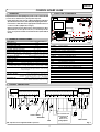 3
3
-
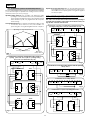 4
4
-
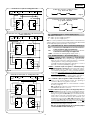 5
5
-
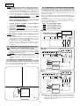 6
6
-
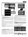 7
7
-
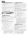 8
8
-
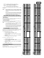 9
9
-
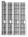 10
10
-
 11
11
-
 12
12
-
 13
13
-
 14
14
-
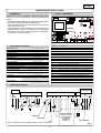 15
15
-
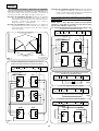 16
16
-
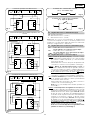 17
17
-
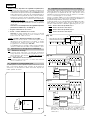 18
18
-
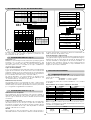 19
19
-
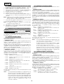 20
20
-
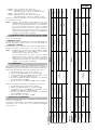 21
21
-
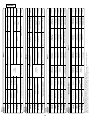 22
22
-
 23
23
-
 24
24


Genius JA388 Istruzioni per l'uso
- Categoria
- Gate Opener
- Tipo
- Istruzioni per l'uso
in altre lingue
- English: Genius JA388 Operating instructions
- español: Genius JA388 Instrucciones de operación
- Deutsch: Genius JA388 Bedienungsanleitung
Documenti correlati
-
Genius JA592 Istruzioni per l'uso
-
-
-
-
-
-
-
Genius JA574 Istruzioni per l'uso
-
-