Montarbo 458S Manuale del proprietario
- Categoria
- Altoparlanti
- Tipo
- Manuale del proprietario
La pagina si sta caricando...

458S
2
IMPORTANT ! Safety instructions
The lighting ash with arrowhead symbol within an equilateral
triangle, is intended to alert the user to the presence of
uninsulated "dangerous voltage" within the product's
enclosure, that may be of sufcient magnitude to constitute
a risk of electric shock to humans.
The exclamation point within an equilateral triangle, is
intended to alert the user to the presence of important
operating and maintenance (servicing) instructions.
WARNING !
In order to protect your own and others' safety and
to avoid invalidation of the warranty of this product,
please read this section carefully before operating
this product.
- This product has been designed and manufactured
for being operated as powered mixing console in
the applications tipical of a sound reinforcement
system or of a sound recording system. Operation
for purposes and in applications other than these
has not been covered by the manufacturer in the design
of the product, and is therefore to be undertaken at
end user's and/or installer's sole risk and responsability.
To avoid the risk of re and/or electric shock:
• Never expose this product to rain or moisture,
never use it in proximity of water or on a wet
surface. Never let any liquid, as well as any object,
enter the product. In case, immediately disconnect
it from the mains supply and refer to servicing
before operating it again.
• Before connecting this product to the mains
supply, always make sure that the voltage on the mains
outlet corresponds to that stated on the product.
• This product must be connected only to a
grounded mains outlet complying to the safety
regulations in force via the supplied power cable. In
case the power cable needs to be substituted, use
exclusively a cable of the same type and characteristics.
• Never place any object on the power cable.
Never lay the power cable on a walkway where
one could trip over it. Never press or pinch it.
• Never install the product without providing
adequate airow to cool it. Never obstruct the air
intake openings on it.
• In case the external fuse needs replacement,
substitute it only with one of the same type and rating,
as stated on the product.
• Always make sure the On/Off switch is in its 'Off'
position before doing any operation on the
connections of the product.
• Before attempting to move the product after it
has been installed, remove all the connections.
• To disconnect the power cable of this product
from the mains supply never pull the cable directly
instead, hold the body of the plug rmly and pull
it gently from the mains supply outlet.
CAUTION !
This product does not contain user serviceable parts.
To prevent re and/or electrical shock, never
remove its cover. Maintenance and servicing must
be carried out only by Elettronica Montarbo srl or
the ofcial Montarbo Distributor in your State or by
qualied personnel specically authorized by them.
- Before placing the product on a surface of any
kind, always make sure that its shape and load
rating will safely match the product's size and weight.
- To avoid shocks always reserve a protected area
with no access to unqualied personnel as
installation site of the product. In case the product
is used near children and animals closest supervision
is necessary.
- This product in combination with headphones or
speakers can generate very high acoustic pressures
which are dangerous for the hearing system.
Do not operate for a long period of time at a high
or unconfortable volume level.
Never expose children to high sound sources !
IMPORTANT ! Normes de securité
Le symbole représentant un éclair se terminant par une èche
dans un triangle équilatéral indique la présence dans le boîtier
d'un 'voltage dangereux' non isolé, sufsamment important
pour constituer un risque d'électrocution.
Le symbole représentant un point d'exclamation dans un triangle
équilatéral renvoie l'utilisateur à des instructions importantes
relatives au fonctionnement et à l'entretien de l'appareil.
ATTENTION !
Dans l'intérêt de la sécurité personnelle et des tiers,
et pour ne pas invalider la garantie, nous recom-
mandons de lire attentivement ces recommandations
avant d'utiliser le produit.
- Cet appareil a été conçu et construit pour être utilisé
en tant que table de mixage amplié dans le contexte
typique d'un système d'amplication sonore et/ou
d'un système d'enregistrement sonore. L'utilisation
pour des objectifs différents de ceux-ci n'est pas
contemplée par le constructeur et
s'effectue par conséquent sous la responsabilité directe
de l'utilisateur/installateur.
Pour eviter le risque d'incendie et/ou d'electrocution:
• Ne pas exposer le produit à la pluie, ne pas l'utiliser
en présence d'humidité élevée ou près de l'eau. Ne pas
laisser pénétrer de liquide à l'intérieur de l'appareil,
ni aucun autre objet solide.
Dans le cas contraire déconnecter immédiatement
l'appareil du réseau électrique et s'adresser à un service
d'assistance qualié avant de le réutiliser.
• Avant de relier l'appareil au réseau électrique,
s'assurer que la tension corresponde à celle
indiquée sur l'appareil.
• Relier cet appareil exclusivement à une prise de
courant dotée de contact de terre répondant aux
normes de sécurité en vigueur au moyen du câble
d'alimentation en dotation. Au cas où le câble devrait
être remplacé, utiliser exclusivent un câble possédant
les mêmes caractéristiques.
• Ne poser aucun objet sur le câble d'alimentation.
Ne pas le positionner dans des lieux où il pourrait
entraver les déplacements ou provoquer des chutes.
Ne pas l'écraser ni le piétiner.
• Installer cet appareil en prévoyant un espace suf-
samment grand autour pour la circulation de l'air
nécessaire au refroidissement. Ne pas obstruer les
ouvertures ou les prises d'air présentes sur l'appareil.
• En cas de remplacement du fusible extérieur,
utiliser exclusivement un fusible de caractéristiques
identiques, comme indiqué sur l'appareil.
• Avant d'effectuer toute opération de branchement,
s'assurer que l'interrupteur d'allumage de l'appareil
soit en position 'Off' (éteint).
• Avant d'effectuer tout déplacement du produit
déjà installé ou en
service, enlever tous les câbles de branchement.
• Pour déconnecter l'appareil du réseau électrique, ne
jamais tirer le câble mais le saisir par le connecteur.
ATTENTION !
Cet appareil ne contient pas de pièces intérieures
destinées à l'intervention directe de la part de
l'utilisateur. Pour éviter le risque d'incendie et/ou
d'électrocution, ne pas l'ouvrir.
Pour toute intervention d'entretien ou de réparation,
s'adresser à Elettronica Montarbo srl ou au distri-buteur
de votre état ou à un personnel hautement qualié,
spéciquement signalé par l'importeur.
- Au moment de la prédisposition de l'appareil à
l'utilisation, s'assurer que la forme et la capacité
de la surface d'appui soient appropriées.
- Pour éviter les chocs utiliser pour l'installation du
produit un lieu sûr comme une zone protégée d'accès
interdit au personnel non qualié. Au cas où l'appareil
serait utilisé en présence d'enfants et d'animaux, une
surveillance étroite est nécessaire.
- Cet appareil utilisé avec des écouteurs ou des bafes
est en mesure de générer des pressions
acoustiques très élevées, dangereuses pour la santé
du système auditif. Par conséquent, éviter de l'utiliser
longtemps à des niveaux acustiques élevés.
Ne pas exposer les enfants à des sources
sonores élevées !
IMPORTANTE ! Norme di sicurezza
Il lampo con la freccia inserito in un triangolo equilatero avvisa
l'utilizzatore circa la presenza di 'tensione pericolosa', senza
isolamento, all'interno dell'apparecchio che potrebbe essere
sufcientemente alta da generare il rischio di scossa elettrica.
Il punto esclamativo inserito in un triangolo equilatero
avvisa l'utilizzatore circa la presenza di importanti istruzioni
per l'utilizzo e per la manutenzione del prodotto
ATTENZIONE !
Nell'interesse della propria e della altrui sicurezza,
e per non invalidare la garanzia, si raccomanda una
attenta lettura di questa sezione prima di adoperare
il prodotto.
- Questo apparecchio è stato progettato e costruito per
venire utilizzato come mixer amplicato nel contesto
tipico di un sistema di amplicazione sonora, e/o di
un sistema di registrazione sonora.
L'utilizzo per scopi diversi da questi non è contemplato
dal costruttore, ed avviene pertanto sotto la diretta
responsabilità dell'utilizzatore.
Per evitare il rischio di incendio e/o di folgorazione:
• Non esporre il prodotto alla pioggia non utilizzarlo
in presenza di elevata umidità o vicino all'acqua.
Non lasciare penetrare all'interno dell'apparecchio
alcun liquido, né alcun oggetto solido. In caso ciò
avvenga, scollegare immediatamente l'apparecchio
dalla rete elettrica e rivolgersi ad un servizio di assi-
stenza qualicato prima di adoperarlo nuovamente.
• Prima di collegare l'apparecchio alla rete elettrica
assicurarsi che la tensione corrisponda a quella indicata
sull'apparecchio stesso.
• Collegare questo apparecchio esclusivamente ad
una presa di corrente dotata di contatto di terra
rispondente alle norme di sicurezza vigenti tramite
il cavo di alimentazione in dotazione. Nel caso in cui
il cavo necessiti di sostituzione, utilizzare esclusiva-
mente un cavo di identiche caratteristiche.
• Non appoggiare alcun oggetto sul cavo di alimen-
tazione. Non posarlo dove possa costituire intralcio
e causare inciampo. Non schiacciarlo, non calpestarlo.
• Installare questo apparecchio prevedendo ampio
spazio circostante per un'abbondante circolazione
d'aria, necessaria al raffreddamento. Non ostruire le
aperture o le prese d'aria presenti sull'apparecchio.
• In caso di sostituzione del fusibile esterno, utilizzare
esclusivamente un fusibile di caratteristiche identiche,
come riportato sull'apparecchio.
• Prima di effettuare qualsiasi operazione di colle-
gamento, assicurarsi che l'interruttore di accensione
dell'apparecchio sia in posizione 'Off'.
• Prima di effettuare qualsiasi spostamento del pro-
dotto già installato o in funzione, rimuovere
tutti i cavi di collegamento.
• Per scollegare l'apparecchio dalla rete elettrica,
non tirare mai lungo il cavo, ma afferrarlo sempre
per il connettore.
ATTENZIONE !
Questo apparecchio non contiene parti interne desti-
nate all'intervento diretto da parte dell'utilizzatore.
Per evitare il rischio di incendio e/o folgorazione,
non aprirlo. Per qualsiasi intervento di manutenzione
o riparazione, rivolgersi a personale altamente qua-
licato e/o alla Casa costruttrice.
- Nel predisporre l'apparecchio all'utilizzo, assicurarsi
che la forma e la portata della supercie di appoggio
siano idonee a sostenerlo.
- Per evitare urti riservate come luogo per l'istalla-zione
del prodotto un'area protetta inaccessibile
a personale non qualicato. Qualora l'apparecchio
venga utilizzato in presenza di bambini e animali,
si rende necessaria una strettissima sorveglianza.
- Questo prodotto utilizzato insieme a cufe o a casse
acustiche è in grado di generare pressioni acustiche
molto elevate, pericolose per la salute
del sistema uditivo. Evitarne quindi l'utilizzo ad
elevati o fastidiosi livelli acustici.
Non esporre i bambini a forti sorgenti sonore !
WICHTIG ! Unfallverhütungsvorschriften
Das Blitzsymbol mit Pfeilspitze innerhalb eines gleichschenk-ligen
Dreiecks warnt Benutzer vor dem Vorhandensein nicht-isolierter
"gefährlicher Netzspannungen" im inneren des Produkts die
so stark sein können, daß für Menschen die Gefahr eines
Stromschlags besteht.
Das Ausrufezeichen innerhalb eines gleichschenkligen Dreiecks
macht Benutzer auf das Vorhandensein wichtiger Betriebs-
und Wartungsanleitungen aufmerksam
ACHTUNG !
Im Interesse Ihrer eigenen Sicherheit und der Sicher-
heit anderer und um die Garantie nicht zu gefährden,
sollte der vorliegende Abschnitt vor Gebrauch des
Produkts aufmerksam gelesen werden.
- Dieses Gerät wurde für den Gebrauch als Mischver-
stärker im Rahmen typischer Anwendungen von
Lautverstärkungssystemen und/oder Tonaufnahme-
systemen konzipiert und konstruiert. Der Gebrauch
zu anderen als den genannten Zwecken ist vom
Hersteller nicht vorgesehen und erfolgt somit unter
direkter Verantwortung des Benutzers/Installateurs.
Zur Vermeidung der Gefahr von Bränden und/oder
Elektrischen schlägen:
• Dieses Produkt nicht Regen oder Feuchtigkeit aus-
setzen und nicht in der Nähe von Wasser gebrauchen.
Verhindern, daß in das Gerät Flüssigkeiten oder
Gegenstände eindringen. Sollte dies dennoch
geschehen, unverzüglich das Gerät vom Stromnetz
trennen und vor der erneuten Inbetriebnahme durch
einen qualizierten Servicetechniker überprüfen lassen.
• Vor dem Anschließen des Geräts an das Stromnetz
sicherstellen, daß die Netzspannung mit der auf dem
Gerät angegebenen Nennspannung übereinstimmt.
• Das Gerät ausschließlich mit dem mitgelieferten
Netzkabel an eine Steckdose mit Schutzkontakt
anschließen die den geltenden Sicherheitsvoschriften
entspricht. Muß das Netzkabel ersetzt werden,
aus schließlich ein Netzkabel mit identischen
Eigenschaften verwenden.
• Keine Gegenstände auf dem Netzkabel abstellen. Das
Netzkabel so verlegen, daß es kein Hindernis darstellt
und keine Stolpergefahr besteht. Das Netzkabel nicht
quetschen und nicht darauf treten.
• Bei der Installation genug freien Raum um das Gerät
lassen, um eine ausreichende Luftzirkulation für die
Kühlung zu gewährleisten. Die Lüftungs-
und Ausaugöffnungen nicht verdecken.
• Muß die externe Sicherung ausgetauscht wer-
den, ausschließlich eine Sicherung mit identischen
Eigenschaften gemäß den Angaben auf dem Gerät
verwenden.
• Vor dem Anschließen des Geräts sicherstellen,
daß sich der Ein/Aus-Schalter in Schaltstellung 'Off'
(AUS) bendet.
• Vor dem Transport des schon installierten oder
schon in Betrieb bendlichen Geräts zunächst alle
Anschlußleitungen lösen.
• Zum Ausstecken des Netzkabels aus der Steckdose
niemals am Netzkabel ziehen, sondern stets den
Stecker selbst greifen.
ACHTUNG !
Dieses Gerät enthält keine Teile, bei denen ein direkter
Eingriff seitens des Benutzers vorgesehen ist. Das
Gerät niemals öffnen, um die Gefahr von Bränden und
elektrischen Schlägen zu vermeiden. Für Wartungs-
und Reparatureingriffe stets
Elettronica Montarbo srl oder den für Ihr Land
zuständigen Importeur oder einen vom Importeur
autorisierten Fachmann zu Rate ziehen.
- Beim Aufstellen des Geräts sicherstellen, daß Art
und Tragfähigkeit der Standäche für das Gerät
geeignet sind.
- Zur Vermeidung von Stößen das Gerät nur an einem
geschützten und Unbefugten nicht zugänglichen Ort
aufstellen. Wenn das Gerät in Gegenwart von Kindern
oder Haustieren betrieben wird, ist
eine strikte Überwachung erforderlich.
- Der Betrieb des Gerätes mit Kopfhörern oder
Lautsprechern kann sehr hohe Schalldrücke erzeugen,
die zu Gehörschäden führen können. Vermeiden Sie
daher das Gerät über lange Zeit mit zu hoher oder
unerträglicher Lautstärke benutzen.
Niemals Kinder starken Schallemissionen
aussetzen !

458S
3
INHALTSVERZEICHNIS:
Seite
4-5
Fig. 1: Vorder-und-Hinter-
Ansicht
6
Echo-Teil
7
Wichtig !
8
Der graphische Equalizer
ANSCHLUßBEISPIELE
9
Fig.2: Verstärker-Ausgang
(Anschluß von Boxen)
10
Fig. 3: Monitor-Ausgang
10
Fig. 4: 'master pre-out'
Ausgang
11
Fig. 5: 'send & return'
11
Fig. 6: 'aux' Eingang
12
Fig. 7: 'tape' Buchse
(Tonband-Anschluß)
13
Technische Daten
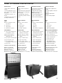
PACKUNGSINHALT
◗ 8-Kanal-Mischer 458S
◗ Netzkabel
◗ Bedienungsanleitung
◗ Garantiebescheinigung
◗ EG-Konformitätserklärung
TABLE OF CONTENTS:
Page
4-5
Fig. 1: front and rear
panels
6
Echo section
7
Important !
8
Graphic equalizer
CONNECTIONS
9
Fig. 2: amplier output
(speakers connection)
10
Fig. 3: monitor output
10
Fig. 4: 'master pre-out'
output
11
Fig. 5: 'send & return'
11
Fig. 6: 'aux' input
12
Fig. 7: 'tape' socket
(hooking up a tape recorder)
13
Specications
PACKAGE CONTENTS
◗ 8-channel mixer 458S
◗ Power supply cable
◗ Owner’s manual
◗ Warranty certicate
◗ CE declaration of conformity
INDICE:
Pagina
4-5
Fig.1: pannello frontale
e posteriore
6
Sezione eco
7
Importante !
8
Equalizzatore graco
COLLEGAMENTI
9
Fig.2: uscita amplicatore
(collegamento casse)
10
Fig. 3: uscita monitor
10
Fig. 4: presa di uscita
'master pre-out'
11
Fig. 5: prese 'send & return'
11
Fig. 6: ingresso 'aux'
12
Fig. 7: presa 'tape'
(collegamento registratore)
13
Dati tecnici
CONTENUTO DELL’IMBALLO
◗ Mixer a 8 canali 458S
◗ Cavo di alimentazione
◗ Manuale istruzioni
◗ Certicato di garanzia
◗ Dichiarazione di conformità CE
458S
8-CHANNEL POWERED MIXER
OWNER'S MANUAL
• Micro (balanced) and line
inputs
• Digital Echo/Halo (24-bit A/D
to D/A conversion / Montarbo
custom chip)
• 9 band-Graphic Equalizer
• extremely portable and easy
to use
BEDIENUNGS-ANLEITUNG
• Eingänge für symmetrische
Mikrophone und Line
• Digital-Echo/Hall (24 Bit-
Montarbo custom chip für
A/D-D/A Auösung)
• 9-Band -Graphik-Equalizer
• Leicht transportierbar,
äusserst einfach zu bedienen
MANUEL D'ISTRUCTIONS
• Entrées micros (balancées)
et ligne
• Echo/Halo digital (conversion
a 24 bits)
• Egaliseur graphique à
9 bandes
• Transport très pratique
MANUALE D'USO
• Ingressi Micro (bilanciati)
e Linea
• Eco/Alone Digitale (conver-
sione a 24 bit / chip originale
Montarbo)
• Equalizzatore Graco a 9
bande
• praticissimo per il trasporto e
di semplice utilizzazione
INDEX:
Page
4-5
Fig. 1: face avant et face
arriere
6
Section echo
7
Important!
8
Egaliseur graphique
EXEMPLES DE RACCORDEMENTS
9
Fig.2: sortie amplicateur
(raccordement d’enceintes)
10
Fig. 3: sortie monitor
10
Fig. 4: sortie 'master pre-out'
11
Fig. 5: 'send & return'
11
Fig. 6: éntrée 'aux'
12
Fig. 7: prise 'tape'
(Raccordement à un
magnétophone stéréo)
13
Données techniques
CONTENU DE L'EMBALLAGE
◗ Table de mixage 8 canaux 458S
◗ Câble d'alimentation
◗ Manuel d'instructions
◗ Certicat de garantie
◗ Declaration de conformité CE
La pagina si sta caricando...

458S
5
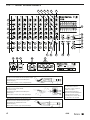
FRONT & REAR PANELS
PANNELLO FRONTALE
1 Volume MANDATA ECO.
Permette di regolare la quantità di
effetto (Eco/Alone digitale incorpora-
to) da aggiungere al segnale di ingres-
so di quel canale. Dipende dai
controlli di tono, indipendente dal
volume.
2 Volume MANDATA MONITOR.
Permette di regolare il livello del se-
gnale del canale nell’uscita miscelata
monitor. Dipende dai controlli di tono
del canale, indipendente dal volume.
3 VOLUME del canale.
4 Controllo toni ALTI. Regola la
quantità di accentuazione o attenua-
zione delle frequenze alte. Girando
la manopola in senso orario aumen-
tano i toni alti, in senso antiorario
diminuiscono.
5 Controllo toni BASSI. Regola la
quantità di accentuazione o attenua-
zione delle frequenze basse. Girando
la manopola in senso orario aumen-
tano i toni bassi, in senso antiorario
diminuiscono.
6 Ingresso LINEA sbilanciato
(per strumenti, microfoni ad alta
impedenza ecc...).
7 Ingresso MICRO bilanciato
(per microfoni a bassa impedenza)
8 SEZIONE ECO - Vedi pag. 6.
SEZIONE MASTER
9 EQUALIZZATORE graco
a 9 bande - Vedi pag. 8.
10 Volume MASTER. Regola la poten-
za di uscita totale dell’amplicatore.
11 Volume MONITOR. Regola il
volume dell’uscita Monitor.
12 Presa Jack uscita MONITOR (pre-
amplicata), per collegare monitor
amplicati o nali di potenza.
Vedi g. 3.
13 Presa Jack uscita MASTER
(pre-amplicata), per collegare
casse acustiche amplicate o nali
di potenza. Vedi g. 4
14 Controllo di volume per
l’ingresso AUX (ausiliario) e per le
prese TAPE in.
15 Ingresso AUSILIARIO (livello max.
-10dB). Permette il collegamento di
qualsiasi tipo di sorgente sonora
come ad esempio un mixer ausiliario,
un microfono ecc..... Vedi g. 6.
16 Prese PIN ingresso/uscita per il
collegamento di un registratore
stereo - Vedi g. 7.
17 Quattro prese jack di USCITA
dell’amplicatore incorporato.
L’impedenza di carico minima è di
2 ohm. Ciò vi consente di collegare
2 o 4 casse da 8 ohm - Vedi g. 2.
18 Prese SEND (Pre-out) e RETURN
(Main-in). Permettono il collegamen-
to di un effetto esterno - Vedi g. 5.
19 Presa di rete a vaschetta con
fusibile incorporato.
20 Presa di terra.
21 Interruttore di rete.
FRONT PANEL
1 ECHO SEND volume.
Determines how much effect signal
from the internal effect (Digital Echo/
Halo) is added to the input signal
of the channel (Pre volume/post tone
control).
2 MONITOR SEND volume. Sets
the level of that input channel in the
monitor mixed output (Pre volume /
post tone controls).
3 Channel VOLUME.
4 TREBLE tone control - adjusts the
amount of boost or cut in the high
frequency range. Turning the control
clockwise, increases the amount of
treble, counter-clockwise decreases
it.
5 BASS tone control - adjusts
the amount of boost or cut in the
bass frequency range. Turning the
control clockwise, increases the
amount of bass, counter- clockwise
decreases it.
6 Unbalanced LINE input
(for instruments, high impedance
microphones etc..).
7 Balanced MICRO input (for low
impedance microphones).
8 ECHO SECTION - See page 6.
MASTER SECTION
9 9-band graphic EQUALIZER.
See page 8.
10 MASTER volume. It adjusts the
total power output of the amplier.
11 MONITOR volume. It adjusts the
Monitor output.
12 MONITOR output (preamp.) jack
socket for connection to powered
stage monitors or power units.
See g. 3.
13 MASTER output jack socket for
connection to powered PA speaker
enclosures (up to 10, parallel
connected) - See g. 4.
14 Volume control for the
AUXILIARY input and for the TAPE in.
15 AUXILIARY input (max. input
level -10 dB) allows connection of
any sound source, such as a
microphone, an auxiliary mixer etc,
having a suitable output level.
See g. 6
16 PIN in / out sockets for
connection of a stereo tape recorder.
See g. 7
17 4 jack sockets for the OUTPUT of
the internal power amplier.
The minumum impedance is 2 ohms.
This allows you to connect 2 or 4
8-ohms speaker enclosures.
See g. 2.
18 SEND (Pre-out)/ RETURN (Main-
in) sockets. They allow connection
of an external effect device.
See g. 5.
19 I.E.C. power supply socket and
mains fuse.
20 Ground socket.
21 Mains power switch.
VORDERSEITE
1 ECHO-SEND-Regler: er reguliert
den Effektanteil pro-Kanal des
eingebauten Echo-Halls.
Er liegt hinter den Ton-Reglern
und vor der Lautstärke des Kanals.
2 MONITOR-SEND-Regler: reguliert
den Signal-Pegel, der den Monitoren
zugeführt wird. Er liegt hinter den
Ton-Reglern und vor der Lautstärke
des Kanals.
3 Kanal-LAUTSTÄRKE-Regler.
4 HÖHEN-Regler: regelt den Anteil
der hohen Frequenzen. Durch Drehen
des Knopfes nach rechts verstärken
sich die Höhen, durch Drehen nach
links schwächen sich diese ab.
5 BASS-Regler: regelt die tiefen
Frequenzen. Durch Rechts sdrehen
des Knopfes werden die Bässe
angehoben, nach links abgesenkt.
6 Asymmetrischer LINE Eingang
für Instrumente oder hochohmige
Mikrophone.
7 Symmetrischer MICRO Eingang
für niederohmige Mikrophone.
8 ECHO -Teil - Siehe Seite 6.
MASTER-TEIL
9 9-bandiger Graphik-EQUALIZER.
Sehe Seite 8.
10 SUMMEN-Lautstärke-Regler:
regelt die Leistung des Verstärkers.
11 MONITOR-Summen-Regler:
bestmmt die Lautstärke des Monitor-
Ausgangs.
12 MONITOR-Ausgangs buchse
(Vorverstärker): zum Anschließen von
aktiven Monitoren oder Endstufen.
Siehe Abb. 3.
13 LINE-Ausgangsbuchse
(Vorverstärker): zum Anschließen
von aktiven Lautsprecher-Boxen oder
Endstufen (bis zu 10 Stück parallel).
Siehe Abb. 4.
14 Lautstärke-Regler für den AUX-
Eingang und für die Tape In Buchsen.
15 AUX-Eingang (max. Pegel
-10 dB): ermöglicht den Anschluß
jeder Art von Tonquellen wie z.B.
einem Sub-Mixer, einemMikrophon
etc.... Siehe Abb. 6.
16 CHINCH-Buchsen für den
Anschluß eines Stereo Tonband
gerätes. Siehe Abb. 7.
17 4 Klinkenbuchsen für den
Endstufen-AUSGANG. Die Mindest-
Impedanz beträgt 2 Ohm.
Zum Anschließen von z.B 2 oder 4
Lautsprecher-Boxen an 8-Ohm.
Siehe Abb. 2.
18 Send (Pre-Out) / Return (Main-In)-
Buchsen: sie ermöglichen den
Anschluß eines externen Effekt-
Gerätes. Siehe Abb. 5.
19 Euro-Netzstecker mit
eingebauter Sicherung.
20 Erdungsbuchse.
21 Netzschalter.
PANNEAU FRONTAL
1 Volume DEPART ECHO.
Permet de règler la quantité d’effet
(Echo/Halo incorporè) à ajouter au
signal d’entrèe de la voie (avant
volume / aprés contrôles de tonalitè)
2 Volume DEPART MONITOR
(avant
volume/aprés contrôles de tonalitè).
Réglent le niveau du signal de la voie
sur la sortie monitor.
3 VOLUME de la VOIE.
4 TREBLE: règle la quantité
d'accentuation ou d'atténuation
des fréquences aigues. En tournant
le bouton dans le sens des aiguilles
d'une montre les tonalités aigues
augmentent, dans le sens contraire
elles diminuent.
5 BASS règle la quantité
d'accentuation ou d'attenuation
des fréquences graves. En tournant
le bouton dans le sens des aiguilles
d'une montre les tonalités graves
augmentent, dans le sens contraire
elles diminuent.
6 Entrée LIGNE asymmetrique
de la voie, peut être utilisée comme
retour d’effet exterieur.
7 Entrèe MICRO symmetrique
(pour micros à basse impédance).
8 SECTION ECHO - Voir page 6.
SECTION SORTIE
9 EGALISEUR graphique 9-bandes.
Voir page 8.
10 Volume MASTER.
Règle la puissance de sortie totale
de l’amplicateur.
11 Volume MONITOR.
Règle le volume de la sortie Monitor.
12 Prise Jack sortie MONITOR,
(preampliée), pour raccorder des
monitors ampliés ou amplicateurs
de puissance - Voir g. 3.
13 Prise Jack sortie MASTER (pream-
plièe), pour raccorder des enceintes
acoustiques ampliées ou amplica-
teurs de puissance - Voir g.4
14 Contrôle de volume pour l’entrée
AUX, (auxiliaire) et pour les prises
TAPE in.
15 Entrèe AUXILIAIRE (Niveau max
-10dB). Permet le raccordement de
n’importe quel genre de source
sonore comme, par exemple, un
mixeur auxiliaire, un microphone,
etc… - voir g. 6.
16 Prises PIN entrée/sortie pour le
raccordement d’un magnétophone
stereo - Voir g.7.
17 Quatre prises Jack de SORTIE de
l’amplicateur incorporé. L’impédan-
ce de charge minimum est de 2 ohms.
Ceci vous permet de raccorder jusq’à
quatre enceintes de 8 ohms ou deux
de 8 ohms - voir g. 2.
18 Prise SEND (Pre-out)/ RETURN
(Main-in). Permettent le raccordement
d’un effet extérieur - voir g. 5.
19 Prise de réseau avec fusible incor-
poré.
20 Prise de terre.
21 Interrupteur de réseau.

458S
6
ECHO SECTION
SEZIONE ECO
L’Eco Digitale incorporato utilizza un
chip originale Montarbo a 24 bit per
la conversione A/D-D/A.
Grazie alle sosticate tecnologie
circuitali di cui esso dispone, è in
grado di produrre effetti di ECO e
ALONE con bassissimo rumore e
notevole gamma dinamica.
A 3 indicatori LED consentono il
controllo visivo del segnale di ingresso
all’eco per evitare distorsioni:
• il primo (da sinistra) si accende
premendo uno dei due pulsanti di
preselezione ritardo,
• il secondo indica la presenza di
segnale,
• il terzo (rosso) è l’indicatore di picco.
Continuamente acceso indica sovrac-
carico di segnale; quando lampeggia
leggermente la regolazione è normale.
B Controllo RIPETIZIONI. Regola la
durata dell’effetto.
C Volume MANDATA MONITOR
(dipende dal volume eco). Permette
di regolare il livello del segnale eco
nell’uscita monitor.
D Controllo di VOLUME.
E Due pulsanti permettono di
selezionare i due ritardi separati.
• premendoli entrambi si ottiene
l’effetto 'ALONE/RIVERBERO'.
F FILTRO PASSA-BASSO.
Premendo questo pulsante si attiva
il ltro che attenua le frequenze al
di sopra dei 3000Hz.
G Controllo continuo del RITARDO.
H Presa jack per il comando a pe-
dale dell’eco.
☞ N.B: Tanti sono gli effetti ottenibili
e diverse le esigenze di ogni singolo
utilizzatore. Sarebbe perciò impos-
sibile (ed anche limitativo!) indicare
tutti gli effetti particolari.
Iniziate con le regolazioni sotto indi-
cate per familiarizzare con il vostro
eco digitale. È talmente semplice da
utilizzare che sarete presto in grado
di creare i 'vostri' effetti.
• Portare il volume dell’eco alla
posizione centrale.
• Scegliere il ritardo premendo uno
dei due pulsanti di preselezione ritar-
do. Premendoli entrambi si
ottiene l’effetto 'Alone' (riverbero).
• Regolare il ritardo prescelto con
il comando DELAY e la durata
dell’effetto per mezzo del comando
REPEATS.
• Regolare i volumi di mandata
Eco nei canali dove si voglia avere
l’effetto. Per una regolazione
ottimale controllare il LED rosso.
Quando lampeggia leggermente è
normale. Se continuamente acceso
indica sovraccarico di picco ed è
opportuno ridurre il volume della
mandata eco nei singoli canali.
ECHO-TEIL
Das eingebaute Digital-Echo,
beinhaltet ein 24-bit Montarbo
custom chip und erzeugt Echo-
und Hall-Effekte bei niedrigstem
Geräuschpegel und breitem
Frequenz-Spektrum.
A 3 LEDs ermöglichen die optische
Kontrolle des Echo-Eingangssignals,
um Verzerrungen zu vermeiden:
• das erste (von links) leuchtet beim
Drücken einer der beiden Echo-
Vorwahltasten auf,
• das zweite zeigt an, daß ein Signal
anliegt,
• das dritte (rote Taste) ist die
Übersteuerungsanzeige.
Ununterbrochenes Aueuchten zeigt
Übersteuerung an, gelegentliches
Aueuchten ist normal.
B HALLDAUER-Regler: bestimmt
die Effekt-Länge.
C MONITOR-SEND-Regler (liegt
hinter dem Echo-Regler): ermöglicht
die Einstellung des Echo-Teils am
Monitor-Ausgang.
D Echo-STÄRKE-Regler.
E Durch wahlweise drücken dieser
Tasten können ZWEI Echo/Hallzeiten
gewählt werden: 1 = 200 ÷ 600ms /
2 = 130 ÷ 400ms
• werden beide Tasten gleichzeitig
gedrückt, wird ein NACHHALL-
Effekt (HALO) erzeugt.
F HÖHEN-FILTER-TASTE: durch
Drücken dieser Taste werden die
Echo-Frequenzen über 3000Hz abge-
schnitten.
G DELAY-Regler zur Einstellung
der Einzelecho-Abstände.
H Klinkenbuchse für den Echo-
Fuß-Schalter.
☞ N.B: Die Effektmöglichkeiten des
integrierten Echo/Hallgeräts sind
so zahlreich, daß sie an dieser Stelle
nicht detailiert aufgeführt werden
können. Beginnen Sie einfach mit
den nachfolgend beschriebenen
Grundeinstellung und nden
Sie dadurch zu den von Ihnen gewün-
schten Einstellungen.
Sie werden sicher bald zu Ihren
eigenen Klängen nden.
• Den Echo-Stärke-Regler in
Mittelstellung bringen.
• Echo-Abstand durch Drücken
einer der beiden Tasten festlegen.
*Das Drücken beider Tasten ergibt
Hall-Effekt.
• Verzögerungszeit und Nachhall-
Dauer einstellen.
• Die Echo-Send-Regler bei den
Kanälen, bei denen Echo gewünscht
wird, einstellen. Achten Sie auf die
rote LED-Anzeige im Echoteil:
Flackern zeigt normale Aussteuerung
an; ununterbrochenes Aueuchten
zeigt Übersteuerung.
an. Es empehlt sich dann, die
Echo-Send-Regler der einzelnen
Kanäle zurückzudrehen.
SECTION ECHO
L’écho digital incorporé (avec puce
original Montarbo à 24 bits) est le
fruit de techno logies de circuit sophi-
sitquèes et peut produire des effets
d’ECHO / HALO de bruit très faible et
de remarquable gamme dynamique.
A Trois indicateurs LED permettent
le contrôle visuel du signal en entrée
à l’écho pour éviter distorsion:
• le premier (à partir de la gauche)
s’allume si l’on pousse une des deux
touches de pré-sélection retard,
• le deuxième indique la présence
du signal,
• le troisième (rouge) est l’indicateur
PEAK. Il est allumé de façon xe cela
indique la surcharge du signal; il cli-
gnote légèrement quand le réglage
est normal.
B Contrôle REPETITION. Régle la
durée de l’effet.
C Volume DEPART MONITOR
(dépend du volume écho).
Permet de régler le niveau du signal
écho à la sortie Monitor.
D Contrôle de VOLUME.
E Deux touches permettent de
sélectionner les DEUX retard séparés.
• En les poussant toutes les deux
simultanément,on obtient l’èffet
HALO/REVERB.
F FILTRE LOW-PASS. En poussant
sur cette touche, on active le ltre qui
atténue les fréquences au dessus de
3000Hz.
G Contrôle continu du RETARD.
H Prise pour la commande à pédale
de l’écho.
☞ N.B.: Les effets que l’on peut
obtenir sont vraiment nombreux
et les exigences de chaque usager
également. Il serait donc impossible
(et même limitatif) d’indiquer tou les
effets particuliers. Commencez donc
par les réglages indiqués ci-dessous
pour vous familiariser avec votre écho
digital. Il est tellement simple à utiliser
que vous serez vite capables de créer
'vos' propres effets.
• Porter le volume de l’écho en
position centrale.
• Choisir le retard en poussant une
des deux touches de présélection re-
tard. En les poussant toutes les deux,
on obtient l’effet 'HALO' (réverbère)
• Régler le retard choisit au paravant
par le moyen de la comman de DELAY
et la durée de l’effet par le moyen de
REPEATS.
• Régler les volumes de départ Echo
pour les canaux où l’on désire l’effet.
Pour un réglage optimal, contrôler
l’indicateur LED rouge sur la section
Echo. Un léger clignotement est
normal. Allumé de façon xe, il
indique une surcharge de PEAK et
il est alors fortement conseillé de
réduire le volume du départ écho
pour chaque canal.
ECHO SECTION
The internal Digital Delay, utilizing
a 24-bit Montarbo custom chip for
A/D-D/A conversion, produces ECHO
and HALO effects with very low
noise and a wide dynamic range.
A 3 LED indicators allow visual
control of the signal to avoid
distortion.
• the rst (from the left) lights when
one of the two delay preset buttons
is pushed.
• the second indicates signal presence
• the third (red) is the PEAK indicator.
If it is ON continuously it indicates
signal overload. Occasional blinking
is normal.
B REPEATS control.
C MONITOR SEND volume (Post
echo volume). Adjusts the quantity
of echo signal in the monitor mixed
output.
D Echo VOLUME control.
E TWO separate echo delays.
• simultaneous pushing of both of
them produces the 'HALO/REVERB'
effect.
F LOW-PASS FILTER pushbutton,
(pushed = on). This button allows to
cut the frequencies above 3000Hz.
G Continuous DELAY control.
H Jack socket for echo footswitch.
+ NOTE: so many are the possible
sounds and so different the individual
needs that all specic effects can not
be indicated here.
Start with the settings indicated
below to familiarize with the controls
of your digital delay. It is so easy
to use that you will soon be able to
create your 'own' sounds.
• Turn the volume control to the
middle position.
• Select one of the two echo delays,
by pushing one of the two buttons, or
the 'Halo' (reverb) effect by pushing
both of them.
• Use the DELAY control to adjust
the delay time and the REPEATS con-
trol to set the effect duration.
• Adjust 'echo send' volumes in
the channels where echo is needed.
For proper adjusting check the red
LED indicator. Occasional blinking
is normal. If it is on continuously it
indicates signal overload and it is
necessary to reduce echo send
volumes on individual channels.

458S
7
AVVERTENZE
■
Evitare fonti di calore.
■
Mai esporre l’apparecchio a piog-
gia o umidità.
■
Utilizzare cavi SCHERMATI di ele-
vata qualità per i collegamenti agli
ingressi, alle prese Send/Return e
Tape, ed all’ingresso AUX.
■
Per il collegamento delle CASSE
ACUSTICHE all’uscita dell’amplica-
tore incorporato, utilizzare sempre i
cavi forniti con le casse e comunque
cavi NON SCHERMATI, di adeguata
sezione (tutte le nostre casse vengono
fornite complete di cavi adeguati)
■
Per il collegamento di CASSE acu-
stiche AMPLIFICATE o nali
di potenza alle uscite 'monitor' e
'master pre-out', utilizzare sempre
cavi SCHERMATI di elevata qualità
(tutte le ns. casse vengono fornite
complete di cavi adeguati).
■
Collegamento alla rete:
•Utilizzare il cavo di alimentazione a
tre poli di corredo.
•Collegarlo ad una presa di corrente
dotata di contatto di terra.
•Accertarsi che la tensione di rete
corrisponda a quella indicata
sull’apparecchio.
■
Assicurarsi sempre che il volume
del canale o il volume master siano
abbassati prima di inserire o disinse-
rire microfoni e strumenti.
COLLEGAMENTI e
REGOLAZIONI INIZIALI
• Collegare le casse acustiche alle
prese di uscita.
• Collegare i microfoni e gli strumenti.
*Prima di accendere l’apparecchio,
mettere tutti i volumi al minimo ed
i cursori dell’equalizzatore a zero
(in posizione centrale).
• Accendere l’apparecchio.
• Portare i controlli di tono in posi-
zione centrale, le mandate monitor
e le mandata eco al minimo.
• Portare i volumi master, monitor
ed il volume dell’eco in posizione
centrale.
• Un canale per volta, alzare il
volume no alla posizione centrale e
regolare i toni no ad ottenere l’equa-
lizzazione ed il volume
desiderati.
• Agire sull’equalizzatore per otti-
mizzare il suono in base alle diver-
se condizioni acustiche ambientali.
• Regolare la mandate monitor di
ogni canale ed il controllo monitor
master no ad ottenere la miscela-
zione voluta.
AVIS
■
Eviter les sources de chaleur.
■
Ne jamais exposer l’appareil à la
pluie ou à l’humidité.
■
Utiliser des câbles PROTEGES de
haute qualité pour les raccordements:
aux entées micro et ligne, aux prises
Send et Tape.
■
Pour le raccordement d’ENCEIN-
TES ACOUSTIQUES aux sorties de
l'amplicateur, utiliser toujours des
câbles NON PROTEGES de section
appropriée et de haute qualité (toutes
nos enceintes sont fournies avec les
câbles appropriés).
■
Pour le raccordement de
MONITORS AMPLIFIES, de BAFFLES
AMPLIFIES ou d'amplicateurs de
puissance aux sorties 'master preout'
und 'monitor out' - utiliser toujours
des câbles PROTEGES et de haute
qualité (toutes nos enceintes sont
fournies avec les câbles appropriés).
■
Raccordement au réseau:
• Utiliser le câble d’alimentation à
trois pôles livré avec l’appareil.
• Le raccorder à une prise de
courant dotée d’un contact de terre.
• S’assurer que la tension du réseau
corresponde à celle qui est indiquée
sur le panneau.
■
S’assurer que le volume du canal ou
le volume Master soient au
minimum avant de brancher ou
de débrancher les micros ou instru-
ments.
RACCORDEMENTS et
REGLAGES INITIAUX
• Raccorder les enceintes
acoustiques aux prises de sortie de
l'amplicateur.
• Raccorder les microphones et les
instruments.
• Mettre tous les volumes au
minimum avant d’allumer l’appareil.
• Allumer l’appareil.
• Porter les contrôles de tonalité
en position centrale, les contrôles
des départs Monitor et Echo au
minimum.
• Régler les volumes Masters et
Monitors et le volume de l'Echo
en position '0'.
• Régler un canal à la fois le volu-
me, position centrale, et régler les
tonalitàs jusq’à ce qu’on obtienne
l’egalisation et le volume désiré.
• Se servir de l'égaliseur pour obtenir
le meilleur son possible en relation
avec les conditions acoustiques
differentes de l’environnement.
VORSICHTSMAßNAHMEN
■
Wärmequellen meiden.
■
Das Gerät nie dem Regen oder der
Feuchtigkeit aussetzen.
■
Nur ABGESCHIERMTE
Qualitätskabel für den Anschluß an
Mikrophon-u. Line Eingänge sowie
an die Send- und Tape-Buchsen
verwenden.
■
Zum Anschließen der
LAUTSPRECHER-BOXEN an die
eingebauten Verstärker immer
die mitgelieferten Kabel oder
UNGESCHIERMTE, passende
Qualitätskabel benutzen.
■
Zum Anschließen von AKTIV-
Lautsprecher-Boxen oder von
Endstufen an die 'Master pre-out'
und 'Monitor out'-Buchsen immer
nur ABGESCHIERMTE Qualitäts-
Kabel benützen.
■
Euro-Stecker-Anschluß:
• Verwenden Sie nur das dem Gerät
beiliegende 3-poligen Euro-Netzka-
bel, da es geerdet ist.
• Überprüfen Sie, ob die verwendete
Netzdose geerdet ist und ob die
Netzspannung der am Gerät
aufgedrückten entspricht.
■
Darauf achten, daß die Kanal-
und Master-Lautstärken vor dem
Anschließen bzw. Ausstecken von
Instrumenten immer auf 0 stehen.
DAS ANSCHLIESSEN und
EINSTELLEN DER ANLAGE
• Die Lautsprecher-Boxen an die
Ausgangs-Buchsen anschließen.
• Mikrophone und Instrumente
anschließen. Vor dem Einschalten des
Gerätes alle Lautstärke-Regler auf
die niedrigste Stellung bringen und
die Equalizer Schieberegler auf 0dB
Mitte stellen.
• Das Gerät einschalten.
• Die Ton-Regler in Mittelstellung,
Monitor-Send- und Echo-Send-
Regler auf die niedrigste Stellung
bringen.
• Lautstärke-Summen-Regler und
Monitor-Summen-Regler sowie
Echo-Stärke-Regler in Mittel
stellung bringen.
• Nacheinander jede Kanal-Laut-
stärke-Regler und Ton-Regler je nach
Wunsch aufdrehen.
• Nach Einstellen aller Kanäle die
Anlage per Equalizer an den Raum
anpassen.
• Monitor-Send-Regler aller Kanäle
und Monitor-Summen-Regler nach
Wunsch einstellen.
PRECAUTIONS
■
Avoid heat sources.
■
Never expose the unit to
moisture or rain.
■
Use high quality SHIELDED cables
for your connections to the Micro and
Line inputs, to the Send/Return and
Tape sockets and to the AUX input.
■
When connecting the SPEAKERS
to the amplier output, always use
the cables supplied with the speakers
or high quality cables (UNSHIELDED/
heavy gauge) and plugs (all our
enclosures come equipped with sui-
table cables).
■
Always use high quality SHIELDED
cables for connecting powered spea-
kers or power units to the
'master pre-out' and 'monitor out'
sockets (all our enclosures come
equipped with suitable cables).
■
Power supply connection:
• Use the three wire power cord
supplied.
• Always connect to a grounded
outlet.
• Check that mains voltage
corresponds to the voltage indicated
on the panel.
■
Always make sure that the
channel volume or the master
volume are down before plugging
or unplugging microphones and
instruments.
PRELIMINARY CONNECTIONS
and SETTINGS
• Plug the speakers into the output
jack sockets.
• Connect microphones and
instruments. Before turning the
system on, set the channel volume
controls and the master volume
control to their lowest settings and
the equalizer’s controls to the '0' mark
(centered).
• Turn the unit on.
• Turn the tone controls to the
middle position, and the monitor
and echo sends anti-clockwise to
their lowest settings.
• Turn the master volume control,
the monitor master control and the
echo volume control to the middle
position.
• One channel at a time, adjust
the volume control to the middle
position and adjust tones according
to your requirement.
• Use the graphic equalizer to
optimize the sound for the different
acoustic environments.
• Adjust the monitor send control of
each channel and the monitor master
control until you have the
required mix .
IMPORTANT !

458S
8
GRAPHIC EQUALIZER
EQUALIZZATORE GRAFICO
L’equalizzatore, se convenientemen-
te utilizzato, consente di correggere
gli effetti dell’ambiente sulla resa
timbrica dell’impianto e di ridurre
fastidiosi rientri.
Per una corretta regolazione
dell’equalizzatore, è opportuno
tenere presente i seguenti
accorgimenti:
• Non usare regolazioni con tutti
i cursori vicini ad uno degli estremi
della corsa.
Questo comporta un inutile
aumento di rumore ed una riduzione
di dinamica.
• Stabilite attentamente la posizione
migliore per le casse e per i microfoni.
Ciò vi consentirà di ridurre al mi-nimo
i rientri ancor prima di servirvi dell’e-
qualizzatore, e di eliminare
la minor quantità possibile di
frequenze dal vostro programma
sonoro.
• Con i cursori dell’equalizzatore
in posizione centrale (sullo 0) agire
sui controlli di tono di ogni canale
per ottenere la tonalità desiderata dai
singoli microfoni o strumenti.
Solo dopo avere ottenuto una
timbrica soddisfacente, regolare
l’equalizzatore per compensare le ca-
ratteristiche acustiche dell’ambiente.
In tal modo le differenze di resa tra un
ambiente e l’altro possono
essere compensate utilizzando solo
l’equalizzatore graco, senza neces-
sità di grosse variazioni delle regola-
zioni dei canali.
GRAPHIC EQUALIZER
Careful use of the graphic equalizer
can help the overall sound system
sound more natural in less than per-
fect acoustic environments and
allows to reduce feedback.
For a proper setting of the controls of
the graphic equalizer, consider
the following:
• Avoid settings with all sliders
near to one of the extremes of their
travel. This would involve a useless
increase in noise or a reduction of
dynamic range.
• Choose carefully the placement
of loudspeakers and microphones
to minimize feedback before using
the equalizer, in order to get the
most volume before feedback is
heard. Otherwise you risk removing
signicant amounts of your program
material.
• With the graphic equalizer’s
controls set to the zero mark
(centered) adjust the tone controls
of each channel until you get the tonal
color you want for each
microphone or instrument.
Once you have adjusted the tone con-
trols of each channel, start adjusting
the controls of the graphic equalizer
to compensate for the acoustic envi-
ronment and speaker
placement. This will allow you to
compensate for different acoustic
environments acting only on the
equalizer's setting with no need of
altering too much the tone controls
settings of each channel.
L'EGALISEUR GRAPHIQUE
S’il est convenablement utilisé,
l’egaliseur permet de corriger les ef-
fets du milieu sur le rendement
du timbre de l’installation et
d’eliminer les accrochages.
Pour régler correctement
l’égaliseur, il faut prendre les
précautions suivantes:
• Ne pas utiliser de réglages en
ayant tous les courseurs à proximité
de l’un des bouts de la course.
Cela entraîne une augmentation de
bruit inutile et une réduction de la
dynamique.
• Choisissiez avec attention la
meilleure position pour les bafes
et pour les micros. Cela vous
permettra de réduire au minimum
les rrisques d’accrochage, avant
d’utiliser l’egaliseur, et d’eliminer
la plus petite quantité possible de
fréquences de votre programme
sonore.
• Avec les curseurs des égaliseurs en
position centrale (sur O), agir sur les
contrôles de la tonalité, de chaque
voie an d’obtenir la tonalité desirée
dans chaque micro ou instrument.
Uniquement après avoir obtenu
un timbre satisfaisant, réglez les
égaliseurs pour compenser les
caractéristiques acoustiques du
milieu.
De cette façon les différences de
rendement entre un milieu et un
autre peuvent être compensées avec
la seule utilisation de l’égaliseur
graphyque, sans avoir recours à de
grosses variations des réglages des
voies.
DER GRAPHISCHE EQUALIZER
Der sinnvolle Einsatz des Graphik
Equalizers läßt Ihre Anlage
wesentlich natürlicher klingen und
trägt dazu bei, eine akustische
Rückkopplung zu verhindern.
Die richtige Einstellung der Regler
wird wie folgt vorgenommen:
• Vermeiden Sie es, die Regler
an ihre oberen und unteren
Extrempunkte zu fahren.
Sie schränken sonst die Dynamik
des Gerätes ein oder erhöhen das
Grundrauschen.
• Stellen Sie die Mikrophone soweit
als möglich von den Lautsprechern
auf, drehen Sie versuchsweise, um
so ein Maximum an Lautsärke ohne
Rückkopplung zu erreichen, bevor Sie
den Equalizer betätigen.
Durch unnötiges Ausfilter der
Rückkopplungs-Frequenzen verlieren
Sie natürlich auch wertvolles
Musikprogramm.
• Stellen Sie alle Equalizer-Regler auf
Mittelstellung und justieren Sie dann
erst die Ton-Regler der Eingangs-
Kanäle, bis der gewünschte Klang
erreicht ist. Erst jetzt wird die Anlage
durch Einstellung des Equalizers
an die Rämlichkeiten angepaßt.
Klangänderungen können nunmehr
durch den Equalizer vorgenommen
werden, ohne die Ton-Regler der
einzelnen Kanäle betätigen zu
mussen.

458S
9
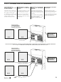
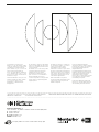
FIG. 2 - CONNECTION OF SPEAKERS
8 Ω
8 Ω
COLLEGAMENTO delle
CASSE ACUSTICHE alle USCITE
dell'AMPLIFICATORE
L’impedenza di carico minima è di
2 ohm. Ciò vi consente di collegare
due o quattro casse da 8 ohm.
La combinazione con quattro casse
da 8 ohm rappresenta la soluzione
ottimale in quanto consente
di sfruttare la massima potenza.
ANSCHLUß der LAUTSPRECHER-
BOXEN an den VERSTARKER-
AUSGANG
Die Mindest-Impedanz beträgt
2 Ohm. Zum Anschließen von z.B
zwei oder vier Lautsprecher-Boxen
an 8-Ohm.
Die Kombination mit vier 8-Ohm
Boxen stellt eine optimale Lösung
dar, da die Leistung des
Verstärkers optimal ausgenützt
wird.
MONITOR AMPLIFICATO
POWERED MONITOR
AKTIV-MONITOR
MONITOR AMPLIFIE'
CASSE ACUSTICHE CONSIGLIATE / SUGGESTED SPEAKER COMBINATIONS / EMPFOHLENE LAUTSPRECHERBOXEN / ENCEINTES CONSEILLEES
2 o / or / oder / ou 4 Montarbo mod. 189S, 299S, 210, 260, T10P, 312, 412, T12P, 315, 415, T15P
CONNECTING the SPEAKER
ENCLOSURES to the AMPLIFIER
OUTPUT
The minumum impedance is 2 ohms.
This allows you to connect two or
four 8-ohms speaker enclosures.
The use of four 8-ohms speakers
represents the optimum solution
as it allows to exploit the maximum
output power.
RACCORDEMENT d’ENCEINTES
ACOUSTIQUES
Impédance minimum 2 ohms.
Ce vous permet de brancher deux
ou quatre enceintes de 8 ohms
La solution optimale (4 enceintes de
8 ohm) permet d’exploiter toute la
puissance de l’amplicateur.
CASSE ACUSTICHE
SPEAKER ENCLOSURES
LAUTSPRECHERBOXEN
ENCEINTES ACOUSTIQUES
CASSE ACUSTICHE
SPEAKER ENCLOSURES
LAUTSPRECHERBOXEN
ENCEINTES ACOUSTIQUES
8 Ω 8 Ω
8 Ω 8 Ω
MONITOR AMPLIFICATO
POWERED MONITOR
AKTIV-MONITOR
MONITOR AMPLIFIE'

458S
10
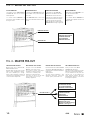
FIG. 3 - MONITOR OUTPUT
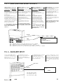
PRISE MASTER PRE-OUT:
Cette prise Jack est la SORTIE
PREAMPLIFIEE du mixeur.
Elle dépend des réglages du volume
Master et de l'égaliseur graphique.
La prise Master Pre-out peut être
utilisée pour le raccordement au
mixer principal, pupitres de régie,
amplicateurs externes ou enceintes
acoustiques ampliées.
MONITOR-AUSGANG
• Verbinden Sie die MONITOR
OUT Buchse des Mixers mit dem
EINGANG des aktiven Monitors.
• Das Monitor-Signal jedes Kanals
kan mit Hilfe des Monitor Reglers
festgelegt werden. Die Gesamt-
stärke des Monitors wird mit dem
MONITOR Master-Regler eingestellt.
oppure / or / oder / ou
oppure / or / oder / ou
MASTER PRE-OUT
CASSE ACUSTICHE
SPEAKER ENCLOSURES
LAUTSPRECHERBOXEN
ENCEINTES ACOUSTIQUES
FINALI DI POTENZA
POWER AMPLIFIERS
ENDSTUFEN
AMPLIFICATEUR
MIXER (ingressi LINEA)
MIXERS (LINE inputs)
MISCHPULTE (LINE-Eingänge)
MIXEUR (entré ligne)
MASTER PRE-OUT BUCHSE
Diese Klinkenbuchse ist der AUSGANG
des Mixers VOR DER ENDSTUFE. Sie
liegt hinter dem Summen-Lautstärke-
Regler und
dem Equalizer.
Sie kann externe Endstufen oder
Aktivboxen ansteuern, sowie auch
ein P.A. System, Studio-Pulte u.s.f.
MASTER PRE-OUT SOCKET
This jack socket is the PREAMP.
OUTPUT of the mixer section
(Post master volume and graphic
equalizer). It may be used for
connection to external power
ampliers, powered speaker
enclosures, as well as to the main
mixer, studio consoles or any
auxiliary equipment.
SORTIE MONITOR
• Raccorder la prise MONITOR à l'en-
trée de l'enceinte monitor
auto-ampliée.
• Le volume master MONITOR est
le mixage des departs monitor de
chaque canal.
USCITA MONITOR
• Collegare la presa MONITOR OUT
all'INGRESSO della cassa monitor
autoamplicata.
• Il controllo master MONITOR è la
miscelazione delle mandate monitor
dei singoli canali.
MONITOR OUTPUT
• Connect the MONITOR OUT socket
to the INPUT of the powered monitor
enclosure.
• The MONITOR master control is the
mix of the individual channel monitor
sends.
PRESA MASTER PRE-OUT
Questa presa jack è l'USCITA PRE-
AMPLIFICATA del mixer.
Dipende dalle regolazioni del volume
master e dell' equalizzatore graco.
Può essere utilizzata per il collega-
mento al mixer principale, a banchi di
regia oppure per amplicatori esterni
o casse acustiche amplicate.
MONITOR OUT
MONITOR VOLUME
MONITOR AMPLIFICATO
POWERED MONITOR
AKTIV-MONITOR
MONITOR AMPLIFIE'
FIG. 4 - MASTER PRE-OUT

458S
11
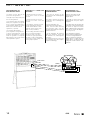
FIG. 5 - SEND & RETURN INSERT SOCKETS
SEND (Pre-Out): This output feeds
the preamplier output signal (post
volume control).
Plugging a jack into this socket, the
power amplier is not disconnected
from the preamplier, this allows to
take the signal out during normal
operation of the amplier.
RETURN (Main-In): It is connected
to the internal power amplier input.
Plugging a jack into this
socket interrupts the internal
connection between preamplier and
amplier.
The preamplier output is still
available at the Pre-out socket.
☞ You mau use these sockets
for connecting an external device
such as Equalizer, effect unit etc..
SEND (Pre-Out): Su questa presa
è presente il segnale di uscita del
preamplicatore, che dipende dal
volume master. Inserendovi una
spina jack, l’amplicatore di potenza
interno resta collegato al preamplica-
tore. Ciò permette di prelevare il segna-
le durante il normale funzionamento
dell’apparecchio.
Return (Main-In): Questa presa
è collegata all’ingresso dell’ampli-
catore di potenza interno.
Inserendo il jack viene interrotto il
collegamento interno tra amplicatore
e preamplicatore. L’uscita del pream-
plicatore continua ad essere
presente sulla presa pre-out.
☞ Potete utilizzare queste prese
per il collegamento di apparecchi
esterni come equalizzatori,
effetti ecc..
SEND (Pre-Out)-Buchse: Hier liegt
das Ausgangs-Signal des
Vorverstärkers an, nach dem Kanal-
Lautstärke-Regler. Durch Einstecken
eines Klinkensteckers entsteht keine
Signal-Unterbrechung.
Dies ermöglicht eine Signal-
Abnahme während des normalen
Betriebes.
RETURN (Main-In)-Buchse:
Diese Buchse liegt direkt am
Eingang der Endstufe. Durch
Einstecken des Klinkensteckers
wird die interne Verbindung
zwischen Endstufe und Summe
unterbrochen. Das Vorverstärker-
Signal liegt jedoch an der Pre-Out-
Buchse an.
☞ An diese Buchsen kann mann
einen externen Gerät
anschließen,wie z.B Equalizer,
Effekt-Gerät u.s.w.
output
input
max. livello ingresso: -10dB
max. input level: -10dB
max. Eingangs-Pegel: -10dB
max. niveau d'entrée: -10dB
output
MIXER
AUX volume
SEND
EQUALIZER,
EXTERNAL EFFECT, etc..
SEND → INGRESSO apparecchio esterno, USCITA apparecchio esterno → RETURN
SEND → INPUT of the external device, OUTPUT the external device → RETURN
SEND → EINGANG des externen Gerätes, AUSGANG des externen Gerätes → RETURN
SEND → ENTREE de l'effet exterieur ou enree ligne du melangeur SORTIE de l'effet extrieur → RETURN
RETURN
SEND (PRE-OUT): sortie jack 0 dB
pour le branchement d’un effet exte-
rieur ou d’un mélangeur.
L’insertion d’un jack dans cette sortie
ne provoque pas de coupure du prem-
pli. Le signal present sur cette
prise est prelevé après tonalité, après
ltre et avant limiteur.
RETURN (MAIN IN): cette prise
est raccordée à la sortie (mixed)
de l’effet exterieur. L’insertion d’un
jack sur cette prise provoque la cou-
pure du preampli.
☞ On peut utiliser les prises Send/
Return pour brancher un effet
exterieur (egaliseur, etc..).
L'ingresso AUSILIARIO permette
il collegamento di qualsiasi tipo di sor-
gente sonora, (es: un mixer ausiliario,
un microfono ecc.. )
avente livello di uscita adeguato.
The AUXILIARY input allows
connection of any sound source,
(such as an auxiliary mixer, a
microphone etc..) having suitable
output level.
Der AUXILIARY-Eingang ermöglicht
den Anschluß aller Arten von
Tonquellen (z.B. den eines Sub-
Mixers, eines Mikrophons etc.) bei
entesprechendem Pegel.
L’entrée AUXILIAIRE (niveau
max.d’entrée: -10 dB), permet le rac-
cordement de n’importe quel genre de
source sonore, comme, par exemple,
un mixeur auxiliaire, un microphone,
etc…, ayant un niveau de sortie
approprié.
AUX IN
FIG. 6 - AUXILIARY INPUT

458S
12
FIG. 7 - TAPE IN / OUT
HOOKING UP A STEREO TAPE
RECORDER.
• Connect the Tape-out sockets
to the Line-in sockets of the tape
recorder.
• Connect the Tape-in sockets to
the Line-out sockets of the tape
recorder.
• For playback, switch the recorder
to play and adjust the Auxiliary
volume and the Master volume
(and the output volumes of the
tape recorder, if available).
• For recording, switch the recorder to
the 'record' mode and adjust
the input volume of the tape
recorder. The signal presented to
the tape recorder is independent
of the master volume setting and
of the graphic equalizer.
ANSCHLUß EINES STEREO
TONBANDGERÄTES
• Die Tape-out Buchsen an die
Line-in Buchsen des Tonbandgerätes
anschließen.
• Die Tape-in -Buchsen an die Line-
out-Buchsen des Tonbandgerätes
anschließen.
• Für die Wiedergabe: der
Tonbandgerät auf 'Wiedergabe'
stellen, sowie die AUX- und Sum-
men-Lautstärke (ggfs. auch die
Ausgangs-Lautstärken des Tonband-
gerätes) aussteuern.
• Für die Aufnahme: das Tonband-
gerät auf 'Aufnahme' stellen und
die VU-Meter des Tonbandgerätes
aussteuern.
Der Aufnahmepegel ist von der Sum-
men-Lautstärke und dem Graphik-
Equalizer unabhängig.
RACCORDEMENT d'un
MAGNETOPHONE STEREO
• Relier les prises Tape-out du
pupitre aux prises Line-in du
magnetophone.
• Raccorder les prises Line-out du
magnetophone aux prises Tape-in
du pupitre.
• Pour Reproduire des cassettes deja
enregistrèes: régler le magnétophone
sur 'lecture' et régler les volumes
'AUX' et Master de façon appropriée
(ainsi que les volumes du magnéto-
phone s’il y a en à).
• Pour Enregistrer a partir du
pupitre: mettre le magnétophone
en fonction d’enregistrement et
régler les volumes de l’entrée du
magnetophone. Le signal envoyé au
magnetophone ne depend pas de
regrages du volume 'master' et de
l'égaliseur.
COLLEGAMENTO DI UN
REGISTRATORE STEREO
• Collegare le prese Tape-out alle
prese Line-in del registratore.
• Collegare le prese Tape-in alle prese
Line-out del registratore.
• Per riprodurre nastri già registrati,
basta porre il registratore in riprodu-
zione e regolare opportunamente il
volume Ausiliario (AUX) ed il volume
Master (ed i volumi di uscita del
registratore, se presenti).
• Per registrare dall’impianto:
porre il registratore in registrazione
e regolare opportunamente i volumi
di ingresso del registratore. Il segnale
inviato al registratore non dipende
dalla regolazione del volume master
e dall’equalizzatore graco.
AUX volume
LINE IN
TAPE OUT
TAPE IN
LINE OUT
TAPE RECORDER

458S
13
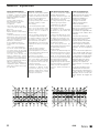
TECHNICAL SPECIFICATIONS
SPECIFICATIONS
• Inputs:
micro 3mV / line 50 mV
• Tone controls:
treble ± 20dB @10kHz
bass ± 20dB @40Hz
• 9-band graphic equalizer:
63-125-250-500-1000-2000-
4000-8000-16000 Hz/ ±12 dB
• T.H.D (mixer): < 0,01%
• Bandwidth (mixer):
20Hz ÷ 20kHz / ±2dB
• Bandwidth (eco):
40Hz ÷ 11kHz
• Signal-to-noise ratio (echo):
>92 dB
• Load protection by means of
delayed relay
• OUTPUT POWER:
350 W rms into 2 ohms
• Dimensions (WxHxD):
closed 46,5 x 40 x 20 cm
open 46,5 x 82 x 38 cm
• Weight: 16kg
TECHNISCHE DATEN:
• Eingänge:
Mikrophon 3 mV / Line 50 mV
• Tonregler:
Höhen ± 20dB bei 10kHz
Bässe ± 20dB bei 40Hz
• 9-Band Graphik-Equalizer
für folgende Frequenezn:
63-125-250-500-1000-2000-
4000-8000-16000Hz / ±12dB
• Klirrfaktor Mischpult: <0,01%
• Frequenzgang (Mixer):
20Hz ÷ 20kHz / ± 2 dB
• Frequenzgang (Echo):
40Hz ÷ 11kHz
• Rauschabstand (Echo):
> 92 dB
• Lautsprecherschutz durch
Verzögerungs-Relais
• AUSGANGSLEISTUNG:
350 W rms an 2 Ohm
• Abmessungen (BxHxT):
offen 46,5x 40x 20 cm
geschlossen 46,5 x 82 x38cm
• Gewicht: 16kg
CARACTERISTIQUES TECHINIQUES
• Entrées:
micro 3mV / line 50mV
• Contrôle de tonalité
aigues ± 20dB @ 10KHz
basses ± 20dB @ 40Hz
• Egaliseur graphique stereo
9 bandes:
63-125-250-500-1000-2000-
4000-8000-16000Hz/12dB
•Distorsion T.H.D.: <0,01%
• Bande passante (mixer):
20Hz ÷ 20KHz / ±2dB
• Bande passante (echo):
40Hz ÷ 11KHz
• Bruit (echo):
<92dB
• Protection du charge par relais
• PUISSANCE DE SORTIE:
350W rms en 2 ohm
• Dimensions (LxHxP):
fermée 46,5 x 40 x 20 cm
ouvert 46,5 x 82 x 38 cm
• Poid: 16Kg
DATI TECNICI
• Ingressi:
micro 3mV / linea 50 mV
• Controlli di tono:
alti ± 20dB @ 10kHz
bassi ± 20dB @ 40Hz
• Equalizzatore graco a 9 bande
centrato sulle seguenti frequenze:
63-125-250-500-1000-2000-
4000-8000-16000 Hz/ ±12 dB
• Distorsione armonica totale (mi-
xer): < 0,01%
• Banda passante (mixer):
20Hz ÷ 20kHz / ±2dB
•B anda passante (eco):
40Hz ÷ 11KHz
• Rapporto segnale/disturbo (eco):
> 92 dB
• Protezione del carico mediante relè
ad inserzione ritardata
• POTENZA DI USCITA:
350 W rms su 2 ohm
• Dimensioni (LxHxP):
chiuso 46,5 x 40 x 20 cm
aperto 46,5 x 82 x 38 cm
• Peso: 16kg
I.E.C. POWER SUPPLY SOCKET (page 5 n. 19)
fuse replacement
always replace with fuse of
the same type and rating
RESERVE FUSE
La pagina si sta caricando...
La pagina si sta caricando...
La pagina si sta caricando...
La pagina si sta caricando...
La pagina si sta caricando...
La pagina si sta caricando...

Le informazioni contenute in questo
manuale sono state attentamente redatte
e controllate. Tuttavia non si assume alcuna
responsabilità per eventuali inesattezze.
Questo manuale non può contenere una
risposta a tutti i singoli problemi che
possono presentarsi durante l'installazione
e l'uso dell'apparecchio. Siamo a vostra
disposizione per fornirvi eventuali ulteriori
informazioni e consigli.
La Elettronica Montarbo srl non può essere
ritenuta responsabile per danni o incidenti
a cose o persone, causati o connessi
all’utilizzazione o malfunzionamento
dell’apparecchio.
The information contained in this manual
has been carefully drawn up and checked.
However no responsibility will be assumed
for any inexactitude.
This manual can not cover all the possible
contingencies which may arise during
installation and use of the product.
Should further information be desired,
please contact us or our local distributor.
Elettronica Montarbo srl can not be
considered responsible for damages which
may be caused to people and things when
using this product.
Les indications contenues en ce manuel ont
été attentivement rédigées et contrôlées.
Toutefois nous n'assumons aucune
responsabilité pour des éventuelles
inexactitudes. Ce manuel ne peut contenir
une réponse pour problèmes particuliers qui
pourraient se présenter lors de l’installation
et de l’usage de l’appareil. Nous sommes à
votre disposition pour d’éventuels conseils
et informations supplémentaires.
Elettronica Montarbo srl ne peut être
consideré responsable des dommages causés
à des personnes ou à des objects lors de
l'utilisation du produit.
Die in dieser Bedienungsanleitung
enthaltenen Hinweise wurden sorgfältig
bearbeitet und korrigiert. Es wird jedoch
keine Gewähr für die Richtigkeit der
Angaben übernommen.
Diese Bedienungsanleitung kann nicht alle
Richtlinien und Probleme berücksichtigen,
welche während der Aufstellung und
Verwendung des Gerätes entstehen
können. Sollten Sie Fragen haben, wenden
Sie sich bitte an uns oder an den für Ihr
Land zuständigen Importeur.
Die Elettronica Montarbo srl haftet nicht,
für Personen- oder Sachschäden die durch
die Verwendung des Gerätes entstehen.
caratteristiche e dati tecnici possono essere modificati senza preavviso. specifications and features are subject to change without prior notice.
änderungen vorbehalten. sous reserve de modifications.
Elettronica Montarbo srl
via G. di Vittorio 13 | 40057 Cadriano Granarolo Emilia (BO) ITALY
T +39 051 6047711
F +39 051 765226
www.montarbo.com
Company under the control of EKO Music Group SpA
-
 1
1
-
 2
2
-
 3
3
-
 4
4
-
 5
5
-
 6
6
-
 7
7
-
 8
8
-
 9
9
-
 10
10
-
 11
11
-
 12
12
-
 13
13
-
 14
14
-
 15
15
-
 16
16
-
 17
17
-
 18
18
-
 19
19
-
 20
20


Montarbo 458S Manuale del proprietario
- Categoria
- Altoparlanti
- Tipo
- Manuale del proprietario
in altre lingue
- English: Montarbo 458S Owner's manual
- français: Montarbo 458S Le manuel du propriétaire
- Deutsch: Montarbo 458S Bedienungsanleitung