
1
4 5 6 7 8
2
1
6 7 8 9
10 11
2 1 2 3 4 5
3
1
4 5 6 7 8
2
1
6 7 8 9
10 11
2 1 2 3 4 5
3
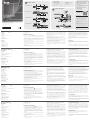
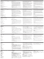
Hardware Review
A
Front View
1. Power LEDs
2. Port LEDs
3. LAN LEDs
4. Laptop USB Console Port
5. USB Ports
6. Reset Switch
7. Audio Ports
8. Port Switching Buttons
Rear View
1. Power Sockets
2. Power Switches
3. PON Port
4. Serial 2 Port (Secondary)
5. LAN2 Port (Secondary)
6. Grounding Terminal
7. Modem Port
8. Serial 1 Port (Primary)
9. LAN1 Port (Primary)
10. Local Console Ports
11. KVM Ports
Hardware Installation
B
1. Plug your Local Console’s keyboard, monitor, and mouse in to the unit’s
Console Ports. Each port is color coded and marked with an appropriate
icon.
2. If you are using a laptop to control the KN1108VA / KN1116VA locally,
use the Laptop USB Console Cable included in the package to connect
the laptop to the KN1108VA / KN1116VA's Laptop USB Console port,
located on the unit's front panel.
3. Use Cat 5e cable to connect any available KVM port to a KVM Adapter
Cable.
4. Connect KVM Adapter to server.
5. Plug a cable from the LAN or WAN into the KN1108VA / KN1116VA's
LAN1 Port.
6. (Optional) Plug another cable from the LAN or WAN into the KN1108VA
/ KN1116VA's LAN2 Port.
7. (Optional) Use Cat 5e cable to connect the KN1108VA / KN1116VA
PON port to an SA0142 Adapter. Connect the Adapter to the PON IN
port of a PDU unit.
8. (Optional) Use Cat 5e cable to connect the KN1108VA / KN1116VA’s
Modem port to an SA0142 Adapter. Then connect SA0142 Adapter to
the modem’s DB-9 port.
9. (Optional) For serial connectivity, use Cat 5e cable to connect the
KN1108VA / KN1116VA’s Serial 1 port to an SA0142 Adapter. Then
connect SA0142 Adapter to the serial device.
10. (Optional) For further serial connectivity, use Cat 5e cable to connect
the KN1108VA / KN1116VA’s Serial 2 Port to an SA0142 Adapter.
Connect SA0142 Adapter to the serial device.
11. Ground the switch. Use the grounding wire to connect the switch’s
grounding terminal to a suitable grounded object.
12. Plug the power cord. After the KN1108VA / KN1116VA installation,
you can turn on the power. After it is powered on, you can turn on
the servers.
Administrator Setup
When the local console has been connected up and the KN1108VA
/ KN1116VA is on, a login prompt appears on the console monitor.
Since this is the fi rst time you are logging in, use the default Username:
administrator; and the default Password: password. For security purposes,
use the User Management function to change these to a unique
Username and Password.
Then, select Device Management > Network to set up the switch for
network operation. To add users, select User Management > Users, then
click Add.
Operation
KVM over IP switches can be accessed from a local console; an internet
browser; a Windows application (AP) program; and a Java application (AP)
program.
After you have successfully logged in, the Port Access page comes up with
the KVM over IP switch’s KVM Connections page displayed for operation.
B
Package Contents
1 KN1108VA / KN1116VA 8/16-Port
KVM over IP Switch
2 SA0142 Serial Adapters
(RJ45-F to DB9-M; DTE to DCE)
2 Power Cords
Hardware Installation
© Copyright 2017 ATEN
®
International Co., Ltd.
ATEN and the ATEN logo are trademarks of ATEN International Co., Ltd. All rights reserved. All
other trademarks are the property of their respective owners.
This product is RoHS compliant.
Part No. PAPE-1223-G80G Printing Date:11/2017
8/16-Port KVM over IP Switch
Quick Start Guide
KN1108VA / KN1116VA
KN1108VA / KN1116VA 8/16-Port KVM over IP Switch
www.aten.com
Commutateur KVM sur IP 8/16 ports KN1108VA / KN1116VA
www.aten.com
KN1108VA / KN1116VA – 8/16-Port-KVM-over-IP-Switch
www.aten.com
Conmutador de 8/16 puertos KVM sobre IP KN1108VA / KN1116VA
www.aten.com
Switch KVM over IP KN1108VA / KN1116VA a 8/16 porte
www.aten.com
ATEN Altusen
™
KN1108VA Front View
KN1108VA Rear View
KN1116VA Front View
KN1116VA Rear View
1 Laptop USB Console Cable
1 Mounting Kit
1 Foot Pad Set (4 pcs.)
1 User Instructions
Support and Documentation Notice
All information, documentation, fi rmware,
software utilities, and specifi cations
contained in this package are subject to
change without prior notifi cation by
the manufacturer.
To reduce the environmental impact of our
products, ATEN documentation and software
can be found online at
http://www.aten.com/download/
Technical Support
www.aten.com/support
이 기기는 업무용(A급) 전자파적합기기로서 판매자 또는
사용자는 이 점을 주의하시기 바라며, 가정외의 지역에
서 사용하는 것을 목적으로 합니다.
EMC Information
FEDERAL COMMUNICATIONS COMMISSION INTERFERENCE
STATEMENT:
This equipment has been tested and found to comply with the limits
for a Class A digital device, pursuant to Part 15 of the FCC Rules.
These limits are designed to provide reasonable protection against
harmful interference when the equipment is operated in a commercial
environment. This equipment generates, uses, and can radiate radio
frequency energy and, if not installed and used in accordance with
the instruction manual, may cause harmful interference to radio
communications. Operation of this equipment in a residential area
is likely to cause harmful interference in which case the user will be
required to correct the interference at his own expense.
FCC Caution: Any changes or modifi cations not expressly approved by
the party responsible for compliance could void the user's authority to
operate this equipment.
Warning: Operation of this equipment in a residential environment
could cause radio interference.
Warning: This equipment is compliant with Class A of CISPR 32. In a
residential environment this equipment may cause radio interference.
Suggestion: Shielded twisted pair (STP) cables must be used with the
unit to ensure compliance with FCC & CE standards.
This device complies with Part 15 of the FCC Rules. Operation is subject
to the following two conditions:(1) this device mat not cause harmful
interference, and(2) this device must accept any interference received,
including interference that may cause undesired operation.
Scan for
more information
4
12
11
4
3
5
9
6
10
7
8
1
PDU
Modem
2
Présentation du matériel
A
Vue de devant
1. LED d'alimentation
2. LED de port
3. LED LAN
4. Port Console USB Ordinateur portable
5. Ports USB
6. Bouton de réinitialisation
7. Ports audio
8. Boutons de commutation de ports
Vue de derrière
1. Prises d'alimentation
2. Boutons d'alimentation
3. Port PON
4. Port série 2 (secondaire)
5. Port LAN2 (Secondaire)
6. Borne de terre
7. Port modem
8. Port série 1 (primaire)
9. Port LAN1 (Primaire)
10. Ports Console locale
11. Ports KVM
Installation du matériel
B
1. Branchez le clavier, le moniteur et la souris de votre console locale sur
les ports console de l'appareil. Chaque port est codé par couleur et
étiqueté avec une icône appropriée.
2. Si vous utilisez un ordinateur portable pour contrôler le KN1108VA /
KN1116VA localement, utilisez le câble console USB de l’ordinateur
portable fourni dans l’emballage pour connecter l’ordinateur portable
au port console USB Ordinateur portable du KN1108VA / KN1116VA,
situé en face avant de l’appareil.
3. Utilisez un câble Cat 5e pour raccorder un port KVM disponible à un
câble adaptateur KVM.
4. Connectez l’adaptateur KVM au serveur.
5. Branchez un câble depuis le LAN ou le WAN vers le port LAN1 du
KN1108VA / KN1116VA.
6. (Facultatif) Branchez un autre câble depuis le LAN ou le WAN vers le
port LAN2 du KN1108VA / KN1116VA.
7. (Facultatif) Utilisez un câble Cat 5e pour raccorder le port PON
du KN1108VA / KN1116VA à un adaptateur SA0142. Connectez
l’adaptateur au port d’entrée PON d'une unité PDU.
8. (Facultatif) Utilisez un câble Cat 5e pour raccorder le port Modem du
KN1108VA / KN1116VA à un adaptateur SA0142. Connectez ensuite
l’adaptateur SA0142 au port DB-9 du modem.
9. (Facultatif) Pour la connectivité série, utilisez un câble Cat 5e afi n de
raccorder le port série 1 du KN1108VA / KN1116VA à un adaptateur
SA0142. Puis raccordez l’adaptateur SA0142 au périphérique série.
10. (Facultatif) Pour plus de connectivité série, utilisez un câble Cat 5e
afi n de raccorder le port série 2 du KN1108VA / KN1116VA à un
adaptateur SA0142. Raccordez l’adaptateur SA0142 au périphérique
série.
11. Reliez le commutateur à la terre. Utilisez le fi l de mise à la terre pour
raccorder la borne de mise à la terre du commutateur à un objet relié
à une terre appropriée.
12. Branchez le cordon d'alimentation. Après l’installation du
KN1108VA / KN1116VA, vous pouvez mettre sous tension. Après la
mise sous tension, vous pouvez allumer les serveurs.
Confi guration administrateur
Lorsque la console locale a été connectée et le KN1108VA / KN1116VA
allumé, une invite de connexion apparait sur le moniteur de la console.
Comme il s’agit de la première fois que vous vous connectez, utilisez
l’identifi ant par défaut : administrator; et le mot de passe par défaut :
password. Pour des raisons de sécurité, utilisez la fonction de gestion des
utilisateurs pour les changer au profi t d’un identifi ant et d'un mot de
passe uniques.
Ensuite, sélection Gestion appareil > Réseau pour confi gurer le
commutateur pour un fonctionnement en réseau. Pour ajouter des
utilisateurs, sélectionnez Gestion utilisateurs > Utilisateurs, puis cliquez sur
Ajouter.
Fonctionnement
Les commutateurs KVM sur IP sont accessibles depuis une console locale;
un navigateur Internet; un programme d’application Windows (AP); et un
programme d’application Java (AP).
Après vous être connecté avec succès, la page d’accès aux ports s’affi che
avec la page des connexions KVM du commutateur KVM sur IP à l’écran
pour l’utilisation.
Hardwareübersicht
A
Ansicht von vorne
1. Betriebsanzeige-LED
2. Anschluss-LEDs
3. LAN-LEDs
4. Laptop-USB-Console-Port
5. USB-Ports
6. Reset-Schalter
7. Audioanschlüsse
8. Portwechseltasten
Ansicht von hinten
1. Netzanschlüsse
2. Ein-/Ausschalter
3. PON-Port
4. Seriell-2-Port (sekundär)
5. LAN-2-Port (sekundär)
6. Erdungsklemme
7. Modemanschluss
8. Seriell-1-Port (primär)
9. LAN-1-Port (primär)
10. Lokale Konsolenanschlüsse
11. KVM-Ports
Hardwareinstallation
B
1. Schließen Sie Tastatur, Monitor und Maus Ihrer lokalen Konsole an die
Konsolenanschlüsse des Gerätes an. Jeder Anschluss ist farbig codiert
und mit einem geeigneten Symbol gekennzeichnet.
2. Wenn Sie den KN1108VA / KN1116VA lokal mit einem Notebook
steuern, verbinden Sie das Notebook mit dem mitgelieferten Laptop-
USB-Console-Kabel mit dem Laptop-USB-Console-Anschluss des
KN1108VA / KN1116VA an der Frontblende des Gerätes.
3. Verbinden Sie jeden verfügbaren KVM-Port über ein Cat-5e-Kabel mit
einem KVM-Adapterkabel.
4. Verbinden Sie den KVM-Adapter mit dem Server.
5. Schließen Sie ein Kabel vom LAN oder WAN an den LAN-1-Port des
KN1108VA / KN1116VA an.
6. (Optional) Schließen Sie ein weiteres Kabel vom LAN oder WAN an den
LAN-2-Port des KN1108VA / KN1116VA an.
7. (Optional) Verbinden Sie den PON-Anschluss des KN1108VA /
KN1116VA über ein Cat-5e-Kabel mit einem SA0142-Adapter.
Verbinden Sie den Adapter mit dem PON-Eingang der PDU.
8. (Optional) Verbinden Sie den Modemanschluss des KN1108VA /
KN1116VA über ein Cat-5e-Kabel mit einem SA0142-Adapter.
Verbinden Sie den SA0142-Adapter dann mit dem DB-9-Port des
Modems.
9. (Optional) Verbinden Sie den Seriell-1-Port des KN1108VA / KN1116VA
über ein Cat-5e-Kabel für serielle Konnektivität mit einem SA0142-
Adapter. Verbinden Sie den SA0142-Adapter dann mit dem seriellen
Gerät.
10. (Optional) Verbinden Sie den Seriell-2-Port des KN1108VA /
KN1116VA über ein Cat-5e-Kabel für weitere serielle Konnektivität mit
einem SA0142-Adapter. Verbinden Sie den SA0142-Adapter mit dem
seriellen Gerät.
11. Erden Sie den Switch. Verbinden Sie die Erdungsklemme des Switch
über ein Erdungskabel mit einem geeigneten geerdeten Objekt.
12. Schließen Sie das Netzkabel an. Nach Installation des KN1108VA /
KN1116VA können Sie ihn einschalten. Sobald er hochgefahren ist,
können Sie die Server einschalten.
Administratoreinrichtung
Wenn die lokale Konsole verbunden wurde und der KN1108VA /
KN1116VA eingeschaltet ist, erscheint eine Anmeldeaufforderung am
Konsolenmonitor. Verwenden Sie bei erstmaliger Anmeldung den Stand
ardbenutzernamen:administrator; und das Standardkennwort:password.
Richten Sie aus Sicherheitsgründen mit der Nutzerverwaltung-Funktion
einen eindeutigen Nutzernamen und ein Kennwort ein.
Wählen Sie dann Geräteverwaltung > Netzwerk und stellen Sie den
Switch auf Netzwerkbetrieb ein. Wählen Sie zum Zufügen von Nutzern
Nutzerverwaltung > Nutzer, klicken Sie dann auf Zufügen.
Bedienung
KVM-over-IP-Switches sind über eine lokale Konsole; einen
Internetbrowser; eine Windows-Anwendung und eine Java-Anwendung
zugänglich.
Nach erfolgreicher Anmeldung erscheint die Portzugang-Seite mit der
KVM-Verbindungen-Seite des KVM-over-IP-Switch.
Revisión del hardware
A
Vista frontal
1. LED de alimentación
2. LEDs de puerto
3. LEDs de LAN
4. Puerto USB de consola para equipo portátil
5. Puertos USB
6. Botón de reinicio
7. Puertos de audio
8. Botones para cambiar de puerto
Vista posterior
1. Tomas de corriente
2. Interruptores de alimentación
3. Puerto PON
4. Puerto serie 2 (Secundario)
5. Puerto LAN2 (Secundario)
6. Terminal de toma de tierra
7. Puerto módem
8. Puerto serie 1 (Primario)
9. Puerto LAN1 (Primario)
10. Puertos consola local
11. Puertos KVM
Instalación del hardware
B
1. Conecte el teclado, el monitor y el ratón de la consola local a los
puertos de la unidad de consola. Cada puerto está codifi cado por
colores y marcado con un icono apropiado.
2. Si utiliza un PC portátil para controlar localmente el KN1108VA /
KN1116VA, utilice el cable de consola portátil USB incluido en el
paquete para conectar el PC portátil al puerto de consola portátil USB
KN1108VA / KN1116VA situado en el panel frontal de la unidad.
3. Utilice el cable Cat 5e para conectar cualquier puerto KVM disponible a
un cable adaptador KVM.
4. Conecte el adaptador KVM al servidor.
5. Conecte un cable desde la LAN o WAN en el puerto LAN1 del
KN1108VA / KN1116VA.
6. (Opcional) Conecte otro cable desde la LAN o WAN al Puerto LAN2 del
KN1108VA / KN1116VA.
7. (Opcional) Utilice el cable Cat 5e para conectar el puerto PON
KN1108VA / KN1116VA a un adaptador SA0142. Conecte el adaptador
al puerto de ENTRADA PON de una unidad PDU.
8. (Opcional) Utilice el cable Cat 5e para conectar el puerto de módem
KN1108VA / KN1116VA a un adaptador SA0142. A continuación,
conecte el adaptador SA0142 al puerto DB-9 del módem.
9. (Opcional) Para la conectividad en serie, utilice el cable Cat 5e para
conectar el puerto serie 1 del KN1108VA / KN1116VA a un adaptador
SA0142. A continuación, conecte el adaptador SA0142 al dispositivo
serie.
10. (Opcional) Para una mayor conectividad en serie, utilice el cable Cat
5e para conectar el puerto serie 2 del KN1108VA / KN1116VA a un
adaptador SA0142. Conecte el adaptador SA0142 al dispositivo serie.
11. Conecte el interruptor a tierra. Utilice el cable de conexión a tierra
para conectar el terminal de conexión a tierra del conmutador a un
objeto conectado a tierra adecuadamente.
12. Conecte el cable de alimentación. Después de la instalación del
KN1108VA / KN1116VA, puede conectar la alimentación. Una vez
encendido, puede encender los servidores.
Confi guración del administrador
Cuando la consola local está conectada y el KN1108VA / KN1116VA
está encendido, aparece un mensaje de inicio de sesión en el monitor
de la consola. Puesto que es la primera vez que inicia sesión, utilice
el nombre de usuario predeterminado: administrator; Y la contraseña
predeterminada: password. Por motivos de seguridad, utilice la función
gestión de usuarios para cambiarlos a un nombre de usuario y contraseña
únicos.
A continuación, seleccione Administrador de dispositivos > Red para
confi gurar el conmutador para el funcionamiento en red. Para agregar
usuarios, seleccione Gestión de usuarios > Usuarios y, a continuación,
haga clic en Agregar.
Funcionamiento
Los conmutadores KVM sobre IP se pueden acceder desde una consola
local; Un navegador de Internet; Un programa de aplicación de Windows
(PA); Y un programa de aplicación Java (PA).
Después de haber iniciado sesión correctamente, la página de Acceso a los
puertos aparece con la página de conexiones KVM del conmutador KVM
sobre IP mostrada para su funcionamiento.
Descrizione hardware
A
Vista anteriore
1. LED alimentazione
2. LED porta
3. LED LAN
4. Porta LUC (Laptop USB Console)
5. Porte USB
6. Interruttore di ripristino
7. Porte audio
8. Tasti di commutazione porta
Vista posteriore
1. Prese di corrente
2. Interruttori di alimentazione
3. Porta PON
4. Porta seriale 2 (secondaria)
5. Porta LAN2 (secondaria)
6. Terminale di massa
7. Porta modem
8. Porta seriale 1 (principale)
9. Porta LAN1 (secondaria)
10. Porte Console locale
11. Porte KVM
Installazione dell'hardware
B
1. Collegare la tastiera della Console locale, il monitor e il mouse alle
porte Console dell'unità. Ciascuna porta è codifi cata con un colore ed è
contrassegnata con una icona appropriata.
2. Se si utilizza un notebook per controllare localmente KN1108VA /
KN1116VA, utilizzare il cavo LUC (Laptop USB Console) presente
nella confezione per collegare il notebook alla porta LUC (Laptop USB
Console) di KN1108VA / KN1116VA, situata sul pannello anteriore
dell'unità.
3. Utilizzare un cavo Cat 5e per collegare qualsiasi porta KVM disponibile
a un cavo adattatore KVM.
4. Collegare l'adattore KVM al server.
5. Collegare un cavo dalla LAN o WAN alla porta LAN1 di KN1108VA /
KN1116VA.
6. (Opzionale) Collegare un altro cavo dalla LAN o WAN alla porta LAN2 di
KN1108VA / KN1116VA.
7. (Opzionale) Utilizzare il cavo Cat 5e per collegare la porta PON
di KN1108VA / KN1116VA ad un adattatore SA0142. Collegare
l'adattatore alla porta PON IN di una unità PDU.
8. (Opzionale) Utilizzare il cavo Cat 5e per collegare la porta Modem di
KN1108VA / KN1116VA ad un adattatore SA0142. Quindi collegare
l'adattatore SA0142 alla porta DB-9 del modem.
9. (Opzionale) Per la connettività seriale, utilizzare il cavo Cat 5e per
collegare la porta seriale 1 di KN1108VA / KN1116VA ad un adattatore
SA0142. Quindi collegare l'adattatore SA0142 al dispositivo seriale.
10. (Opzionale) Per una ulteriore connettività seriale, utilizzare il cavo
Cat 5e per collegare la porta seriale 2 di KN1108VA / KN1116VA ad
un adattatore SA0142. Collegare l'adattatore SA0142 al dispositivo
seriale.
11. Collegare a massa l'interruttore. Utilizzare il cavo di messa a terra per
collegare il terminale di messa a terra dello switch ad un appropriato
elemento di messa a terra.
12. Collegare il cavo di alimentazione. Dopo l'installazione di KN1108VA /
KN1116VA, è possibile accendere l'alimentazione. Dopo l’accensione
è possibile accendere i server.
Confi gurazione amministratore
Una volta collegata la console locale e acceso KN1108VA / KN1116VA, sul
monitor della console viene visualizzata una richiesta di login. Poiché si
tratta del primo login, utilizzare il nome utente predefi nito: amministratore
e la password predefi nita: password. Per motivi di sicurezza, utilizzare la
funzione Gestione utenti per passare a nome utente e password univoci.
Quindi selezionare Gestione utenti > Rete per confi gurare lo switch per
l'operazione di rete. Per aggiungere utenti, selezionare Gestione utenti >
Utenti, quindi fare clic su Aggiungi.
Funzionamento
È possibile accedere agli switch KVM over IP da una console locale,
un browser Internet, un programma applicativo di Windows (AP) e un
programma applicativo di Java (AP).
Dopo aver effettuato l'accesso corretto, appare la pagina Accesso porta
con la pagina Connessioni KVM dello switch KVM over IP visualizzato per
il funzionamento.
A
Hardware Review
La pagina si sta caricando...
-
 1
1
-
 2
2


ATEN KN1108VA Guida Rapida
- Tipo
- Guida Rapida
- Questo manuale è adatto anche per
in altre lingue
- English: ATEN KN1108VA Quick start guide
- français: ATEN KN1108VA Guide de démarrage rapide
- español: ATEN KN1108VA Guía de inicio rápido
- Deutsch: ATEN KN1108VA Schnellstartanleitung
- русский: ATEN KN1108VA Инструкция по началу работы
- português: ATEN KN1108VA Guia rápido
- 日本語: ATEN KN1108VA クイックスタートガイド