
B
Hardware Installation
© Copyright 2019 ATEN
®
International Co., Ltd.
ATEN and the ATEN logo are trademarks of ATEN International Co., Ltd. All rights reserved.
All other trademarks are the property of their respective owners.
Part No. PAPE-1223-S20G Printing Date: 08/2019
1-Local/Remote Share Access Single Port
DVI KVM over IP Switch
Quick Start Guide
CN9600
www.aten.com
www.aten.com
www.aten.com
www.aten.com
www.aten.com
www.aten.com
Package Contents
1 CN9600 DVI KVM over IP Switch
1 KVM Cable (DVI-D, USB, Audio; 1.8m/6ft)
1 USB Cable (1.8 m/6 ft)
1 Power Adapter
1 Mounting Kit
1 User Instructions
A
Hardware Review
Support and Documentation Notice
All information, documentation, fi rmware,
software utilities, and specifi cations contained in
this package are subject to change without prior
notifi cation by the manufacturer.
To reduce the environmental impact of our
products, ATEN documentation and software can
be found online at
http://www.aten.com/download/
Technical Support
www.aten.com/support
이 기기는 업무용(A급) 전자파적합기기로서 판매자 또는 사용자는 이 점을
주의하시기 바라며, 가정외의 지역에서 사용하는 것을 목적으로 합니다.
Scan for
more information
EMC Information
FEDERAL COMMUNICATIONS COMMISSION INTERFERENCE
STATEMENT:
This equipment has been tested and found to comply with the limits
for a Class A digital device, pursuant to Part 15 of the FCC Rules.
These limits are designed to provide reasonable protection against
harmful interference when the equipment is operated in a commercial
environment. This equipment generates, uses, and can radiate radio
frequency energy and, if not installed and used in accordance with
the instruction manual, may cause harmful interference to radio
communications. Operation of this equipment in a residential area
is likely to cause harmful interference in which case the user will be
required to correct the interference at his own expense.
FCC Caution: Any changes or modifi cations not expressly approved by
the party responsible for compliance could void the user's authority to
operate this equipment.
Warning: Operation of this equipment in a residential environment
could cause radio interference.
This device complies with Part 15 of the FCC Rules. Operation is subject
to the following two conditions:(1) this device mat not cause harmful
interference, and(2) this device must accept any interference received,
including interference that may cause undesired operation.
Important. Before proceeding, download the Installation and
Operation Manual by visiting the website, www.aten.com and
navigating to the product page. The manual includes important
warnings, loading specifi cations and grounding instructions.
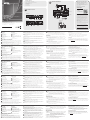
Front View
Rear View
1 2 3 4 5 6 7
1 2 3 4 5
10 9
Front View
Rear View
Network
7 8
1
2
6 5 2
3
2
USB KVM Cable
Connection
4
A
Hardware Review
Front View
1
PC/KVM Port
2
RS-232 DTE Port
3
RS-232 DCE Port
4
USB Type-B Port
5
Virtual Media Port/Laptop USB
Console (LUC) Port
6
Reset Button
7
Power LED
Rear View
1
Grounding Terminal
2
Power Jacks
3
LAN Ports
4
Control Port (connects only to an
optional access control box “2XRT-
0015G” that requires a separate
purchase)
5
Local Console Ports
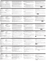
B
Hardware Installation
To install the switch, refer to the installation diagram and perform the following
steps:
1
Plug your USB keyboard, mouse, DVI monitor, speakers and microphone into
the Local Console Ports located on the rear panel.
2
Use the KVM Cable provided with this package to connect the CN9600’s PC/
KVM Port and USB Type-B Port, to the keyboard, mouse, video, speakers and
microphone ports of the server or KVM switch that you are installing.
3
(Optional) If you want to use the virtual media function, use the USB 2.0
Cable provided with this package to connect a USB port on the server to the
CN9600’s Virtual Media Port.
4
(Optional) If you want to use a Laptop USB Console, connect the laptop’s
USB to this LUC Port.
You can switch between the Virtual Media mode and LUC mode through the
OSD settings.
5
(Optional) If you are using other serial devices (data terminal equipment),
such as a touch panel, connect it to the RS-232 DCE Port with a network
switch console cable.
6
(Optional) If you are using other serial devices (data communication
equipment), such as a PC, connect it to the RS-232 DTE Port with a network
switch console cable.
7
Plug a network cable into the CN9600’s LAN Port 1.
8
(Optional) Plug a second network cable into the CN9600’s LAN Port 2.
Note: Dual LAN operation is optional.
9
Plug the power adapter provided with this package into an AC power source,
then plug the power adapter cable into one of the CN9600’s Power Jacks.
Now the CN9600 is turned on.
10
(Optional) Plug the other power adapter into an AC power source, then plug
the power cable into the other CN9600’s Power Jack.
Note: Dual power operation is optional – the second power source is for
back-up; a second power adapter requires a separate purchase.
For safety reasons, we suggest you ground the switch using a grounding wire.
Operation
1. Open your browser and specify the IP address of the CN9600 you want to
access in the browser’s URL location bar.
Note: You can get the IP address from the CN9600 administrator, or see the
“IP Address Determination” section of the user manual. (Default IP
Address: 192.168.0.60)
2. If a Security Alert dialog box appears, accept the certifi cate – it can be trusted.
The Login page appears.
3. Provide a valid Username and Password.
Note: If you are logging in for the fi rst time, use the default Username:
administrator; and the default Password: password.
4. Then click Login to bring up the browser Main Page.
Local IP Setup
Use the local console to set the IP address. All procedures start from the OSD
Main Screen.
1. To pop up the Main Screen, tap [Scroll Lock] twice.
2. When the login screen appears, enter a valid Username and Password to
continue.
Note: If you are logging in for the fi rst time, use the default Username:
administrator; and the default Password: password.
IP Installer
For computers running Windows, an IP address can be assigned with the IP
Installer utility: The utility can be obtained from the Download area of our
website www.aten.com., after downloading the utility to your client computer,
go to the directory that the IP Installer program resides in, and run IPInstaller.
exe.
CN9600 1-Local/Remote Share Access Single Port DVI KVM over IP Switch
A
Description de l’appareil
Vue de face
1
Port PC/KVM (ordinateur/clavier-
écran-souris)
2
Port ETTD RS-232
3
Port ETCD RS-232
4
Port USB Type-B
5
Port de média virtuel / port de console
USB pour ordinateur portable (LUC)
6
Bouton de réinitialisation
7
Voyant d’alimentation
Vue de dos
1
Prise terre
2
Prises d’alimentation
3
Ports LAN
4
Port de contrôle (à ne connecter
qu’à un boîtier de contrôle optionnel
« 2XRT-0015G » qui doit être acheté
séparément)
5
Ports de console locale
B
Installation matérielle
Pour installer le commutateur, reportez-vous au schéma d’installation et effectuez
les opérations suivantes :
1
Branchez votre clavier et souris USB, votre moniteur DVI, vos haut-parleurs et
votre microphone dans les ports de console locale situés sur le panneau arrière.
2
Utilisez le câble KVM fourni avec cet appareil pour brancher le port PC/KVM du
commutateur CN9600 et le port USB Type-B aux ports clavier, souris, vidéo, haut-
parleurs et microphone du serveur ou du commutateur KVM que vous installez.
3
(Facultatif) Si vous souhaitez utiliser la fonction de support virtuel, utilisez le
câble USB 2.0 fourni avec cet appareil pour connecter un port USB du serveur
au port pour support virtuel du commutateur CN9600.
4
(Facultatif) Si vous souhaitez utiliser une console USB pour ordinateur
portable, connectez le port USB de l’ordinateur portable à ce port.
Vous pouvez basculer entre le mode support virtuel et le mode console par le
biais des paramètres du menu de l’affi chage à l’écran.
5
(Facultatif) Si vous utilisez d’autres périphériques série (équipement terminal
de données), par ex. un panneau tactile, connectez-le au port ETCD RS-232 à
l’aide d’un câble de console de commutateur réseau.
6
(Facultatif) Si vous utilisez d’autres périphériques série (équipement de
transmission de données), par ex. un ordinateur, connectez-le au port ETTD
RS-232 à l’aide d’un câble de console de commutateur réseau.
7
Branchez un câble réseau dans le port LAN 1 du commutateur CN9600.
8
(Facultatif) Branchez un second câble réseau dans le port LAN 2 du
commutateur CN9600.
Remarque : l’utilisation du mode double LAN est facultative.
9
Branchez l’adaptateur d’alimentation fourni avec cet appareil à une
prise d’alimentation secteur, puis branchez le câble de l’adaptateur
d’alimentation à l’une des prises d’alimentation du commutateur CN9600. Le
commutateur CN9600 est désormais alimenté.
10
(Facultatif) Branchez l’autre adaptateur d’alimentation à une prise
d’alimentation secteur, puis branchez le câble d’alimentation à l’autre prise
d’alimentation du commutateur CN9600.
Remarque : l’utilisation du mode double alimentation est facultative. La seconde
source d’alimentation sert d’alimentation de secours. Le second
adaptateur d’alimentation secteur doit être acheté séparément.
Pour des raisons de sécurité, nous vous suggérons de mettre le commutateur à la
terre à l’aide d’un fi l de terre.
Fonctionnement
1. Ouvrez votre navigateur et saisissez l’adresse IP du commutateur CN9600
auquel vous voulez accéder dans la barre d’adresse URL du navigateur.
Remarque : vous pouvez obtenir l’adresse IP auprès de l’administrateur
du commutateur CN9600 ou vous reporter au paragraphe
« Détermination de l’adresse IP » du manuel d’utilisation
(l’adresse IP par défaut est : 192.168.0.60).
2. Si une boîte de dialogue d’alerte de sécurité apparaît, acceptez le certifi cat
auquel vous pouvez vous fi er. La page de connexion s’affi che.
3. Renseignez un nom d’utilisateur et un mot de passe valides.
Remarque : si vous vous connectez pour la première fois, utilisez le nom d’utilisateur
par défaut « administrator » et le mot de passe par défaut « password ».
4. Ensuite, cliquez sur la commande de connexion pour accéder à la page
principale dans le navigateur.
Confi guration de l’adresse IP locale
Utilisez la console locale pour défi nir l’adresse IP. Toutes les procédures
s’effectuent à partir de l’écran principal qui s’affi che.
1. Pour affi cher l’écran principal, appuyez deux fois sur la touche [Arrêt défi l].
2. Une fois que l’écran de connexion s’affi che, saisissez un nom d’utilisateur et
un mot de passe valides pour continuer.
Remarque : si vous vous connectez pour la première fois, utilisez le nom
d’utilisateur par défaut « administrator » et le mot de passe par
défaut « password ».
Utilitaire IP Installer
Pour les ordinateurs fonctionnant sous Windows, une adresse IP peut être
attribuée en utilisant l’utilitaire IP Installer. L’utilitaire peut être téléchargé à partir
de l’espace de téléchargement de notre site Internet www.aten.com. Après
avoir téléchargé l’utilitaire sur votre ordinateur client, accédez au dossier où le
programme « IP Installer » se trouve et exécutez le fi chier IPInstaller.exe.
Commutateur sur IP KVM monoport DVI à 1 accès partagé local/distant CN9600
A
Hardwareübersicht
Ansicht von vorn
1
PC/KVM-Port
2
RS-232 DTE-Port
3
RS-232 DCE-Port
4
USB-Typ-B-Port
5
Virtuelle-Medien-Port/Laptop-USB-
Konsolen-Port (LUC-Port)
6
Rücksetztaste
7
Betriebszustands-LED
Ansicht von hinten
1
Erdungsklemme
2
Netzadapteranschlussbuchsen
3
LAN-Ports
4
Steuer-Port (nur für den Anschluss an
die optionale, als Zubehör erhältliche
Zugriffssteuerbox „2XRT-0015G“)
5
Lokale Konsolenports
B
Installation der Hardware
Sehen Sie sich für die Switch-Installation die Abbildung zur Installation an und
führen Sie die nachstehenden Schritte aus:
1
Verbinden Sie Ihre USB-Tastatur, Maus, Lautsprecher sowie Ihren DVI-Monitor
und Ihr Mikrofon mit den lokalen Konsolenports auf der Rückseite.
2
Verbinden Sie den PC/KVM-Port und den USB-Typ-B-Port des CN9600 mit
Hilfe des im Lieferumfang enthaltenen KVM-Kabels mit dem Tastatur-, Maus-,
Video-, Lautsprecher- und Mikrofonport des Servers oder des KVM-Switches,
den Sie gerade installieren.
3
(Optional) Wenn Sie die virtuelle Medienfunktion benutzen möchten, dann
verbinden Sie einen USB-Port des Servers mit Hilfe des im Lieferumfang
enthaltenen USB 2.0-Kabels mit dem virtuellen Medienport des CN9600.
4
(Optional) Wenn Sie eine USB-Laptopkonsole benutzen möchten, dann
verbinden Sie einen USB-Port des Laptops mit diesem LUC-Port.
Sie können über die OSD-Einstellungen zwischen dem virtuellen
Medienmodus und dem LUC-Modus umschalten.
5
(Optional) Wenn Sie andere serielle Geräte (Datenendeinrichtungen) wie
beispielsweise ein Touchpanel benutzen, dann schließen Sie sie mit Hilfe
eines Netzwerk-Switch-Konsolenkabels am RS-232 DCE-Port an.
6
(Optional) Wenn Sie andere serielle Geräte (Datenübertragungseinrichtungen)
wie beispielsweise einen PC benutzen, dann schließen Sie sie mit Hilfe eines
Netzwerk-Switch-Konsolenkabels am RS-232 DTE-Port an.
7
Schließen Sie ein Netzwerkkabel am LAN-Port 1 des CN9600 an.
8
(Optional) Schließen Sie ein zweites Netzwerkkabel am LAN-Port 2 des
CN9600 an.
Hinweis: Der Zweifach-LAN-Betrieb ist optional.
9
Stecken Sie den mitgelieferten Netzadapter in eine Netzsteckdose
und anschließend den Stecker des Netzadapterkabels in eine der
Netzadapteranschlussbuchsen des CN9600. Das CN9600 ist jetzt eingeschaltet.
10
(Optional) Stecken Sie einen zweiten Netzadapter in eine Netzsteckdose
und anschließend den Stecker des zweiten Netzadapterkabels in die noch
unbelegte Stromversorgungsbuchse des CN9600.
Hinweis: Die Zweifach-Stromversorgung ist optional – die zweite Stromversorgung
dient der Sicherheit, ein zweiter Netzadapter ist als Zubehör erhältlich.
Aus Sicherheitsgründen empfehlen wir die Erdung des Switches über eine
Erdungsleitung.
Bedienung
1. Öffnen Sie Ihren Browser und geben Sie in der Adressleiste Ihres Browsers die
IP-Adresse des CN9600 ein, auf den Sie zugreifen möchten.
Hinweis: Sie können die IP-Adresse von Ihrem CN9600-Administrator beziehen
oder im Kapitel „Ermittlung der IP-Adresse“ dieser Bedienungsanleitung
nachschlagen. (Standard-IP-Adresse: 192.168.0.60)
2. Wenn eine Sicherheitswarnung eingeblendet wird, dann nehmen Sie dieses
Zertifi kat an – ihm kann vertraut werden. Daraufhin erscheint die Anmeldeseite.
3. Geben Sie einen gültigen Benutzernamen und das zugehörige Passwort ein.
Hinweis: Wenn Sie sich das erste Mal anmelden, dann benutzen Sie bitte
den Standard-Benutzernamen: administrator und das Standard-
Passwort: password.
4. Klicken Sie anschließend auf Anmelden, um zur Hauptmenüseite zu gelangen.
Lokale IP-Einstellung
Benutzen Sie die lokale Konsole, um die IP-Adresse einzugeben. Alle Vorgänge
beginnen im OSD-Hauptmenü.
1. Tippen Sie [Rollen-Taste] zweimal an, damit das OSD-Hauptmenü eingeblendet
wird.
2. Geben Sie einen gültigen Benutzernamen und das zugehörige Passwort ein,
wenn der Anmeldebildschirm eingeblendet wird, um den Vorgang fortzusetzen.
Hinweis: Wenn Sie sich das erste Mal anmelden, dann benutzen Sie bitte
den Standard-Benutzernamen: administrator und das Standard-
Passwort: password.
IP-Installationsprogramm
Bei Computern mit dem Betriebssystem Windows kann die IP-Adresse über ein IP-
Installationsprogramm zugewiesen werden: Dieses Hilfsprogramm können Sie im
Download-Bereich unserer Webseite www.aten.com herunterladen. Wechseln Sie
nach dem Herunterladen auf Ihren Client-Computer in das Verzeichnis, in dem sich
das IP-Installationsprogramm befi ndet und führen Sie dort IPInstaller.exe aus.
CN9600 DVI/KVM-over-IP-Switch mit 1 geteilten Einzelport-Lokal/Remotezugriff
A
Presentación del hardware
Vista frontal
1
Puerto PC/KVM
2
Puerto DTE RS-232
3
Puerto DCE RS-232
4
Puerto USB tipo B
5
Puerto de medios virtuales/Puerto de
consola USB de equipo portátil (LUC)
6
Botón de reinicio
7
Indicador de alimentación
Vista posterior
1
Toma de tierra
2
Entradas de alimentación
3
Puertos LAN
4
Puerto de control (solo se conecta
a una controladora de acceso
opcional “2XRT-0015G” que se
debe adquirir por separado)
5
Puertos de consola local
B
Instalación del hardware
Para instalar el conmutador, consulte el diagrama de instalación y realice los
siguientes pasos:
1
Conecte el teclado USB, el ratón, el monitor DVI, los altavoces y el micrófono
a los puertos de la consola local ubicados en el panel posterior del equipo.
2
Utilice el cable KVM incluido para conectar el puerto PC/KVM del CN9600 y
el puerto USB de tipo B a los puertos para teclado, ratón, vídeo, altavoces y
micrófono del servidor o conmutador KVM que vaya a instalar.
3
(Opcional) Si desea utilizar la función de soportes virtuales, conecte el cable
USB 2.0 incluido entre el puerto USB del servidor y el puerto para soportes
virtuales del CN9600.
4
(Opcional) Si desea utilizar una consola USB de computadoras portátiles,
conecte el USB de la computadora portátil a este puerto LUC.
Puede cambiar entre el modo de soportes virtuales y el modo LUC en los
ajustes OSD.
5
(Opcional) Si va a emplear otro dispositivo serie (equipo terminal de datos),
como un panel táctil, conéctelo al puerto DCE RS-232 con un cable de
consola de conmutador de red.
6
(Opcional) Si va a emplear otro dispositivo serie (equipo de comunicación de
datos), como un PC, conéctelo al puerto DTE RS-232 con un cable de consola
de conmutador de red.
7
Conecte un cable de red al puerto LAN 1 del CN9600.
8
(Opcional) Conecte un segundo cable de red al puerto LAN 2 del CN9600.
Nota: el funcionamiento con doble LAN es opcional.
9
Conecte el adaptador de alimentación incluido a una toma eléctrica CA y, a
continuación, conecte el cable del adaptador de alimentación a una de las entradas
de alimentación del CN9600. Seguidamente, el CN9600 se habrá encendido.
10
(Opcional) Conecte el otro adaptador de alimentación a una toma eléctrica
CA y, a continuación, conecte el cable de alimentación a la segunda entrada
de alimentación del CN9600.
Nota: el funcionamiento con doble alimentación es opcional: la segunda
fuente de alimentación sirve de respaldo. El segundo adaptador de
alimentación se debe adquirir por separado.
Por motivos de seguridad, le recomendamos que conecte a tierra el conmutador.
Para ello, emplee un conductor de tierra.
Funcionamiento
1. Abra el navegador web e indique la dirección IP del CN9600 al que desee
acceder en la barra de direcciones URL del navegador.
Nota: puede solicitar la dirección IP a su administrador del CN9600 o
consultar el capítulo “Determinar la dirección IP” del manual de
usuario. (Dirección IP predeterminada: 192.168.0.60)
2. En caso de que aparezca un cuadro de diálogo de advertencia de seguridad, acepte
el certifi cado (es un sitio de confi anza). Aparecerá la página de inicio de sesión.
3. Escriba un nombre de usuario y una contraseña válidos.
Nota: si se va a conectar por primera vez, el nombre de usuario predeterminado
es administrator y la contraseña predeterminada, password.
4. Haga clic en “Iniciar sesión” para abrir la página principal del navegador.
Establecer la dirección IP local
Establezca la dirección IP desde la consola local. Todos los procedimientos tienen
su origen en la pantalla principal del OSD.
1. Para acceder a la pantalla principal, pulse dos veces la tecla [Bloq Despl].
2. Cuando aparezca la pantalla de inicio de sesión, escriba un nombre de usuario
y una contraseña válidos para continuar.
Nota: si se va a conectar por primera vez, el nombre de usuario
predeterminado es administrator y la contraseña predeterminada,
password.
Programa de instalación IP
Para los ordenadores que funcionen con Windows, puede asignar una dirección
IP con ayuda de la herramienta de instalación IP. Esta herramienta se puede
obtener en la sección Descargar de nuestra página web www.aten.com. Una vez
descargada la herramienta en su ordenador cliente, abra la carpeta donde tiene
guardado el programa de instalación IP y ejecute el archivo IPInstaller.exe.
CN9600 1-Conmutador KVM con puerto de acceso único compartido local/remoto sobre IP para DVI
A
Panoramica hardware
Vista anteriore
1
Porta PC/KVM
2
Porta DTE RS-232
3
Porta DCE RS-232
4
Porta USB Tipo B
5
Porta per media virtuali/Porta per
console USB portatile (LUC)
6
Pulsante reset
7
LED di accensione
Vista posteriore
1
Terminale di messa a terra
2
Jack di alimentazione
3
Porte LAN
4
Porta di controllo (si collega solo
a un box di controllo accesso
opzionale “2XRT-0015G” che va
acquistato separatamente)
5
Porte console locali
B
Installazione hardware
Per l'installazione dello switch, fare riferimento allo schema di installazione ed
eseguire i passi seguenti:
1
Collegare la tastiera USB, il mouse, il monitor DVI, gli altoparlanti e il
microfono alle porte di console locali situate sul pannello posteriore.
2
Usare il cavo KVM fornito nella confezione per collegare la porta PC/KVM e la
porta USB tipo B del CN9600 alle porte di tastiera, mouse, video, altoparlanti
e microfono del server o dello switch KVM in corso di installazione.
3
(Opzionale) Se si intende usare la funzione multimediale virtuale, servirsi del
cavo USB 2.0 in dotazione nella confezione per collegare una porta sul server
alla porta multimediale virtuale del CN9600.
4
(Opzionale) Se si intende usare un console USB per portatile, collegare l'USB
del portatile a questa porta LUC.
È possibile passare dalla modalità multimediale virtuale alla modalità LUC
tramite le impostazioni OSD.
5
(Opzionale) In caso di utilizzo di altri dispositivi seriali (terminali di dati), quali
pannelli touch, collegarli alla porta DCE RS-232 con un cavo di rete per
console con switch.
6
(Opzionale) In caso di utilizzo di altri dispositivi seriali (apparecchiature di
comunicazione dati), quali PC, collegarli alla porta DTE RS-232 con un cavo di
rete per console con switch.
7
Inserire un cavo di rete nella porta LAN 1 del CN9600.
8
(Opzionale) Inserire un secondo cavo di rete nella porta LAN 2 del CN9600.
Nota: Il funzionamento della doppia LAN è opzionale.
9
Inserire l'adattatore di alimentazione fornito in questa confezione a una
sorgente elettrica CA, quindi inserire il cavo dell'adattatore in una delle prese
di alimentazione del CN9600. Ora il CN9600 è acceso.
10
(Opzionale) Inserire l'altro adattatore di alimentazione in una sorgente
elettrica CA, quindi inserire il cavo nell'altra presa di alimentazione del
CN9600.
Nota: Il funzionamento dell'alimentazione doppia è opzionale: la seconda
fonte di alimentazione è di backup; un secondo adattatore di
alimentazione deve essere acquistato separatamente.
Per motivi di sicurezza, si consiglia di eseguire la messa a terra dello switch
usando un apposito cavo.
Funzionamento
1. Aprire il browser e inserire l'indirizzo IP del CN9600 cui si intende avere
accesso nella barra degli indirizzi URL.
Nota: L'indirizzo IP può essere richiesto all'amministratore del CN9600,
oppure consultare la sezione “Individuazione dell'indirizzo IP” del
manuale d'uso. (Indirizzo IP predefi nito: 192.168.0.60)
2. Se appare una fi nestra di dialogo di sicurezza, accettare il certifi cato, che è
affi dabile. A questo punto appare la pagina di accesso.
3. Inserire nome utente e password validi.
Nota: Al primo accesso, usare il nome utente predefi nito: administrator; e la
password predefi nita: password.
4. Quindi fare clic su Accesso per passare alla Pagina principale del browser.
Confi gurazione IP locale
Usare la console locale per impostare l'indirizzo IP. Tutte le procedure si avviano
dalla Schermata principale OSD.
1. Per far apparire lo Schermo principale, toccare due volte [Blocco scorrimento].
2. Quando appare la schermata di accesso, inserire nome utente e password
validi per continuare.
Nota: Al primo accesso, usare il nome utente predefi nito: administrator; e la
password predefi nita: password.
Programma di installazione IP
Per i computer con sistema Windows, è possibile assegnare un indirizzo IP
tramite l'utility di installazione IP: L'utility è disponibile nell'area Download del
nostro sito web www.aten.com. Dopo aver scaricato l'utility sul computer client,
accedere alla cartella in cui si trova il programma di installazione IP ed eseguire
IPInstaller.exe.
1-Switch CN9600 DVI KVM over IP con porta singola ad accesso condiviso remoto/locale
A
Обзор оборудования
Вид спереди
1
Порт ПК/KVM
2
Порт RS-232 DTE
3
Порт RS-232 DCE
4
Порт USB тип B
5
Порт виртуальных устройств/ноутбука
USB-порт для консоли с ноутбука (LUC)
6
Кнопка сброса
7
Индикатор питания
Вид сзади
1
Клемма заземления
2
Гнезда питания
3
Порты локальной сети (ЛВС)
4
Порт управления (только для
подключения дополнительной кнопки
управления доступом “2XRT-0015G”,
приобретаемой отдельно)
5
Локальные консольные порты
B
Подготовка к работе
Чтобы подготовить коммутатор к работе, следуйте указаниям на схеме и
выполните следующие шаги.
1
Подключите USB-клавиатуру, мышь, DVI-монитор, динамики и микрофон к
локальным консольным портам на задней панели.
2
Воспользуйтесь комплектным KVM-кабелем, чтобы подключить порты ПК/
KVM и USB тип B устройства CN9600 к портам клавиатуры, мыши, видео,
динамиков и микрофона устанавливаемого сервера или KVM-коммутатора.
3
(Опция) Если требуется использовать функцию виртуальных носителей,
воспользуйтесь комплектным кабелем USB 2.0, подключив USB-порт сервера
к порту виртуальных носителей CN9600.
4
(Опция) Если требуется использовать ноутбук в качестве USB-консоли,
подключите USB-порт ноутбука к порту LUC.
С помощью настроек экранного меню можно переключаться между режимом
виртуальных носителей и режимом LUC.
5
(Опция) Если используются другие последовательно подключаемые
устройства (терминальное оборудование), такое как сенсорная панель,
подключите ее к порту RS-232 DCE с помощью консольного кабеля сетевого
коммутатора.
6
(Опция) Если используются другие последовательно подключаемые
устройства (коммуникационное оборудование), такое как ПК, подключите его
к порту RS-232 DTE с помощью консольного кабеля сетевого коммутатора.
7
Вставьте сетевой кабель в порт LAN 1 устройства CN9600.
8
(Опция) Вставьте второй сетевой кабель в порт LAN 2 устройства CN9600.
Примечание: Использование двух локальных сетей не является
обязательным.
9
Подключите комплектный блок питания к источнику переменного тока, затем
вставьте шнур блока питания в одно из гнезд питания устройства CN9600.
Теперь устройство CN9600 включено.
10
(Опция). Подключите второй блок питания к источнику питания переменного
тока, после чего вставьте шнур питания во второе гнездо питания CN9600.
Примечание: Работа от двух источников питания является опцией — второй
источник питания используется, как резервный и приобретается
отдельно.
В целях безопасности рекомендуется заземлить коммутатор с помощью
заземляющего провода.
Эксплуатация
1. Откройте браузер и введите в адресную строку IP-адрес требуемого устройства
CN9600.
Примечание: IP-адрес можно узнать у администратора устройства CN9600
либо в разделе «Определение IP-адреса» руководства
пользователя. (IP-адрес по умолчанию: 192.168.0.60)
2. Если появилось диалоговое окно оповещения системы безопасности, примите
сертификат — ему можно доверять. Появится страница входа в систему.
3. Введите имя пользователя и пароль.
Примечание: При первом входе используйте данные по умолчанию - имя
пользователя: administrator и пароль: password.
4. Нажмите «Login» для перехода к главной странице.
Локальная настройка IP-адреса
Задайте IP-адрес с помощью локальной консоли. Все процедуры начинаются с
главного экранного меню.
1. Для вызова главного экрана дважды нажмите [Scroll Lock].
2. Когда появится экран входа в систему, введите имя пользователя и пароль.
Примечание: При первом входе используйте данные по умолчанию - имя
пользователя: administrator и пароль: password.
Установщик IP-адреса
На компьютерах с Windows для назначения IP-адреса используется утилита
IP Installer. Эту утилиту можно загрузить в разделе «Загрузки» нашего веб-
сайта www.aten.com. После загрузки утилиты на компьютер перейдите в папку
размещения IP Installer и запустите его IPInstaller.exe.
Однопортовый DVI KVM-переключатель CN9600 с доступом по IP (1 локальный/удаленный пользователь совместного доступа)
La pagina sta caricando ...
-
 1
1
-
 2
2


in altre lingue
- English: ATEN CN9600 Quick start guide
- français: ATEN CN9600 Guide de démarrage rapide
- español: ATEN CN9600 Guía de inicio rápido
- Deutsch: ATEN CN9600 Schnellstartanleitung
- русский: ATEN CN9600 Инструкция по началу работы
- português: ATEN CN9600 Guia rápido
- polski: ATEN CN9600 Skrócona instrukcja obsługi
- 日本語: ATEN CN9600 クイックスタートガイド
- Türkçe: ATEN CN9600 Hızlı başlangıç Kılavuzu
Documenti correlati
-
ATEN CN9600 1-Local Remote Share Access Single Port DVI KVM Over IP Switch Guida utente
-
ATEN CN8600 Guida Rapida
-
ATEN CN9950 Guida Rapida
-
ATEN CN9000 Guida Rapida
-
ATEN KN1000A Guida Rapida
-
ATEN KN1108VA Guida Rapida
-
ATEN CN8000A Guida Rapida
-
-
ATEN CN8000 Guida Rapida
-