
1
Thank you for purchasing the Yamaha ELECTRONIC DRUM KIT DTX6K-X. This electronic drum kit can be used in your home or a studio, or onstage for live performances. For proper
assembly and safe use, please read this assembly manual carefully before using it. After you have read the manual, keep it in a safe and handy place for future reference.
This manual describes the standard assembly procedure for the DTX6K-X electronic drum kit. It covers assembly, wiring and setting up the drum trigger module of the kit as shown
below.
ELECTRONIC DRUM KIT
DTX6K-X Assembly Manual
EN
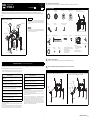
This manual describes the process of assembling a pad set and drum trigger module to
an already assembled electronic drum rack. Before starting the steps below, therefore,
be sure to assemble your electronic drum rack as described in the Owner’s Manual that
came with it.
Lay a drum mat (sold separately) on the floor underneath the hi-hat controller and the
kick pad. Alternatively, you can place cardboard from the drum kit packaging or the like
on the floor to prevent it from being scratched.
IMPORTANT
NOTICE
Example of standard assembly
Crash cymbal pad
Tom pad
Tom pads
Kick pad
Hi-hat controller
Drum trigger module
Hi-hat pad
Ride cymbal pad
Snare
pad
Electronic drum rack
The purpose of the precautions detailed below is to ensure that this electronic drum kit can be used safely without fear of injury or property damage. As a means of indicating the severity and immediacy
of any risk of injury or property damage resulting from incorrect operation, these precautions are classified as either WARNING or CAUTION. The instructions displayed together with these precautions
are extremely important in terms of ensuring safety, and therefore, they should be fully observed.
* After reading this Assembly Manual, ensure that it is kept in a safe, convenient location for future reference.
* Be sure to also read the Assembly Manuals and/or Owner’s Manuals that came with your pads and rack.
* The illustrations as shown in this manual are for instructional purposes only, and may appear somewhat dif-
ferent from those on your instrument.
* The company names and product names in this manual are the trademarks or registered trademarks of their
respective companies.
* The contents of this manual apply to the latest specifications as of the publishing date. To obtain the latest
manual, access the Yamaha website then download the manual file. Since specifications, equipment or sep-
arately sold accessories may not be the same in every locale, please check with your Yamaha dealer.
NOTICE: Usage Precautions
• When connecting and disconnecting cables, be sure to hold the plug and not the cable itself. In addition,
avoid placing heavy items on top of cables and do not allow them to touch sharp edges. Failure to avoid
these precautions can lead to cable breakage and disconnection.
• Do not climb onto the electronic drum kit and avoid placing heavy objects on it. Failure to observe this pre-
caution can result in malfunction.
• Avoid using or storing the electronic drum kit in very hot locations (i.e., in direct sunlight, in close proximity to
a heater, or in a closed vehicle) or in highly humid locations (i.e., in a bathroom or outdoors in wet weather).
Failure to observe this precaution can lead to warping, discoloration, malfunction, or breakdown.
• Avoid cleaning the electronic drum kit with organic solvents, paint thinner, or alcohol as these substances
can cause warping and discoloration. Instead, we recommend you remove dust using a soft dry cloth or
wipe clean using a moist, tightly-wrung cloth. If the electronic drum kit is very dirty, first wipe the dirt away
using a cloth moistened with a neutral detergent solution and tightly wrung. Following this, wipe away the
detergent solution using a cloth soaked in water and tightly wrung.
Safety Precautions Please read carefully before proceeding.
Failure to observe the precautions described below can result in se-
rious injury or even death.
• Young children using this electronic drum kit should be supervised by a guardian to eliminate any
possibility of injury.
• Holders for cymbal and tom pads have sharp tips. In order to avoid injury, therefore, you should
take special care whenever handling these components.
• The anti-slip stoppers on kick pads and foot pedals have sharp tips. In order to avoid injury, there-
fore, you should take special care whenever handling these components.
• Be sure to securely tighten nuts and other fasteners when setting up this electronic drum kit. In
addition, be sure to proceed slowly when loosening nuts. If this precaution is not observed, pads
may fall off or the rack may collapse or fall over, possibly causing injury.
• Do not setup this electronic drum kit on a slope, on an unstable platform, or on any other unsafe
surface. If this precaution is not observed, it may topple over or fall, possibly causing injury.
• Whenever setting up this electronic drum kit, ensure that cables and the like are arranged safely. If
someone were to trip on a cable, the kit could topple over and cause injury.
• Under no circumstances should this electronic drum kit be disassembled or customized. Failure to
observe this precaution can result in injury or malfunction.
• Do not sit or stand on the rack. Doing so could cause it to fall over or break, possibly causing injury.
WARNING
Failure to observe the precautions described below can result in in-
jury and/or property damage.
• Mind your fingers when adjusting clamps. They can easily be crushed if care is not taken during
this operation.
• Be careful with the tips of supports, arms, screws, and the like. Fingers can easily be injured by
sharp tips if these components are not handled carefully.
• Do not place hands or feet under a kick pad or foot pedal. Doing so could result in injury.
• Do not use the electronic drum kit’s rack to hold acoustic drums. Doing so could cause clamps to
break and the drums to fall off, which in turn could lead to injury.
CAUTION
Manual Development Group
© 2020 Yamaha Corporation
Published 04/2020
POMA*.*- **A0
VCR2740
Open the boxes to reveal their contents.
After opening up the packages containing your electronic drum kit, please verify that all of the following components are present.
Assemble the electronic drum rack.
For instructions on how to assemble the electronic drum rack, refer to the Owner’s Manual that came with it.
Assemble the hi-hat holder, the pads and the drum trigger module to the electronic drum rack.
1
Components of DTX6K-X
XP80 Snare Pad
(×1)
PCY135 Ride
Cymbal Pad (×1)
Hi-hat pad (×1) Crash cymbal pad
(×1)
Electronic drum rack (×1)
Electronic drum rack Owner’s Manual (×1)
HH65 Hi-hat
Controller (×1)
KP65 Kick Pad (×1) Nine-channel snake cable (×1)
Stopper for
PCY135 (×1)
Cable band (×6)
DTX6K-X Assembly Manual (this leaflet; x1)
PCY100 PCY135 PCY155 Owner’s Manual (×1)
HH65 Owner’s Manual (×1)
XP70 XP80 Owner’s Manual (×1)
TP70 Owner’s Manual (×1)
KP65 Owner’s Manual (×1)
DTX-PRO Drum Trigger Module (×1)
AC adaptor (×1)
* May not be included depending on
your particular area. Please check with
your Yamaha dealer.
DTX-PRO Owner’s Manual (×1)
Cubase AI Download information (×1)
Module holder (×1)
Module holder screw (×4)
TP70 Tom Pad (×3) Clamp bolt
(for XP80; ×1)
Drum key (×1)
Stopper for hi-hat pad and
crash cymbal pad (×2)
Wing bolt
(for TP70; ×3)
* Has a sticker labeled
“CRASH” on the rear side.
* The illustration shows the fully assembled rack.
2
3
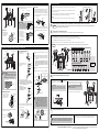
1. Remove the drum module clamp a and the left leg b from the left side of the rack. 2. Assemble the holder clamp for the hi-hat holder, ensuring that it is oriented as shown in the figure.
Following this, reassemble the left leg b and the drum module clamp a.
Drum module
clamp a
Left leg b
Drum module
clamp a
Left leg b
Holder clamp
Hi-hat holder
Assembling the hi-hat holder
Continued on other side

2
Snare pad
1. Attach a clamp bolt to
the snare pad and pro-
visionally tighten (by
five or six turns).
2. Attach the XP80 snare pad to the rod, and then tighten the
clamp bolt to secure the snare pad.
3. Loosen bolts A to D as
shown below to adjust
the height and angle of
the snare pad. When
correctly positioned, be
sure to securely retight-
en the bolts before pro-
ceeding to the next step.
Tom pads
1. As with the snare pad, attach a wing bolt to each of the three
tom pads and provisionally tighten (by five or six turns).
2. Push each of the tom pads onto one of the rack’s tom holders.
Each time, ensure that the tom holder’s rod is fully inserted
into the tom pad’s mounting hole, and then tighten the bolt to
secure the pad in place.
3. Loosen bolts A to C as shown below to adjust the height and
angle of each tom pad. When correctly positioned, be sure to
securely retighten the bolts before proceeding to the next
step.
XP80 snare pad
TP70 tom pads
Clamp bolt
(tighten in the
direction of the
arrow)
XP80 snare pad
(rear side)
Leave a gap of about a half inch
between the base of the rod and
the snare pad. Contact between
the rod section and snare pad
may cause damage to the pad.
Insert
XP80 snare pad
Clamp bolt
Rod section
NOTICE
Bolt B
Bolt D
Bolt C
Bolt A
TP70 tom pad
Insert
Wing bolt
Tom holder
Rod section
Bolt C
Bolt B
Bolt A
Assembling the snare and tom pads
Drum trigger module
1. Secure the module holder
to the bottom of the drum
trigger module using the
module holder screws.
2. Push the module holder into the holder clamp and tighten the
clamp bolt to secure it in place.
Each cymbal and hi-hat pad
1. Using the drum key, loosen
the stopper’s key bolt.
2. Remove the wing nut, the two felt
pads, and the bolt cover from the
cymbal holder.
3. Place the stopper on the cymbal holder.
* If the key bolt was not sufficiently loosened in Step 1
above, it may not be possible to pass the stopper over the
cymbal holder’s shaft. In such a case, loosen the key bolt
as much as possible without removing it.
4. Replace the bolt cover.
* Turn the bolt cover to tighten it
onto the threaded section and
firmly secure it in place.
5. With the stopper making full contact with the bottom surface
of the bolt cover as shown below, tighten the stopper’s key
bolt using the drum key.
6. Place one of the felt pads removed in Step 2 on the cymbal
holder.
7. Mount the pad on the cymbal stand. Lower the pad into place
with the cymbal holder’s shaft passing through the central
hole. When mounted, the stopper’s pin should rest inside the
pad’s smaller hole.
* If you were to play your cymbal pad without the stopper’s
pin positioned well inside the smaller hole, the pad could
rotate, causing the pin to be pulled out. It is very important,
therefore, to ensure that the stopper is secured as shown
in Step 5 above.
8. Assemble the other felt pad removed in Step 2 to the cymbal
holder.
9. Tighten the wing nut to secure the pad to the cymbal holder.
Crash cymbal pad
Drum trigger
module
PCY135 ride cymbal pad
Hi-hat pad
Difference between hi-hat pad and crash
cymbal pad:
Crash cymbal pad: Has a sticker labeled “CRASH”
on the rear side and has some bumps on the front
side.
Hi-hat pad: Has neither sticker nor bumps.
Sensor (bumps)
Crash cymbal pad
Module holder
screw (×4)
Module
holder
Drum trigger
module (rear
side)
Clamp bolt
Drum trigger module
+
module holder
Insert
Holder clamp
Clamp bolt
Key bolt
Stopper
Drum key
Wing nut
Felt pads
Bolt cover
Cymbal
holder
Bolt cover
Stopper
Threaded
section
Cymbal
holder
Cymbal holder
Stopper
Bolt cover
Full contact
Drum key
Cymbal pad
Felt pad removed
in Step 2
Cymbal holder
Felt pad removed
in Step 2
Bolt cover
Cymbal pad
Stopper
Pin
Wing nut
Stopper’s pin
Smaller hole
You can play comfortably by striking near the YAMA-
HA logo. Adjust the height, angle and orientation of
the cymbal pad and hi-hat pad to a position where
you can hit around the YAMAHA logo naturally when
performing. The correct setting position is that the
YAMAHA logo of the cymbal pad and hi-hat pad are
visible in front of the performer. The direction of the
cymbal pad and hi-hat pad will be appropriate by ad-
justing the direction of the stopper as shown below.
Stopper’s pin
YAMAHA
logo
Assembling the drum trigger module, cymbal pads, and hi-hat pad
Arrange the hi-hat controller and the kick pad as shown in Example of standard assembly on the other side of this sheet.
Lay a drum mat (sold separately) on the floor underneath the hi-hat controller and the kick pad. Alternatively, you can place cardboard from the drum kit packaging or the
like on the floor to prevent it from being scratched.
Connect the pads to the drum trigger module.
As described below, connect the output of each pad to the corresponding trigger input jack on the drum trigger module.
Connect the drum trigger module to a power supply.
Setting up the drum trigger module.
1. If a drum mat (sold separately) is not available, lay a sheet of cardboard on the floor to prevent it from being
scratched.
2. Remove the four wing bolts, spring washers, and flat washers from the kick pad frame, and line up each set
nearby in the order of removal.
3. Join the base to the frame as shown on the right, and then secure it in place by assembling the wing bolts,
spring washers, and flat washers removed in the previous step from the base side.
NOTE
For details on assembling the foot pedal (sold separately), refer to the “Setting Up” in the KP65 Owner’s Manual.
Assembling the kick pad
Frame
Frame
Base
Flat washerSpring washer
Wing bolt
4
NOTICE
5
1. Plug the straight ends of the nine-channel snake cable into the trigger input jacks on the back of the drum trigger module.
• When using the standard setup, the stickers on each of the snake cable’s plugs will indicate the name of the corresponding pad.
2. Plug the L-shaped ends of the nine-channel snake cable into the corresponding pads.
3. Wrap the cables for the snare pad, the tom pads, the cymbal pads and the hi-hat pad around the cable clips to prevent them from being pulled out.
Excessive bending can damage pad cables. Ensure, therefore, that these cables are not bent at an extreme angle when wrapped around the clips.
NOTICE
RIDE
TOM3
TOM2
KICK
TOM1
HH CON
SNARE
HI HAT
CRASH
HH CON HI HAT CRASH SNARE KICK TOM1 TOM2 RIDETOM3
KICK HH CON HI HAT CRASH RIDE TOM3 TOM2 TOM1 SNARE
Trigger input jacks on the drum module
Nine-channel
snake cable
6
1. Plug the AC adaptor’s DC cord into the connector. Hook
the AC adaptor’s DC cord around the cord clip to secure it in
place.
2. Using the cable bands, secure the cables to the electronic drum
rack at the positions circled in the figure on the right. ( )
3. Plug the adaptor’s AC cord into a domestic wall socket.
CAUTION
Excessive bending can damage AC adaptor’s DC cord. Ensure,
therefore, that the cord is not bent at an extreme angle when
wrapped around the clips. Doing so can cause fire or electrical
shock.
Drum trigger module’s rear panel
Cord clip
connector
If you secure the cable band from the side away
from the drum trigger module, you can make con-
nections more easily.
7
Select the “DTX6K-X” trigger setup on your drum trigger module. (For details on the trigger setup
procedure, refer to the “Initial Settings (Trigger Setup Wizard)” in the DTX-PRO Owner’s Manual.)
• Kick pad output (LEVEL) adjustment:
Adjust the trigger output to your desired setting by using the KP65 kick pad’s level adjustment
knob. For details, refer to the “Output Level Adjustment” in the KP65 Owner’s Manual.
The selection of the trigger setup is very important. Selecting the wrong trigger setup
will adversely affect your ability to perform comfortably. Use the correct trigger setup
that corresponds to your particular electronic drum kit for optimum performance.
Your electronic drum kit is now ready.
* For instructions on turning on the drum trigger module, producing sounds, and other subsequent steps,
please refer to the Owner’s Manual that came with the module.
-
 1
1
-
 2
2


Yamaha Electronic Drum Kit DTX6K-X Manuale utente
- Tipo
- Manuale utente
- Questo manuale è adatto anche per
in altre lingue
- English: Yamaha Electronic Drum Kit DTX6K-X User manual
- français: Yamaha Electronic Drum Kit DTX6K-X Manuel utilisateur
- español: Yamaha Electronic Drum Kit DTX6K-X Manual de usuario
- Deutsch: Yamaha Electronic Drum Kit DTX6K-X Benutzerhandbuch
- Nederlands: Yamaha Electronic Drum Kit DTX6K-X Handleiding
- português: Yamaha Electronic Drum Kit DTX6K-X Manual do usuário
- dansk: Yamaha Electronic Drum Kit DTX6K-X Brugermanual
- čeština: Yamaha Electronic Drum Kit DTX6K-X Uživatelský manuál
- polski: Yamaha Electronic Drum Kit DTX6K-X Instrukcja obsługi
- română: Yamaha Electronic Drum Kit DTX6K-X Manual de utilizare
Documenti correlati
-
Yamaha DTX532K Manuale del proprietario
-
-
-
-
-
-
-
-
Yamaha PCY155 Manuale del proprietario
-