Gigabyte GA-IMB460N Manuale del proprietario
- Tipo
- Manuale del proprietario

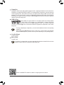
To reduce the impacts on global warming, the packaging materials of this product
are recyclable and reusable. GIGABYTE works with you to protect the environment.
For more product details, please visit GIGABYTE's website.
GA-IMB460N
User's Manual
Rev. 1001

Copyright
© 2020 GIGA-BYTE TECHNOLOGY CO., LTD. All rights reserved.
The trademarks mentioned in this manual are legally registered to their respective owners.
Disclaimer
Information in this manual is protected by copyright laws and is the property of GIGABYTE.
Changes to the specications and features in this manual may be made by GIGABYTE without
prior notice. No part of this manual may be reproduced, copied, translated, transmitted, or
published in any form or by any means without GIGABYTE's prior written permission.
In order to assist in the use of this product, carefully read the User's Manual.
For product-related information, check on our website at: https://www.gigabyte.com
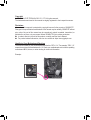
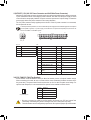
Identifying Your Motherboard Revision
The revision number on your motherboard looks like this: "REV: X.X." For example, "REV: 1.0"
means the revision of the motherboard is 1.0. Check your motherboard revision before updating
motherboard BIOS, drivers, or when looking for technical information.
Example:

- 3 -
Table of Contents
GA-IMB460N Motherboard Layout ..................................................................................4
Chapter 1 Hardware Installation .....................................................................................5
1-1 Installation Precautions .................................................................................... 5
1-2 ProductSpecications ...................................................................................... 6
1-3 Installing the CPU ............................................................................................ 9
1-4 Installing the Memory ....................................................................................... 9
1-5 Installing an Expansion Card ......................................................................... 10
1-6 Back Panel Connectors .................................................................................. 10
1-7 Internal Connectors ........................................................................................ 12
Chapter 2 BIOS Setup ..................................................................................................22
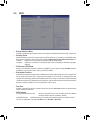
2-1 Startup Screen ............................................................................................... 22
2-2 The Main Menu .............................................................................................. 23
2-3 System ........................................................................................................... 24
2-4 Peripherals ..................................................................................................... 25
2-5 Chipset ........................................................................................................... 28
2-6 BIOS ............................................................................................................... 30
2-7 Power ............................................................................................................. 33
2-8 Save & Exit ..................................................................................................... 34
Chapter 3 Appendix ......................................................................................................35
3-1 ConguringaRAIDSet .................................................................................. 35
3-2 DriversInstallation .......................................................................................... 38
RegulatoryNotices .................................................................................................... 39
Contact Us ................................................................................................................ 40

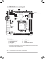
(Note) The chip/connector is located on the back of the motherboard.
- 4 -
GA-IMB460N Motherboard Layout
* The box contents above are for reference only and the actual items shall depend on the product package you obtain.
The box contents are subject to change without notice.
Box Contents
5GA-IMB460N motherboard 5Two SATA cables
5Motherboard driver disc 5I/O Shield
5User's Manual 5M.2 screw(s)/M.2 standoff(s)
5One COM port cable
ATX_12V
80
30_42
CPU_FAN
LGA1200
LVDS COMB_PW
COMA_PW
I2C
VOLUME_CONTROL
BAT
STB
BOOT
PCIEX16
Intel® B460
BIOS
SYS_FAN
GA-IMB460N
AUDIO
LCD_VCC
COMB
ATX
M2_M
U_SIM (Note)
M2 _E
SATA3 024
135
F_PANEL
MPCIE
DP_HDMI
F_AUDIO
CODEC
SPKR
BAT_CON
Intel®
GbE LAN
Intel®
GbE LAN
Nuvoton
Super I/O (Note)
F_USB2
F_USB1
F_USB3
GPIO
DDR4_1
DDR4_2
COMA
USB30_LANA
USB30_LANB
VGA
CI
SMBUS
AT_ATX
FPD
SPEAKER
MON_SW
CLR_CMOS

Chapter 1 Hardware Installation
1-1 Installation Precautions
The motherboard contains numerous delicate electronic circuits and components which can become
damagedasaresultofelectrostaticdischarge(ESD).Priortoinstallation,carefullyreadtheuser's
manual and follow these procedures:
•Prior to installation, make sure the chassis is suitable for the motherboard.
•Prior to installation, do not remove or break motherboard S/N (Serial Number) sticker or
warranty sticker provided by your dealer. These stickers are required for warranty validation.
•Always remove the AC power by unplugging the power cord from the power outlet before
installing or removing the motherboard or other hardware components.
•When connecting hardware components to the internal connectors on the motherboard, make
sure they are connected tightly and securely.
•When handling the motherboard, avoid touching any metal leads or connectors.
•It is best to wear an electrostatic discharge (ESD) wrist strap when handling electronic
componentssuchasamotherboard,CPUormemory.IfyoudonothaveanESDwriststrap,
keepyourhandsdryandrsttouchametalobjecttoeliminatestaticelectricity.
•Prior to installing the motherboard, please have it on top of an antistatic pad or within an
electrostatic shielding container.
•Before connecting or unplugging the power supply cable from the motherboard, make sure
the power supply has been turned off.
•Before turning on the power, make sure the power supply voltage has been set according to
the local voltage standard.
•Before using the product, please verify that all cables and power connectors of your hardware
components are connected.
•To prevent damage to the motherboard, do not allow screws to come in contact with the
motherboard circuit or its components.
•Make sure there are no leftover screws or metal components placed on the motherboard or
within the computer casing.
•Donotplacethecomputersystemonanunevensurface.
•Donotplacethecomputersysteminahigh-temperatureorwetenvironment.
•Turning on the computer power during the installation process can lead to damage to system
components as well as physical harm to the user.
•If you are uncertain about any installation steps or have a problem related to the use of the
product,pleaseconsultacertiedcomputertechnician.
•If you use an adapter, extension power cable, or power strip, ensure to consult with its installation
and/or grounding instructions.
- 5 -

1-2 ProductSpecications
CPU Support for 10th Generation Intel® Core™ i9 processors/Intel® Core™ i7 processors/
Intel® Core™ i5 processors/Intel® Core™ i3 processors/Intel® Pentium® processors/
Intel® Celeron® processors in the LGA1200 package
(Go to GIGABYTE's website for the latest CPU support list.)
L3 cache varies with CPU
Chipset Intel® B460 Express Chipset
Memory Intel® Core™ i9/i7 processors:
- SupportforDDR42933/2666/2400/2133MHzmemorymodules
Intel® Core™ i5/i3/Pentium®/Celeron® processors:
- SupportforDDR42666/2400/2133MHzmemorymodules
2xDDR4SO-DIMMsocketssupportingupto64GB(32GBsingleDIMMcapacity)
of system memory
Dualchannelmemoryarchitecture
(Go to GIGABYTE's website for the latest supported memory speeds and memory
modules.)
Onboard
Graphics
Integrated Graphics Processor-Intel®HDGraphicssupport:
- 1xD-Subport,supportingamaximumresolutionof1920x1200@60Hz
- 1xHDMIport,supportingamaximumresolutionof4096x2160@60Hz
* SupportforHDMI2.0version,HDCP2.2,andHDR.
- 1xDisplayPort,supportingamaximumresolutionof4096x2304@60Hz
* SupportforDisplayPort1.4version,HDCP2.3,andHDR.
Support for up to 3 displays at the same time
Maximum shared memory of 512 MB
Audio Realtek® ALC887 codec
HighDenitionAudio
2/4/5.1/7.1-channel
* Tocongure7.1-channelaudio,youneedtoopentheaudiosoftwareandselectDevice
advancedsettings>PlaybackDevicetochangethedefaultsettingrst.Pleasevisit
GIGABYTE'swebsitefordetailsonconguringtheaudiosoftware.
LAN 2 x Intel® GbE LAN chips (1000/100 Mbit)
Expansion Slots 1 x PCI Express x16 slot, running at x16
(The PCI Express x16 slot conforms to PCI Express 3.0 standard.)
1 x M.2 Socket 1 connector for the wireless communication module (M2_E)
1xfullsizeMiniPCIeconnector(MPCIE)
* The MPCIE connector can also be used as an MSATA connector.
* The MPCIE connector shares bandwidth with the SATA3 3 connector. When the
MPCIEconnectorisinstalledwithaMSATASSDconnector,theSATA33connector
becomes unavailable.
(The Mini PCI Express slot conforms to PCI Express 2.0 standard.)
- 6 -

Storage Interface Chipset:
- 1xM.2connector(Socket3,Mkey,type2242/2280SATAandPCIex2SSD
support) (M2_M)
- 6 x SATA 6Gb/s connectors
- SupportforSATARAID0,RAID1,RAID5,andRAID10
* Referto"1-7InternalConnectors,"fortheinstallationnoticesfortheM.2andSATA
connectors.
USB Chipset:
- 4 x USB 3.0/2.0 ports on the back panel
- 6 x USB 2.0/1.1 ports available through the internal USB headers
Internal
Connectors
1 x 24-pin ATX main power connector
1 x 4-pin ATX 12V power connector
1 x CPU fan header
1 x system fan header
1 x M.2 Socket 3 connector
6 x SATA 6Gb/s connectors
1 x MPCIE connector
1 x USIM connector on the back of the motherboard
1 x front panel header
1 x front panel audio header
1 x battery power cable connector
3 x USB 2.0/1.1 headers
2 x serial port headers
2 x serial port power select jumpers
1 x AT/ATX mode switch jumper (AT_ATX)
1 x GPIO header (GPIO)
1xLVDSheader(LVDS)
1xLVDSdrivevoltagejumper(LCD_VCC)
1xatpaneldisplayswitchheader(MON_SW)
1xatpaneldisplayheader(FPD)
1xspeakerheader(SPKR)
1xbuzzerheader(SPEAKER)
1 x Clear CMOS jumper
1 x chassis intrusion header
1xvolumecontrolheader(VOLUME_CONTROL)
1 x I2C jumper (I2C)
1 x SMBUS jumper (SMBUS)
Back Panel
Connectors
1xD-Subport
4 x USB 3.0/2.0 ports
2xRJ-45ports
1xHDMI2.0port
1xDisplayPort
2 x audio jacks
I/O Controller Nuvoton I/O Controller Chip
- 7 -

Hardware
Monitor
Voltage detection
Temperature detection
Fan speed detection
Fan speed control
* Whether the fan speed control function is supported will depend on the cooler you
install.
BIOS 1x128Mbitash
Use of licensed AMI UEFI BIOS
PnP1.0a,DMI2.7,WfM2.0,SMBIOS2.7,ACPI5.0
Unique Features Supportfor@BIOS
Support for Q-Flash
Bundled
Software Norton® Internet Security (OEM version)
Operating
System Support for Windows 10 64-bit
Form Factor Mini-ITX Form Factor; 17.0cm x 17.0cm
* GIGABYTEreservestherighttomakeanychangestotheproductspecicationsandproduct-relatedinformationwithout
prior notice.
Please visit GIGABYTE's website
for support lists of CPU, memory
modules,SSDs,andM.2devices.
Please visit the Support\Utility List
page on GIGABYTE's website to
download the latest version of apps.
- 8 -

1-3 Installing the CPU
ReadthefollowingguidelinesbeforeyoubegintoinstalltheCPU:
•Make sure that the motherboard supports the CPU.
(Go to GIGABYTE's website for the latest CPU support list.)
•Always turn off the computer and unplug the power cord from the power outlet before installing the
CPU to prevent hardware damage.
•Locate the pin one of the CPU. The CPU cannot be inserted if oriented incorrectly. (Or you may
locate the notches on both sides of the CPU and alignment keys on the CPU socket.)
•Apply an even and thin layer of thermal grease on the surface of the CPU.
•DonotturnonthecomputeriftheCPUcoolerisnotinstalled,otherwiseoverheatinganddamage
of the CPU may occur.
•SettheCPUhostfrequencyinaccordancewiththeCPUspecications.Itisnotrecommended
thatthesystembusfrequencybesetbeyondhardwarespecicationssinceitdoesnotmeetthe
standard requirements for the peripherals. If you wish to set the frequency beyond the standard
specications,pleasedosoaccordingtoyourhardwarespecicationsincludingtheCPU,graphics
card, memory, hard drive, etc.
Please visit GIGABYTE's website for details on hardware installation.
1-4 Installing the Memory
Readthefollowingguidelinesbeforeyoubegintoinstallthememory:
•Make sure that the motherboard supports the memory. It is recommended that memory of the same
capacity, brand, speed, and chips be used.
(Go to GIGABYTE's website for the latest supported memory speeds and memory modules.)
•Always turn off the computer and unplug the power cord from the power outlet before installing the
memory to prevent hardware damage.
•Memory modules have a foolproof design. A memory module can be installed in only one direction.
If you are unable to insert the memory, switch the direction.
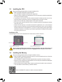
Installing the CPU
Locate the alignment keys on the motherboard CPU socket and the notches on the CPU.
Do not remove the CPU socket cover before inserting the CPU. It may pop off from the load
plate automatically during the process of re-engaging the lever after you insert the CPU.
Triangle Pin One Marking on the CPU
LGA1200 CPU
Alignment KeyAlignment Key
LGA1200 CPU Socket
Pin One Corner of the CPU Socket
Notch
Notch
- 9 -

1-5 Installing an Expansion Card
Readthefollowingguidelinesbeforeyoubegintoinstallanexpansioncard:
•Make sure the motherboard supports the expansion card. Carefully read the manual that came
with your expansion card.
•Always turn off the computer and unplug the power cord from the power outlet before installing an
expansion card to prevent hardware damage.
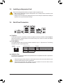
1-6 Back Panel Connectors
D-Sub Port
TheD-Subportsupportsa15-pinD-Subconnectorandsupportsamaximumresolutionof1920x1200@60Hz
(the actual resolutions supported depend on the monitor being used). Connect a monitor that supports
D-Subconnectiontothisport.
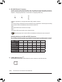
RJ-45 LAN Port
The Gigabit Ethernet LAN port provides Internet connection at up to 1 Gbps data rate. The following
describesthestatesoftheLANportLEDs.
USB 3.0/2.0 Port
TheUSB3.0/2.0portsupportstheUSB3.0/2.0specicationandiscompatibletotheUSB2.0specication.
Use this port for USB devices.
ActivityLED:Connection/SpeedLED:
State Description
Orange 1 Gbps data rate
Green 100 Mbps data rate
Off 10 Mbps data rate
State Description
Blinking Datatransmissionorreceivingisoccurring
On No data transmission or receiving is occurring
ActivityLED
Connection/
SpeedLED
LAN Port
•Whenremovingthecableconnectedtoabackpanelconnector,rstremovethecablefromyour
device and then remove it from the motherboard.
•Whenremovingthecable,pullitstraightoutfromtheconnector.Donotrockitsidetosideto
prevent an electrical short inside the cable connector.
- 10 -

PleasevisitGIGABYTE'swebsitefordetailsonconguringtheaudiosoftware.
DisplayPort
DisplayPortdelivershighqualitydigitalimagingandaudio,supportingbi-directionalaudiotransmission.
DisplayPortcansupportbothDPCPandHDCP2.3contentprotectionmechanisms.Itprovidesimproved
visualssupporting Rec. 2020(Wide ColorGamut) and HighDynamic Range (HDR)for Blu-ray UHD
playback.YoucanusethisporttoconnectyourDisplayPort-supportedmonitor.Note:TheDisplayPort
Technologycansupportamaximumresolutionof4096x2304@60Hzbuttheactualresolutionssupported
depend on the monitor being used.
HDMI 2.0 Port
TheHDMI port supports HDCP 2.2 and Dolby TrueHDand DTS HDMaster
Audioformats. It also supports upto 192KHz/16bit 7.1-channel LPCM audio
output.YoucanusethisporttoconnectyourHDMI-supportedmonitor.Themaximumsupported
resolutionis4096x2160@60 Hz, buttheactual resolutions supportedaredependent on the monitor
being used.
Line Out (Green)
The line out jack.
Mic In (Pink)
The Mic in jack.
• Tosetupatriple-displayconguration,youmustinstallmotherboarddriversintheoperating
systemrst.
• Afterinstalling the HDMI/DisplayPortdevice,make sure toset the defaultsoundplayback
devicetoHDMI/DisplayPort.(Theitemnamemaydifferdependingonyouroperatingsystem.)
Tocongure7.1-channelaudio,youneedtoopentheaudiosoftwareandselectDeviceadvanced
settings>PlaybackDevicetochangethedefaultsettingrst.
- 11 -

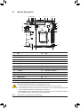
1-7 Internal Connectors
Readthefollowingguidelinesbeforeconnectingexternaldevices:
•First make sure your devices are compliant with the connectors you wish to connect.
•Before installing the devices, be sure to turn off the devices and your computer. Unplug the power
cord from the power outlet to prevent damage to the devices.
•After installing the device and before turning on the computer, make sure the device cable has
been securely attached to the connector on the motherboard.
1) ATX
2) ATX_12V
3) CPU_FAN
4) SYS_FAN
5) M2_M
6) U_SIM (Note)
7) SATA3 0/1/2/3/4/5
8) F_PANEL
9) F_AUDIO
10) BAT/BAT_CON
11) SPEAKER
12) COMA/COMB
13) LVDS
14) F_USB1/F_USB2/F_USB3
15) FPD
16) COMA/B_PW
17) GPIO
18) AT_ ATX
19) I2C
20) SMBUS
21) SPKR
22) LCD_VCC
23) VOLUME_CONTROL
24) MON_SW
25) CLR_CMOS
26) CI
27) STB/BOOT
(Note) The connector is on the back of the motherboard.
21 32
1 19
26
15
16
12
27
5
17
1820 622 7
23
4
8 14
9
24
11
25
13
10
- 12 -

DEBUG
PORT
G.QBOFM
13
1
24
12 ATX
ATX:
Pin No. Denition Pin No. Denition
1 3.3V 13 3.3V
2 3.3V 14 -12V
3GND 15 GND
4 +5V 16 PS_ON (soft On/Off)
5GND 17 GND
6 +5V 18 GND
7GND 19 GND
8 Power Good 20 NC
9 5VSB (stand by +5V) 21 +5V
10 +12V 22 +5V
11 +12V (Only for 2x12-pin
ATX)
23 +5V (Only for 2x12-pin ATX)
12 3.3V (Only for 2x12-pin ATX) 24 GND(Onlyfor2x12-pinATX)
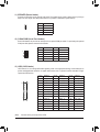
1/2) ATX/ATX_12V (2x2 12V Power Connector and 2x12 Main Power Connector)
With the use of the power connector, the power supply can supply enough stable power to all the components
onthemotherboard.Beforeconnectingthepowerconnector,rstmakesurethepowersupplyisturned
off and all devices are properly installed. The power connector possesses a foolproof design. Connect the
power supply cable to the power connector in the correct orientation.
The 12V power connector mainly supplies power to the CPU. If the 12V power connector is not connected,
the computer will not start.
To meet expansion requirements, it is recommended that a power supply that can withstand high power consumption
be used (500W or greater). If a power supply is used that does not provide the required power, the result can
lead to an unstable or unbootable system.
ATX_12V:
Pin No. Denition
1GND
2GND
3 +12V
4 +12V
ATX_12V
2
1
4
3
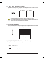
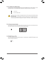
3/4) CPU_FAN/SYS_FAN (Fan Headers)
All fan headers on this motherboard are 4-pin. Most fan headers possess a foolproof insertion design.
When connecting a fan cable, be sure to connect it in the correct orientation (the black connector wire is
the ground wire). The speed control function requires the use of a fan with fan speed control design. For
optimum heat dissipation, it is recommended that a system fan be installed inside the chassis.
•Be sure to connect fan cables to the fan headers to prevent your CPU and system from
overheating. Overheating may result in damage to the CPU or the system may hang.
•Thesefanheadersarenotcongurationjumperblocks.Donotplaceajumpercapontheheaders.
Pin No. Denition
1GND
2 Voltage Speed Control
3 Sense
4 PWM Speed Control
CPU_FAN/SYS_FAN
DEBUG
PORT
G.QBOFM
1
- 13 -

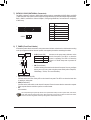
SelecttheproperholefortheM.2SSDtobeinstalledandrefastenthescrewandstandoff.
5) M2_M (M.2 Socket 3 Connector)
TheM.2connectorsupportsM.2SATASSDsorM.2PCIeSSDsandsupportsSATARAIDconguration.
PleasenotethatanM.2PCIeSSDcannotbeusedtocreateaRAIDsetwithaSATAharddrive.Referto
Chapter3,"ConguringaRAIDSet,"forinstructionsonconguringaRAIDarray.
FollowthestepsbelowtocorrectlyinstallanM.2SSDintheM.2connector.
Step 1:
Use a screw driver to unfasten the screw and standoff from the motherboard. Locate the proper mounting
holefortheM.2SSDtobeinstalledandthenscrewthestandoffrst.
Step 2:
SlidetheM.2SSDintotheconnectoratanangle.
Step 3:
PresstheM.2SSDdownandthensecureitwiththescrew.
F_USB30 F_U
B_
F_ F_
_
B
BS_
B
SB_
B
_S
S_
_
B
_U
_
B
S
123
123
123
123
1
1
1
1
BSS
S
_S
SSU
1 2 3
S3 BSSS
U
__ 3
F_USB3F
S _
S _
S _
SF
B_
B_
F
_0
S
S
_0F
_F
_
_
__B
U
S _S
_ SF_
B
USB0_B
B_
B_
F_USB3
F_USB303
_
_3U
S_
80 42
(Note) The connector is on the back of the motherboard.
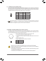
6) USIM (USIM Connector) (Note)
This connector can be used to install a Micro Sim card to connect to a mini PCIe LAN card.
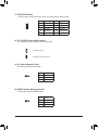
SATA3 0 SATA3 1 SATA3 2 SATA3 3 SATA3 4 SATA3 5
M.2SATASSD aaaa
M.2PCIex2SSD
aaaaaa
NoM.2SSDInstalled aaaaaa
MSATASSD a a a r a a
a: Available, r: Not available
Connector
Type of
M.2SSD
Installation Notices for the M.2 and SATA Connectors:
The availability of the SATA connectors may be affected by the type of device installed in the M.2 connector.
TheM.2connectorsharesbandwidthwiththeSATA32connector.Refertothefollowingtablefordetails.
- 14 -

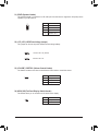
7) SATA3 0/1/2/3/4/5 (SATA 6Gb/s Connectors)
The SATA connectors conform to SATA 6Gb/s standard and are compatible with SATA 3Gb/s and SATA
1.5Gb/s standard. Each SATA connector supports a single SATA device. The Intel®ChipsetsupportsRAID0,
RAID1,RAID5,andRAID10.RefertoChapter3,"ConguringaRAIDSet,"forinstructionsonconguring
aRAIDarray.
Pin No. Denition
1GND
2 TXP
3 TXN
4GND
5RXN
6RXP
7GND
8) F_PANEL (Front Panel Header)
Connect the power switch, reset switch, and system status indicator on the chassis to this header according
to the pin assignments below. Note the positive and negative pins before connecting the cables.
The front panel design may differ by chassis. A front panel module mainly consists of power switch, reset switch,
powerLED,harddriveactivityLEDandetc.Whenconnectingyourchassisfrontpanelmoduletothisheader,
make sure the wire assignments and the pin assignments are matched correctly.
•PW (Power Switch):
Connectstothepowerswitchonthechassisfrontpanel.Youmaycongure
the way to turn off your system using the power switch (refer to Chapter 2,
"BIOSSetup,""Power,"formoreinformation).
•PLED(PowerLED):
System Status LED
S0 On
S3/S4/S5 Off
Connects to the power status indicator on the
chassisfront panel. The LED is onwhen the
systemisoperating.The LED isoffwhenthe
system is in S3/S4 sleep state or powered off
(S5).
9
NC
PLED-
PW-
PLED+
PW+
HD-
RES+
HD+
RES-
Power Switch
HardDrive
ActivityLED
ResetSwitch
PowerLED
10
1
2
•HD (HardDriveActivityLED):
ConnectstotheharddriveactivityLEDonthechassisfrontpanel.TheLEDisonwhentheharddrive
is reading or writing data.
•RES (ResetSwitch):
Connects to the reset switch on the chassis front panel. Press the reset switch to restart the computer
ifthecomputerfreezesandfailstoperformanormalrestart.
•NC:
No connection.
DEBUG
PORT
G.QBOFM
DEBUG
PORT
G.QBOFM
DEBUG
PORT
G.QBOFM
DEBUG
PORT
G.QBOFM
DEBUG
PORT
G.QBOFM
DEBUG
PORT
G.QBOFM
1
1
7
7
SATA3 024
135
- 15 -

9) F_AUDIO (Front Panel Audio Header)
ThefrontpanelaudioheadersupportsHighDenitionaudio(HD).Youmayconnectyourchassisfront
panel audio module to this header. Make sure the wire assignments of the module connector match the
pin assignments of the motherboard header. Incorrect connection between the module connector and the
motherboard header will make the device unable to work or even damage it.
Some chassis provide a front panel audio module that has separated connectors on each wire
instead of a single plug. For information about connecting the front panel audio module that has
different wire assignments, please contact the chassis manufacturer.
Pin No. Denition Pin No. Denition
1 MIC2_L 6 Sense
2GND 7FAUDIO_JD
3MIC2_R 8 No Pin
4-ACZ_DET 9 LINE2_L
5LINE2_R 10 Sense
12
910
Pin No. Denition
1(+) RTCPower
2(-) GND
10) BAT/BAT_CON (Battery/Battery Power Cable Connector)
Thebatteryprovidespowertokeepthevalues(suchasBIOScongurations,date,andtimeinformation)
intheCMOSwhenthecomputeristurnedoff.Replacethebatterywhenthebatteryvoltagedropstoalow
level, or the CMOS values may not be accurate or may be lost.
You may clear the CMOS values by removing the battery cable:
1. Turn off your computer and unplug the power cord.
2. Unplug the the battery cable from the battery cable header and wait for one
minute.
3. Plug in the battery cable.
4. Plug in the power cord and restart your computer.
•Always turn off your computer and unplug the power cord before replacing the battery.
•Replacethebatterywithanequivalentone.Damagetoyourdevicesmayoccurifthebatteryis
replaced with an incorrect model.
•Contact the place of purchase or local dealer if you are not able to replace the battery by yourself
or uncertain about the battery model.
•Used batteries must be handled in accordance with local environmental regulations.
F_USB30 F_U
B_
F_ F_
_
B
BS_
B
SB_
B
_S
S_
_
B
_U
_
B
S
123
123
123
123
1
1
1
1
BSS
S
_S
SSU
1 2 3
S3 BSSS
U
__ 3
F_USB3F
S _
S _
S _
SF
B_
B_
F
_0
S
S
_0F
_F
_
_
__B
U
S _S
_ SF_
B
USB0_B
B_
B_
F_USB3
F_USB303
_
_3U
S_
1(+)
2(-)
- 16 -

12) COMA/COMB (Serial Port Headers)
Each COM header can provide one serial port via an optional COM port cable. For purchasing the optional
COM port cable, please contact the local dealer.
Pin No. Denition Pin No. Denition
1NDCD- 6 NCTS-
2NDSR- 7NDTR-
3 NSIN 8 12V_5V
4NRTS- 9GND
5 NSOUT 10 NC
11) SPEAKER (Buzzer Header)
Connectstothebuzzeronthechassisfrontpanel.Thesystemreportssystemstartupstatusbyissuinga
beep code. One single short beep will be heard if no problem is detected at system startup.
Pin No. Denition
1 VCC
2 NC
3 NC
4 SPK-
13) LVDS (LVDS Header)
LVDSstandsforLow-voltagedifferentialsignaling,whichuseshigh-speedanalogcircuittechniquesto
provide multigigabit data transfers on copper interconnects and is a generic interface standard for high-
speed data transmission.
(Note) ConnectstothegroundpinoftheLVDS.
Pin No. Denition Pin No. Denition Pin No. Denition
1LCD_VCC 15 -RXO3_C 29 CABLE_DET(Note)
2LCD_VCC 16 +RXO3_C 30 -RXE3_C
3 VCC3 17 GND 31 +RXE3_C
4 NC 18 -RXECLKO_C 32 GND
5 NC 19 +RXECLKO_C 33 -RXECLKE_C
6-RXO0_C 20 GND 34 +RXECLKE_C
7+RXO0_C 21 -RXE0_C 35 GND
8GND 22 +RXE0_C 36 SC_BKLT_EN
9-RXO1_C 23 GND 37 SC_BKLT_CTL
10 +RXO1_C 24 -RXE1_C 38 FPD_PWR
11 GND 25 +RXE1_C 39 FPD_PWR
12 -RXO2_C 26 GND 40 FPD_PWR
13 +RXO2_C 27 -RXE2_C
14 GND 28 +RXE2_C
109
21
DEBUG
PORT
G.QBOFM
1
21
4039
- 17 -

15) FPD (Flat Panel Display Header)
TheFPDisahigh-speedinterfaceconnectingtheoutputofavideocontrollerinalaptopcomputer,computer
monitororLCDtelevisionsettothedisplaypanel.Mostlaptops,LCDcomputermonitorsandLCDTVsuse
thisinterfaceinternally.TheheaderconformstoFPDspecication.
Pin No. Denition
1 BKLT_EN
2 BKLT_PWM
3BKLT_PWR(FPD_PWR)
4BKLT_PWR(FPD_PWR)
5BKLT_GND/Brightness_GND
6BKLT_GND/Brightness_GND
7 Brightness_Up
8Brightness_Down
16) COMA_PW/COMB_PW (Serial Port Header Power Select Jumpers)
The power select jumpers are used to select serial port power.
1-2 Close: Set to 12V.
2-3Close:Setto5V.(Default)
1
1
14) F_USB1/F_USB2/F_USB3 (USB 2.0/1.1 Headers)
TheheadersconformtoUSB2.0/1.1specication.EachUSBheadercanprovidetwoUSBportsviaan
optional USB bracket. For purchasing the optional USB bracket, please contact the local dealer.
Pin No. Denition Pin No. Denition
1 Power (5V) 6 USBDY+
2 Power (5V) 7 GND
3USBDX- 8GND
4USBDY- 9 No Pin
5USBDX+ 10 NC
•DonotplugtheIEEE1394bracket(2x5-pin)cableintotheUSB2.0/1.1header.
•Prior to installing the USB bracket, be sure to turn off your computer and unplug the power cord
from the power outlet to prevent damage to the USB bracket.
1
210
9
1
8
- 18 -

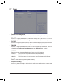
19) I2C (Inter-Integrated Circuit)
This header provides the I2C signals.
Pin No. Denition
1 I2C_SCL
2I2C_SDA
3GND
20) SMBUS (System Management Bus)
This header provides the SMBUS signals.
Pin No. Denition
1 SMB_CLK
2SMB_DATA
3GND
17) GPIO (GPIO Header)
Use this jumper to set the GPIO status of the LPT_GPIO header to HIGH or LOW.
18) AT_ATX (ATX Power Switch Jumper)
This jumper allows you to select AT or ATX power mode.
1-2 Close: AT mode.
2-3Close:ATXmode.(Default)
Pin No. Denition Pin No. Denition
1 IO_GP70 6 IO_GP75
2 IO_GP71 7 IO_GP76
3 IO_GP72 8 IO_GP77
4 IO_GP73 9 GP_IN_OUT
5 IO_GP74 10 GND
1
1
1
1
109
21
- 19 -

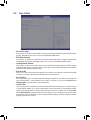
22) LCD_VCC (LVDS Drive Voltage Jumper)
This jumper can be used to provide different screen voltage settings.
1
1
1-2Close:Setto3V.(Default)
2-3 Close: Set to 5V.
23) VOLUME_CONTROL (Volume Control Header)
The header connects to the volume control button of the monitor to control the volume.
Pin No. Denition
1VOL_DOWN
2GND
3 VOL_UP
21) SPKR (Speaker Header)
ThisspeakerheaderisconnectedtoaL/Raudiopinsfromtheboardtosupportthe3W(4ohm)stereo
speaker on your AIO chassis.
1
4Pin No. Denition
1SpeakerOUTR-
2SpeakerOUTR+
3 Speaker OUT L-
4 Speaker OUT L+
24) MON_SW (Flat Panel Display Switch Header)
This header allows you to connect an on/off switch for the display.
Pin No. Denition
1 Mon_SW
2GND
1
1
- 20 -
La pagina si sta caricando...
La pagina si sta caricando...
La pagina si sta caricando...
La pagina si sta caricando...
La pagina si sta caricando...
La pagina si sta caricando...
La pagina si sta caricando...
La pagina si sta caricando...
La pagina si sta caricando...
La pagina si sta caricando...
La pagina si sta caricando...
La pagina si sta caricando...
La pagina si sta caricando...
La pagina si sta caricando...
La pagina si sta caricando...
La pagina si sta caricando...
La pagina si sta caricando...
La pagina si sta caricando...
La pagina si sta caricando...
La pagina si sta caricando...
-
 1
1
-
 2
2
-
 3
3
-
 4
4
-
 5
5
-
 6
6
-
 7
7
-
 8
8
-
 9
9
-
 10
10
-
 11
11
-
 12
12
-
 13
13
-
 14
14
-
 15
15
-
 16
16
-
 17
17
-
 18
18
-
 19
19
-
 20
20
-
 21
21
-
 22
22
-
 23
23
-
 24
24
-
 25
25
-
 26
26
-
 27
27
-
 28
28
-
 29
29
-
 30
30
-
 31
31
-
 32
32
-
 33
33
-
 34
34
-
 35
35
-
 36
36
-
 37
37
-
 38
38
-
 39
39
-
 40
40


Gigabyte GA-IMB460N Manuale del proprietario
- Tipo
- Manuale del proprietario
in altre lingue
- English: Gigabyte GA-IMB460N Owner's manual
Documenti correlati
-
Gigabyte GA-IMB410TN Manuale del proprietario
-
-
-
Gigabyte H510M H Manuale del proprietario
-
-
-
-
-
Gigabyte GA-H61M-DS2 Manuale del proprietario
-