Quantum GAS-FIRED BOILERS Manuale utente
- Categoria
- Scaldabagno
- Tipo
- Manuale utente
Questo manuale è adatto anche per

DUNKIRK BOILERS
DUNKIRK, NEW YORK 14048 - 716 366-5500
Member: The Hydronics Institute
GAS-FIRED, DIRECT VENT, CONDENSING, HOT WATER
BOILERS
INSTALLATION INSTRUCTIONS
These instructions must be affixed on or adjacent to the boiler
WARNING
Improper installation, adjustment, alteration, service, or maintenance can cause injury or
property damage. Refer to this manual. For assistance or additional information consult a
qualified installer, service agency, or gas supplier.


1
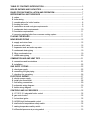
TABLE OF CONTENTS INTRODUCTION ............................................................................. 3
BOILER RATINGS AND CAPACITIES .................................................................................. 4
RULES FOR SAFE INSTALLATION AND OPERATION....................................................... 7
BEFORE INSTALLING THE BOILER .................................................................................... 7
A. codes ............................................................................................................................... 7
B. boiler sizing ...................................................................................................................... 8
C. considerations for boiler location ..................................................................................... 8
D. locating the boiler ............................................................................................................ 8
E. combustion air and vent pipe requirements ..................................................................... 9
F. condensate drain requirements...................................................................................... 10
G. foundation requirements ................................................................................................ 11
H. removing existing boiler from common venting system ................................................. 11
PLACING THE BOILER ....................................................................................................... 11
NEAR BOILER PIPING ........................................................................................................ 12
A. supply and return lines................................................................................................... 12
B. pressure relief valve ....................................................................................................... 16
C. expansion tank and make-up water ............................................................................... 16
D. condensate drain piping ................................................................................................ 19
E. filling condensate trap .................................................................................................... 19
F. chilled water piping ........................................................................................................ 20
COMBUSTION AIR AND VENT PIPE .................................................................................. 21
A. connections and terminations ........................................................................................ 21
B. installation ...................................................................................................................... 22
GAS SUPPLY PIPING .......................................................................................................... 25
A. check gas supply ........................................................................................................... 25
B. connecting the gas piping .............................................................................................. 25
C. checking the gas piping ................................................................................................. 26
ELECTRICAL WIRING ......................................................................................................... 27
A. electric power supply ..................................................................................................... 27
B. install your thermostat.................................................................................................... 28
C. field wiring connections ................................................................................................. 29
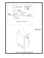
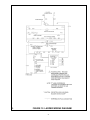
D. schematic wiring diagram .............................................................................................. 30
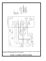
E. ladder wiring diagram..................................................................................................... 31
CONTROLS AND ACCESSORIES ...................................................................................... 32
A. UT 1013-10 integrated boiler control ............................................................................ 32
B. gas control valve ............................................................................................................32
C. hot surface igniter ..........................................................................................................32
D. L4006A high limit aquastat control ................................................................................ 32
E. draft inducer temperature safety switch ......................................................................... 32
F. casting temperature safety switch .................................................................................. 33
G. differential pressure air proving switch .......................................................................... 33

2
H. draft inducer...................................................................................................................... 33
I. circulator pump.................................................................................................................. 33
J. drain valve......................................................................................................................... 33
K. relief valve........................................................................................................................ 34
L. flame rollout safety shutoff................................................................................................ 34
M. external condensate pump............................................................................................... 34
START-UP.............................................................................................................................. 34
A. water treatment and freeze protection.............................................................................. 34
B. filling boiler with water and purging air with diaphragm type expansion tanks.................. 35
C. filling boiler with water and purging air with conventional closed type expansion tanks.... 35
D. boiler in placing.................................................................................................................. 36
I. for your safety read before operating
II. operating instructions
III. to turn off gas to appliance
CHECK-OUT PROCEDURES AND ADJUSTMENTS............................................................ 37
A. verify proper sequence of operation.................................................................................. 37
B. inspect venting and air intake system................................................................................ 38
C. inspect condensate drain...................................................................................................38
D. inspect system piping.........................................................................................................38
E. test ignition system safety shutoff...................................................................................... 38
F. test high limit control and adjust.........................................................................................38
G. test other safety controls....................................................................................................39
H. set thermostat heat............................................................................................................ 39
1. measure the gas input rate................................................................................................39
J. set thermostat to desired room temperature......................................................................41
K. review all instructions........................................................................................................ 41
L. installation and check-out certificate.................................................................................. 41
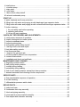
MAINTENANCE AND CLEANING.......................................................................................... 43
A. beginning of each season.................................................................................................. 43
B. daily during heating season............................................................................................... 43
C. monthly during heating...................................................................................................... 44
D. periodically during heating................................................................................................. 44
E. end of each heating season -annual shut down procedure............................................... 44
F. annual examination and cleaning of boiler components.................................................... 44
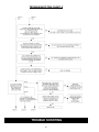
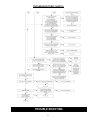
SERVICE HINTS...................................................................................................................... 47
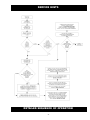
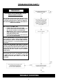
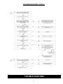
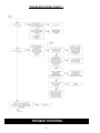
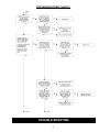
A flow chart/detailed sequence of operation......................................................................... 47
B. trouble shooting................................................................................................................. 50
C. differential air pressure switch check................................................................................. 58
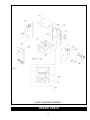
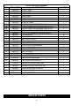
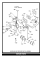
REPAIR PARTS.......................................................................................................................59
A. jacket and base..................................................................................................................59
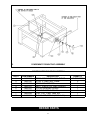
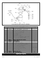
B. condensate drain trap assembly ....................................................................................... 61
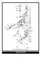
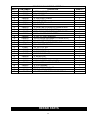
C. block and piping assembly.................................................................................................62
D. mixer and air pressure switch assembly............................................................................ 64
E. flue adapter and exhauster assembly................................................................................ 66

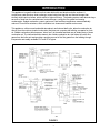
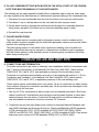
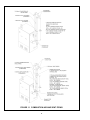
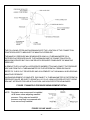
This appliance is a gas-fired direct vent hot water boiler with cast aluminum boiler sections. A
revolutionary cast aluminum heat exchanger means better heat transfer and thermal storage than
similarly sized cast iron boilers, which results in higher efficiency. The heating system water absorbs large
amounts of heat from the cast aluminum heat exchanger, cooling the flue gases and causing
condensation. Sealed combustion, premix gas burner, and low flame temperature means drastically
reduced CO and NOx emissions, which contribute to a cleaner and healthier environment.
This appliance, unlike normal residential atmospheric and induced draft units, takes its combustion air
directly from the outdoors (sealed combustion) and does not compete with building occupants for fresh
air. Sealed combustion (also known as direct vent) is the safest and best way to obtain plenty of clean
combustion air. The induced draft fan draws in the outside combustion air, then takes the cooler flue
gases from the boiler unit and provides a positive removal of the flue gases from the building through
inexpensive and readily available PVC and CPVC pipes.
3
FIGURE 1
INTRODUCTION

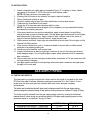
BOILER RATINGS AND CAPACITIES
4
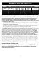
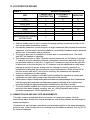
These low pressure gas-fired hot water boilers are design certified by CSA International for use
with natural and propane gases. The boilers are constructed and hydrostatically tested for a
maximum working pressure of 50 psig (pounds per square inch gage) in accordance with
A.S.M.E. (American Society of Mechanical Engineers) Boiler and Pressure Vessel Code Section
IV Standards for heating boilers.
++ AFUE (Annual Fuel Utilization Efficiency) and Heating Capacity is based on the D.O.E.
(Department of Energy) test procedure.
The Boilers are certified in accordance with ANSI (American National Standards Institute)
Z21.13 standards as gas-fired, direct vent, condensing, hot water boilers.
The Heating Capacity indicates the amount of heat available after subtracting the losses up the
stack. Most of this heat is available to heat water. A small portion is heat from the jacket and
surfaces of the boiler, and it is assumed that this heat stays in the structure. The Net I=B=R
Rating represents the portion of the remaining heat that can be applied to heat the radiation or
terminal units (i.e. finned tube baseboard, cast iron radiators, radiant floor, etc.). The difference
between the Heating Capacity and the Net I=B=R Rating, called the piping and pickup
allowance, establishes a reserve for heating the volume of water in the system and offsetting
heat losses from the piping. The Net I=B R Ratings shown are based on a piping and pickup
factor of 1.15 in accordance with the I=B=R Standard as published by the Hydronics Institute.
The Net I=B=R Rating of the boiler selected should be greater than or equal to the calculated
peak heating load (heat loss) for the building or area(s) served by the boiler and associated hot
water heating systems. The manufacturer should be consulted before selecting a boiler for
installations having unusual piping and pickup requirements.
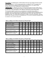
BOILERS FOR USE AT HIGH ALTITUDE
The boilers are factory equipped for operation at altitudes ranging from 0-2,000 feet above sea
level. For use of these boilers at altitudes above 2,000 feet above sea level, the gas input
ratings (MBH) must be reduced.
0RGHO ,QSXW0%+
+HDWLQJ
&DSDFLW\
0%+
1HW, % 5
5DWLQJ
0%+
6KLSSLQJ
:HLJKW
OEV
)OXH
'LD
´&39&39&
´&39&39&
´&39&39&
7$%/(6($/(9(/5$7,1*61$785$/$1'3523$1(*$6(6
0%+ %WXK%WXK %ULWLVK7KHUPDO8QLWV3HU+RXU

5
U.S.A. ONLY: For altitudes above 2,000 feet above sea level, input ratings should be reduced
as shown in tables IA, C, & E for natural gas boilers or in tables 1B, D & F for propane fired
boilers. Reduced input ratings are achieved by the natural deration of the gas at higher
elevations and fine tuned by adjusting the manifold pressure.
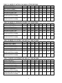
CANADA ONLY: For altitudes in the range of 2,000-4,500 feet above sea level, boilers may be
field equipped for use at high altitude by using a certified high altitude conversion kit. The change
in main burner orifice size results in a 10% reduction of the boiler gas input rating (MBH).
The conversion shall be carried out by a manufacturers authorized representative, in
accordance with the requirements of the manufacturer, provincial or territorial authorities having
jurisdiction, and in accordance with the requirements of the CSA-B 149.1 and CSA-B 149.2
Installation Codes. The certified field conversion kit includes a conversion data plate, indicating
that the boiler has been converted for high altitude use. The correct conversion information must
be entered on the conversion data plate.
(/(9$7,21)((7
120,1$/,13870%+
+($7&$3&,7<0%+
1(7, % 55$7,1*0%+
*$625,),&('5,//6,=(
0$1,)2/'35(6685(
,1&+(6:$7(5&2/801
35(6685(6:,7&+6(732,17
,1&+(6:$7(5&2/801
(/(9$7,21)((7
120,1$/,13870%+
+($7&$3&,7<0%+
1(7, % 55$7,1*0%+
*$625,),&('5,//6,=(
0$1,)2/'35(6685(
,1&+(6:$7(5&2/801
35(6685(6:,7&+6(732,17
,1&+(6:$7(5&2/801
7$%/(%02'(/3523$1(*$6+,*+$/7,78'(5$7,1*6
7$%/($02'(/1$785$/*$6+,*+$/7 ,78'(5$7,1*6

6
(/(9$7,21)((7
120,1$/,13870%+
+($7&$3&,7<0%+
1(7, % 55$7,1*0%+
*$625,),&('5,//6,=(
0$1,)2/'35(6685(
,1&+(6:$7(5&2/801
35(6685(6:,7&+6(732,17
,1&+(6:$7(5&2/801
(/(9$7,21)((7
120,1$/,13870%+
+($7&$3&,7<0%+
1(7, % 55$7,1*0%+
*$625,),&('5,//6,=(
0$1,)2/'35(6685(
,1&+(6:$7(5&2/801
35(6685(6:,7&+6(732,17
,1&+(6:$7(5&2/801
(/(9$7,21)((7
120,1$/,13870%+
+($7&$3&,7<0%+
1(7, % 55$7,1*0%+
*$625,),&('5,//6,=(
0$1,)2/'35(6685(
,1&+(6:$7(5&2/801
35(6685(6:,7&+6(732,17
,1&+(6:$7(5&2/801
(/(9$7,21)((7
120,1$/,13870%+
+($7&$3&,7<0%+
1(7, % 55$7,1*0%+
*$625,),&('5,//6,=(
0$1,)2/'35(6685(
,1&+(6:$7(5&2/801
35(6685(6:,7&+6(732,17
,1&+(6:$7(5&2/801
7$%/()02'(/3523$1(*$6+,*+$/7,78'(5$7,1*6
7$%/((02'(/1$785$/*$6+,*+$/7,78'(5$7 ,1*6
7$%/('02'(/3523$1(*$6+,*+$/7,78'(5$7,1*6
7$%/(&02'(/1$785$/*$6+,*+$/7,78'(5$7 , 1*6

7
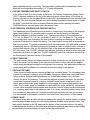
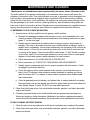
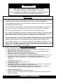
l. Read the entire installation manual before beginning the installation. Failure to follow these
rules for safe installation and operation and these instructions could cause a malfunction of
the boiler and result in death, serious bodily injury, and/or property damage.
2. Check all applicable state and local building codes and utility company requirements
before installation. The installation must conform with these requirements in their
entirety. In the absence of these codes, use NFPA Installation Codes and good
industry practice.
3. Before servicing the boiler - allow the boiler to cool. Always shut off any electricity and
gas supply connected to the boiler prior to servicing.
4. Inspect gas line for leaks.
5. Be certain gas input rate is correct. Over firing may result in early failure of the boiler
sections. This may cause dangerous operation. Under firing may result in too much air
for the pre-mix burner causing poor or loss of combustion.
6. Never vent the products of combustion from this boiler to an enclosed space. Always
vent to the outdoors. Never vent to another room or to inside a building.
7. Be sure there is adequate outdoor air supply to boiler.for complete combustion.
8. Follow a regular service and maintenance schedule for efficient and safe operation. 9.
Keep boiler area clean of debris and free of combustible and flammable materials.
10. Proper through the wall or through the roof combustion venting shall be in accordance with the
materials and methods described in this manual. Installation must comply with local codes.
11. This boiler and related hot water heating systems are not do it yourself items. They
must be installed and serviced by qualified professionals.
WARNING
This boiler has been equipped for residential installations. If used for commercial applications, any
additional code requirements must be adhered to for installation. This may require additional
controls including but not limited to a low water cut off, a manual reset high temperature limit, and
wiring and/or piping modifications. The manufacturer is not responsible for any field installation
changes made to a boiler installation which are not described or acknowledged in this manual.
Complete all of the following prior to installing the boiler.
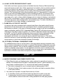
A. CODES
This boiler product is a gas-fired, direct vent, condensing boiler and must be installed in
accordance with all applicable federal, state and local building codes including, but not
limited to the following:
United States -Installation shall conform with National Fuel Gas Code (NFPA-54/ANSI
Z223.1-latest edition)
Canada - Installation shall be in accordance with CSA B 149.1 and .2. installation
codes.
RULES FOR SAFE INSTALLATION AND OPERATION
BEFORE INSTALLING THE BOILER

Where required by the authority having jurisdiction, the installation must conform to the
American Society of Mechanical Engineers Safety Code for Controls and Safety Devices
for Automatically Fired Boilers, No.CSD-1.
The installation must conform to the requirements of the authority having jurisdiction or, in the
absence of such requirements, to the National Fuel Gas Code, ANSI Z223.1 - latest revision.
Installers - Follow local regulations with respect to installation of CO (Carbon
Monoxide) Detectors. Follow maintenance recommendations in this manual.
Techniciens -Veuillez vous conformer à la réglementation en vigueur concernant 1'
installations des détecteurs d'oxyde de carbone. Suivre les consignes
d'entretien figurant dans le manuel d'instruction ci-joint.
B. BOILER SIZING
• Check to be sure you have selected the boiler with the proper capacity before starting
the installation. The I=B R Rating of the boiler selected should be greater than or equal
to the calculated peak heating load (heat loss) for the building or area(s) served by the
boiler and associated hot water heating systems. See the table "BOILER RATINGS
AND CAPACITIES".
• Heat loss calculations should be based on approved industry methods.
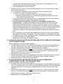
C. CONSIDERATIONS FOR BOILER LOCATION
Before selecting a location for the boiler, the following should be considered. Each boiler
considered.
• Supplied with the correct type of gas (natural gas or propane).
• Connected to a suitable combustion air intake piping system to supply the correct
amounts of fresh (outdoor) air for combustion. (maximum length 80' for the Model-100
boiler, and maximum length 100' for the Model-75 and Model-50 boilers).
• Connected to a suitable venting system to remove the hazardous products of gas
combustion (maximum length 80' for the Model-100 boiler, and maximum length 100' for
the Model-75 and Model-50 boilers).
• Connected to a suitable hot water heating system
• Supplied with a suitable electrical supply for all boiler motors and controls.
• Connected to a properly located thermostat or operating control. (not included with
boiler)
• Placed on level surface (must NOT be installed on carpeting)
• Condensate drain line must be pitched down to floor drain or external condensate
pump with reservoir at ¼" per foot (wood frame or blocks may be used to raise boiler).
8

9
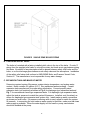
1. Select a location which is level, central to the piping systems served and as close to the
vent and air intake terminals as possible.
2. Accessibility clearances, if more stringent (i.e. larger clearances) than required fire protection
clearances, must be used for the boiler installation. Accessibility clearances may be achieved
with the use of removable walls or partitions.
3. The boiler is approved for installation in closets and on combustible floors. This boiler
shall NOT be installed on carpeting.
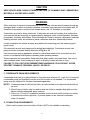
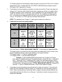
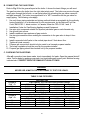
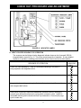
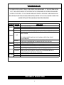
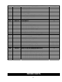
4. The clearances shown in Table 2 indicate required clearances per IAS listing. A minimum
1" clearance must be maintained between combustible construction and each of the left,
top and back surfaces of the boiler. A minimum 8" clearance is required on the right side,
to allow room for the inlet air pipe. An 18" clearance must be maintained at a side where
passage is required to access another side for cleaning or servicing, inspection or
replacement of any parts that normally may require such attention. Allow at least 24" at
the front and left side and 8" at the top for servicing. No clearances are required to
venting or combustion air intake piping.
5. Equipment shall be installed in a location which facilitates the operation of venting and
combustion air intake piping systems as described in this manual.
6. Advise owner of boiler to keep venting and combustion air intake passages free of obstructions.
both the venting and combustion air intake piping systems connected to the outdoors must
permit flow through the piping systems without restrictions for the boiler to operate.
7. The boiler shall be installed such that the automatic gas ignition system components are
protected from water (dripping, spraying, rain, etc.) during operation and service
(circulator replacement, control replacement, etc.).
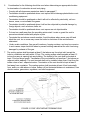
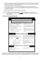
E. COMBUSTION AIR AND VENT PIPE REQUIREMENTS
This boiler requires a dedicated direct vent system. In a direct vent system, all air for
combustionis taken directly from outside atmosphere, and all flue products are discharged to
outside atmosphere.
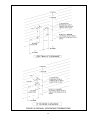
Combustion air and vent pipe connections must terminate together in the same atmospheric
pressure zone, either through the roof or sidewall (roof termination preferred). See Fig.9 & 10
for required clearances.
D. LOCATING THE BOILER
&20%86 7,%/( $&&(6 6,%,/,7<
&216758&7,21 &/($ 1,1*
723
/()76,'(
5, *+7 6,'(
%$6(
)5 21 7
%$&.
,17$.(9(173,3,1*
1($5%2, /(5+27:$7(5
:$7(53,3,1*
81,7
7$%/(
6(59,&,1*
%2,/(5&/($5$1&(6

10
CAUTION
KEEP BOILER AREA CLEAN OF DEBRIS AND FREE OF FLAMABLE AND COMBUSTIBLE
MATERIALS, VAPORS AND LIQUIDS
WARNING
When vent pipe is exposed to temperatures below freezing, such as when it passes through an
unheated space or when a chimney is used as a raceway, vent pipe must be insulated with 1/2
Armaflex or equivalent. In extreme cold climate areas, use
3
/4" Armaflex or equivalent.
Combustion air must be clean outdoor air. Combustion air must not be taken from inside struc-
ture because that air frequently is contaminated by halogens, which include fluorides, chlorides,
phosphates, bromides and iodides. These elements are found in aerosols, detergents, bleaches,
cleaning solvents, salts, air fresheners, paints, adhesives and other household products.
Locate combustion air inlet as far away as possible from swimming pool and swimming pool
pump house.
All combustion air and vent pipes must be airtight and watertight. Combustion air and vent
piping must also terminate exactly as shown in Fig.9 or 10.
Vent connections serving appliances vented by natural draft shall not be connected into any
portion of mechanical draft systems operating under positive pressure.
Solvent cements are combustible. Keep away from heat, sparks, and open flame. Use only in
well ventilated areas. Avoid breathing in vapor or allowing contact with skin or eyes.
FAILURE TO FOLLOW THE AFOREMENTIONED WARNINGS COULD RESULT IN FIRE,
PROPERTY DAMAGE, PERSONAL INJURY, OR DEATH.
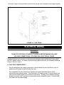
F. CONDENSATE DRAIN REQUIREMENTS
Condensate drain line to be pitched down to floor drain at a minimum of
1
/4" per foot. An external
condensate pump (not furnished) may be used if floor drain is not available. The condensate
pump must be designed for flue gas condensate application
NOTE:1. Condensate trap is built into the boiler, an external trap is not required and should not
be used.
2. Wood frame or blocks may be used to raise the boiler to maintain drain pitch or to be
above external condensate pump reservoir.
3. There is a 115 volt AC receptacle provided on the service switch junction box which
is located at the boiler right side, to provide power for an external condensate
pump (if needed).
G. FOUNDATION REQUIREMENTS
Boiler must be placed on level surface. Boiler is NOT to be installed on carpeting.

11
NOTE: 1. If boiler is not level condensate drain lines will not function properly. Adjustable
feet are located on the boiler to make up for minor surface irregularities or tilt.
2. Wood frame or blocks may be used to raise boiler to maintain drain pitch or to be
above external condensate pump reservoir.
H. REMOVAL OF EXISTING BOILER FROM COMMON VENT SYSTEM
When an existing boiler is removed from a common venting system, the common venting
system is likely to be too large for proper venting of the appliances remaining connected to it.
At the time of removal of an existing boiler, the following steps shall be followed with each
appliance remaining connected to the common venting system placed in operation, while the
other appliances remaining connected to the common venting system are not in operation.
1. Seal any unused openings in the common venting system.
2. Visually inspect the venting system for proper size and horizontal pitch and determine
there is no blockage. or restrictions, leakage, corrosion and other deficiencies which could
cause an unsafe condition.
3. Insofar as is practical, close all. building doors and windows and all doors between the
space in which the appliances remaining connected to the common venting system are
located and other spaces of the building. Turn on clothes dryer and any appliance not
connected to the common venting system. Turn on any exhaust fans, such as range
hoods and bathroom exhaust, so they will operate at maximum speed. Do not operate a
summer exhaust fan. Close fire dampers.
4. Place in operation the appliance being inspected. Follow the lighting instructions. Adjust
thermostat so appliances will operate continuously.
5. Test for spillage at the draft hood relief opening after 5 minutes of main burner operation.
Use the flame of a match or candle, or the smoke from a cigarette, cigar or pipe.
6. After it has been determined that each appliance remaining connected to the common venting
system properly vents when tested as outlined above, return doors, windows, exhaust fans
and any other gas-burning appliance to their previous condition of use.
7. Any improper operation of the common venting system should be corrected so the
installation conforms with the National Fuel Code, NFPA-54/ANSI -Z223.1-latest revision,
or section 5 of CSA-B 149 for Canadian standards. When resizing any portion of the
common venting system, the common venting system should be resized to approach the
minimum size as determined using the appropriate tables in part 11 in the National Fuel
Gas Code, NFPA-54/ANSI- Z223.1-latest revision, or section 5 of CSA-B 149 for
Canadian standards.
The boiler should be placed to provide the most direct connections to the combustion air, vent
and system piping as possible.
Place crated boiler as close to selected location as possible and uncrate boiler. The uncrated
boiler may be moved into position with an appliance dolly or 2-wheel hand truck. The dolly or hand
truck should be inserted under the left hand side of the boiler. It is possible to slide the boiler for a
short distance on a smooth floor or surface.
NOTE: Refer to manual section LOCATING THE BOILER for required clearances for servic
ing and maintenance.
PLACING THE BOILER

12
CAUTION
Copper supply and return piping. must NOT be installed directly into aluminum boiler section
casings due to galvanic corrosion between dissimilar metals. Iron or steel bushings or pipe
nipples should be used between copper system piping and boiler to make final connection to
boiler. Also, the use of dielectric unions is acceptable. The packaged boiler is furnished with iron
piping in the front boiler section for the supply and return connections.
When the installation of the boiler is for a new heating system, first install all of the radiation
units (panels, radiators, baseboard, or tubing) and the supply and return mains. After all heating
system piping and components have been installed, make final connection of the system piping
to the boiler. A hot water boiler installed above radiation level must be equipped with a low water
cut off device. A periodic inspection is necessary us is flushing of float type devices, per low
water cut off manufacturers specific instructions.
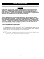
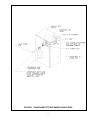
A. SUPPLY AND RETURN LINES
The packaged boiler unit is set up to receive 1
1/4" NPT supply and return piping from top
access. The boiler unit can also be piped from the left side by turning the supply elbow, and
from the rear of the unit by removing plugs in the rear boiler section.
NOTE: The circulator pump and isolation valves are furnished within a carton inside the boiler
cabinet and can be installed at the installer preferred location.
NEAR BOILER PIPING

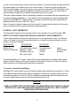
FIGURE 2 SINGLE ZONE BOILER PIPING
13

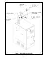
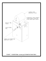
FIGURE 3 MULTI ZONE BOILER PIPING WITH ZONE VALVES
14

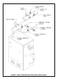
NOTE: When zoning with circulators, the furnished circulator pump should be used as one of the
zone pumps. Each stripped end of the electrical wires for the circulator pump inside the junction
box should be taped or wire nutted to prevent short circuits. Unplug the circulator pump wiring at
the integrated boiler control.
FIGURE 4 MULTI ZONE BOILER PIPING WITH CIRCULATORS
15

B. PRESSURE RELIEF VALVE
The boiler is furnished with a factory installed relief valve in the top of the boiler. Provide ¾
piping from the supplied relief valve to a local floor drain, but leave an air gap between piping
and drain. No shutoff of any description shall be placed between safety relief valve and the
boiler, or on the discharge pipes between such safety valve and the atmosphere. Installation
of the safety relief valve shall conform to ANSI/ASME Boiler and Pressure Vessel Code,
Section IV. The manufacturer is not responsible for any water damage.
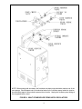
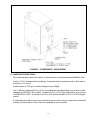
C. EXPANSION TANK AND MAKE-UP WATER
Determine required system fill pressure, system design temperature, and system water
content. Boiler contains 2.6 gallons (U.S.). Size expansion tank accordingly. Consult
expansion tank manufacturer for proper sizing information. Connect properly sized
expansion tank (not furnished) as shown in Fig. 6 for diaphragm type expansion tank and
Fig. 7 for conventional closed type expansion tanks. For diaphragm type expansion tanks,
adjust the tank air pressure to match the system fill pressure. Install air vent (furnished) as
shown for diaphragm type expansion tank system only. Install make-up water connections
as shown per local codes. If a pressure reducing valve is used, adjust to match the system
fill pressure. In connecting the cold make-up water supply to the boiler, make sure that clean
water supply is available. When the water supply is from a well or pump, sand strainer
should be installed at the pump.
16
FIGURE 5 SINGLE ZONE BOILER PIPING

FIGURE 6 DIAPHRAGM TYPE EXPANSION TANK PIPING
17

FIGURE 7 CONVENTIONAL (closed type) EXPANSION TANK PIPING
18
La pagina si sta caricando...
La pagina si sta caricando...
La pagina si sta caricando...
La pagina si sta caricando...
La pagina si sta caricando...
La pagina si sta caricando...
La pagina si sta caricando...
La pagina si sta caricando...
La pagina si sta caricando...
La pagina si sta caricando...
La pagina si sta caricando...
La pagina si sta caricando...
La pagina si sta caricando...
La pagina si sta caricando...
La pagina si sta caricando...
La pagina si sta caricando...
La pagina si sta caricando...
La pagina si sta caricando...
La pagina si sta caricando...
La pagina si sta caricando...
La pagina si sta caricando...
La pagina si sta caricando...
La pagina si sta caricando...
La pagina si sta caricando...
La pagina si sta caricando...
La pagina si sta caricando...
La pagina si sta caricando...
La pagina si sta caricando...
La pagina si sta caricando...
La pagina si sta caricando...
La pagina si sta caricando...
La pagina si sta caricando...
La pagina si sta caricando...
La pagina si sta caricando...
La pagina si sta caricando...
La pagina si sta caricando...
La pagina si sta caricando...
La pagina si sta caricando...
La pagina si sta caricando...
La pagina si sta caricando...
La pagina si sta caricando...
La pagina si sta caricando...
La pagina si sta caricando...
La pagina si sta caricando...
La pagina si sta caricando...
La pagina si sta caricando...
La pagina si sta caricando...
La pagina si sta caricando...
-
 1
1
-
 2
2
-
 3
3
-
 4
4
-
 5
5
-
 6
6
-
 7
7
-
 8
8
-
 9
9
-
 10
10
-
 11
11
-
 12
12
-
 13
13
-
 14
14
-
 15
15
-
 16
16
-
 17
17
-
 18
18
-
 19
19
-
 20
20
-
 21
21
-
 22
22
-
 23
23
-
 24
24
-
 25
25
-
 26
26
-
 27
27
-
 28
28
-
 29
29
-
 30
30
-
 31
31
-
 32
32
-
 33
33
-
 34
34
-
 35
35
-
 36
36
-
 37
37
-
 38
38
-
 39
39
-
 40
40
-
 41
41
-
 42
42
-
 43
43
-
 44
44
-
 45
45
-
 46
46
-
 47
47
-
 48
48
-
 49
49
-
 50
50
-
 51
51
-
 52
52
-
 53
53
-
 54
54
-
 55
55
-
 56
56
-
 57
57
-
 58
58
-
 59
59
-
 60
60
-
 61
61
-
 62
62
-
 63
63
-
 64
64
-
 65
65
-
 66
66
-
 67
67
-
 68
68


Quantum GAS-FIRED BOILERS Manuale utente
- Categoria
- Scaldabagno
- Tipo
- Manuale utente
- Questo manuale è adatto anche per
in altre lingue
Altri documenti
-
Gorenje TC100ZNT Manuale del proprietario
-
Bosch HGS8055UC Guida d'installazione
-
-
Bosch HDS8645U Guida d'installazione
-
Little GIANT APCP-1700 Manuale del proprietario
-
kozy heat #511 Manuale del proprietario
-
Calorex C-PAC+ Guida d'installazione
-
-
-
elco THISION L EVO Operation and Maintenance Manual