elco THISION L EVO Operation and Maintenance Manual
- Tipo
- Operation and Maintenance Manual

Installaon and Operaon manual
for authorised technicians only
THISION L EVO
10-2018 420010585004

4
EN
Contents
GENERAL REGULATIONS ................ 5
Applicaon ..................................... 5
Norms and regulaons ................... 5
Informaon for installer and mainte-
nance service personnel ................. 6
Data Plate ....................................... 7
CONSTRUCTION ............................. 8
Layout of the boiler ........................ 8
Operang principle ......................... 8
TECHNICAL DATA ............................ 9
Product informaon E.r.P. ............... 10
Dimensions ..................................... 12
EXTENT OF DELIVERY ..................... 13
Standard boiler ............................... 13
Accessories ..................................... 13
INSTALLATION ................................ 14
Boiler transport .............................. 14
Removing the casing ...................... 14
Warnings before installaon .......... 15
Boiler installaon............................ 15
Connecng the boiler ..................... 16
Outside sensor mounng ............... 17
Air/Flue gas system ........................ 17
Air/Flue gas connecons ................ 17
Air/Flue gas data ............................ 18
Air/Flue gas system-dimensioning .. 20
Accessories ..................................... 21
Installaon instrucons .................. 22
-Coaxial pipe .................................. 22
-Twin pipe ...................................... 23
-Vercal ue terminal .................... 24
-Horizontal ue terminal ............... 25
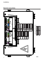
Wiring diagram - Legend ................ 26
Wiring diagram - Boiler .................. 27
COMMISSIONING........................... 28
Hydraulic system ............................ 28
Neutralisaon systems ................... 29
Gas supply ...................................... 30
Condensate connecon .................. 30
Flue and air intake connecons ...... 30
Prepare boiler for rst startup ........ 31
Combuson analysis ....................... 32
Combuson sengs ....................... 32
Check water ow ............................ 33
Check safety devices ....................... 34
Gas ghtness check ........................ 34
Boiler shut down ............................ 34
Commissioning protocol ................. 35
OPERATING INSTRUCTIONS ........... 36
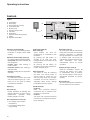
Controls .......................................... 36
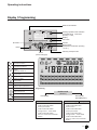
Display / Programming ................... 37
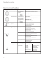
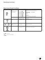
Overview of main funcons ........... 38
MAINTENANCE .............................. 40
Checklist ......................................... 40
Replacing the electrodes ................ 40
Cleaning condensate receptacle ..... 41
Cleaning and relling the syphon ... 41
Inspecon of combuson chamber 41
Physical and chemical check ........... 42
Maintenance Checklist ................... 43
LOCKOUTS ...................................... 44
SENSOR VALUES ............................. 46
DECLARATION OF CONFORMITY ... 47
NOTE .............................................. 48

5
General Regulaons
EN
Applicaon
Norms and regulaons
This boiler is CE approved and applies
to the following European standards:
• 1992/42/EEC Boiler eciency di-
recve.
• 2016/426/EEC Gas appliances reg-
ulaon.
• 2009/125/EC Direcve of the
European Parliament and of the
Council of 21 October 2009 estab-
lishing a framework for the seng
of ecodesign requirements for en-
ergy-related products.
• 811-813-814/2013 EU regulaon.
• 2014 / 30 / EU The Electromag-
nec Compability (EMC) Direc-
ve.
• 2014 / 35 / EU Low Voltage Direc-
ve.
• EN 13203-2: 2015 (Gas-red do-
mesc appliances producing hot
water - Part 2: Assessment of en-
ergy consumpon).
• EN 15036-1: 2006 Heang boilers -
Test regulaons for airborne noise
emissions from heat generators
- Part 1: Airborne noise emissions
from heat generators.
• EN-ISO 3743-1: 2010 Acouscs
- Determinaon of sound power
levels and sound energy levels of
noise sources using sound pres-
sure - Engineering methods for
small movable sources in rever-
berant elds - Part 1: Comparison
method for a hard-walled test
room.
• EN 15502-1: 2012 +A1:2015 (Gas-
red heang boilers - Part 1: Gen-
eral requirements and tests).
• EN 15502-2-1: 2012 (Gas-red
central heang boilers - Part 2-1:
Specic standard for type C appli-
ances and type B2, B3 and B5 ap-
pliances of a nominal heat input
not exceeding 1000 kW).
• EN 60335-1 Household and similar
electrical appliances - Safety- Part
1: General requirements.
• EN 60335-2-102: 2016 Household
and similar appliances - Safety
- Part 2-102: Parcular require-
ments for gas, oil and solid-fuel
burning appliances having electri-
cal connecons.
• EN 55014-1: 2006 Electromag-
nec compability- Requirements
for household appliances, electric
tools and similar apparatus Part 1:
Emission A1:2009, A2:2011.
• EN 55014-2: 2015 Electromag-
nec compability- Requirements
for household appliances, electric
tools and similar apparatus Part 2:
Immunity - Product family stand-
ard.
• EN 61000-3-2: 2014 Electromag-
nec compability (EMC) Part 3-2:
Limits — Limits for harmonic cur-
rent emissions equipment input
current ≤ 16 A per phase.
• EN 61000-3-3: 2013 Electromag-
nec compability (EMC) Part
3-3: Limits — Limitaon of voltage
changes, voltage uctuaons and
icker in public low-voltage supply
systems, for equipment with rated
current ≤ 16 A per phase and not
subject to condional connecon.
Addional naonal standards
Germany:
• RAL - UZ 61 / DIN 4702-8
Switzerland:
• SVGW
Austria:
• 15a V-BG
This documentaon contains
important informaon, which
is a base for safe and reliable
installaon, commissioning and op-
eraon of the THISION L EVO boiler.
All acvies described in this docu-
ment may only be excecuted by au-
thorized companies.
Changes to this document may be
eected without prior noce. We
accept no obligaon to adapt previ-
ously delivered products to incorpo-
rate such changes.
Only original spare parts may be
used when replacing components
on the boiler, otherwise warranty
will be void.
Applicaon
The boiler may be used for heang
and hot water producon purposes
only. The boiler should be connect-
ed to closed systems with a maxi-
mum temperature of 100°C (high
limit temperature), maximum set-
point temperature is 90°C.
Norms and regulaons
When installing and operang the
boiler, all applicable norms (euro-
pean and local) should be fullled:
• Local building regulaons for in-
stalling combuson air and ue
gas systems;
• Regulaon for connecng the boil-
er to the electrical appliance;
• Regulaons for connecng the
boiler to the local gas network;
• Norms and regulaons according
to safety equipment for heang
systems;
• Any addional local laws/regula-
ons with regard to installing and
operang heang systems.

6
General Regulaons
Informaon for installer and maintenance service personnel
The use of the appliance for
purposes other than those
specied is strictly forbidden.
The manufacturer cannot be held
responsible for any damage caused
by improper, incorrect and unrea-
sonable use of the appliance or by
the failure to comply with the in-
strucons given in this manual.
Installaon, maintenance and
all other intervenons must be
carried out in full conformity
with the governing legal regulaons
and the instrucons provided by the
manufacturer. Incorrect installaon
can harm persons, animals and pos-
sessions; the manufacturing com-
pany shall not be held responsible
for any damage caused as a result.
The boiler is delivered with
protecon packaging.
Once you have removed all the
packaging, make sure the appliance
is intact and that no parts are miss-
ing. If this is not the case, please
contact your supplier.
Keep all packaging material
(clips, plasc bags, polysty-
rene foam, etc.) out of reach of
children as it may present a poten-
al hazard.
Before any maintenance or
repair work is performed on
the boiler, make sure you have
disconnected it from the electric-
ity supply by switching the external
double pole isolator to the OFF po-
sion.
All repairs, should only be per-
formed using original spare
parts.
Index:
Risk of damage for the boiler
Risk of injury
Informaon for the User
Inform the user about the mode of
operaon of the system. Specically
deliver to the user the instrucon
manuals, informing him that they
must be stored with the appliance.
Also, remind the user to:
• Periodically check the water pres-
sure system and instruct him on
how to reintegrate and bleed.
.
• How to set the temperature and
the adjusters for a correct and
more economical management of
the system.
• To perform, according to legis-
laon, periodic maintenance
system.
• Do not change, in any case, the
sengs for supply of air for com-
buson and gas combuson.
• Pay aenon to the warnings
contained in the user manual.
This appliance can be used by children aged from 8 years
and above and persons with reduced physical, sensory or
mental capabilies or lack of experience and knowledge
if they have been given supervision or instrucon con-
cerning use of the appliance in a safe way and under-
stand the hazards involved children shall not play with
the appliance. Cleaning and user maintenance shall not
be made by children without supervision.
This product conforms to
Direcve
WEEE 2012/19/EU.
The symbol of the crossed waste
paper basket on the appliance
indicates that at the end of its
working life the product should be
disposed of separately from normal
domesc household rubbish, it must
be disposed of at a waste disposal
centre with dedicated facilies for
electric and electronic appliances or
returned to the retailer when a new
replacement product is purchased.
The user is responsible for the
disposal of the product at the end
of its life at an appropriate waste
disposal centre.
The waste disposal centre (which
using special treatment and recycling
processes eecvely dismantles and
disposes of the appliance) helps to
protect the environment by recycling
the material from which the product
is made.
For further informaon about
waste disposal systems visit your
local waste disposal centre or the
retailer from which the product was
purchased.

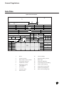
Symbols used on the data plate
Legend :
1 Brand
2
Country of origin
3 Boiler model - Serial number
4 Commercial reference
5 Certication number
6 Destination country - Gas category
7 Gas setting
8 Installation type
9 Electrical data
10 Factory settings
11 Maximum water pressure
12 Boiler type
13 NOx class / Efciency
14 Input rating nominal heating
15 Power output heating
16 Gases which may be used
17 Ambient operating temperature
18 Max. central heating temperature
26-05-2015
S/N 0000000KE000000000000
00
100% min.
η η
= =
MAX MIN
Q(Hi)
P
P
60/80C
30/50C
gas
mbar
gas
mbar
gas
mbar
0000000KE000000000000
0000000KE000000000000
0000000KE000000000000
6
0000000KE000000000000
5
0000000KE000000000000
4
0000000KE000000000000
3
0000000KE000000000000
2
0000000KE000000000000
1
PCT
0000000 KE 000000000000
26-5-2015 13:07:34
1
2
3
4
5
6
7
8
9
10
11
12
13
14
15
16
17
18
General regulations
Data plate
7
General Regulaons
EN
Symbols used on the data plate
1 Brand
2
Country of origin
3 Boiler model - Serial number
4 Commercial reference
5 Cercaon number
6
Desnaon country
- Gas category
7 Gas seng
8 Installaon type
9 Electrical data
10 Factory sengs
11 Maximum water pressure
12 Boiler type
13 NOx class / Eciency
14 Input rang nominal heang
15 Power output heang
16 Gases which may be used
17 Ambient operang temp.
18 Max. central heang temp.
Data Plate

4
3
1
2
11
6
7
9
8
10
5
16
12
18
17
14
13
15
Construcon
8
Operang principle
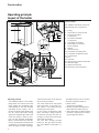
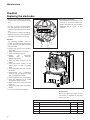
Layout of the boiler
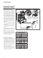
Layout of boiler
The THISION L EVO boiler consists of
the following main components:
1. Casing
2. Access door to control panel
3. Flue gas connecon
(+ test point)
4. Air intake connecon
(+ test point)
5. Flow water connecon
6. Return water connecon
7. Gas connecon
8. Syphon
9. Input for wiring
10. Connecon for safety valve
11. Connecon for ll/drain valve
12. Control Panel
13. Fan
14. Gas valve
15. Ignion and ionisaon electrodes
16. Heat exchanger
17. Ignion transformer
18. Electrical input connecons
Operang principle
The THISION L EVO is a fully modu-
lang boiler. The control unit of the
boiler adapts the modulaon rao
automacally to the heat demand
requested by the system. This is
done by controlling the speed of the
fan. As a result, the venturi mixing
system will adapt the gas rao to the
chosen fan speed, in order to main-
tain the best possible combuson
gures and therewith the best e-
ciency. The ue gases created by the
combuson are transported down-
wards through the heat exchanger
and leave the boiler at the top into
the chimney connecon.
The return water from the system
enters the boiler in the lower sec-
on, where is the lowest ue gas
temperature in the boiler.
In this secon condensaon takes
place. The water is being transport-
ed upwards through the heat ex-
changer, in order to leave the boiler
at the ow connecon.
The cross ow working principle
(water up, ue gas down) ensures
the most ecient combuson re-
sults.
The LMS14 control unit can control
the boiler operaon based on:
• Boiler control
(stand alone operaon);
• weather compensated operaon
(with oponal outdoor sensor);
• with 0-10V external inuence (tem-
perature or capacity) from a build-
ing management system.

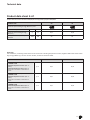
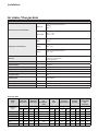
Technical data
EN
9
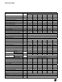
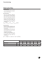
THISION L EVO
60 70 80 100 120 140
Nominal heat output at 80/60°C max/min
kW 56,5/15,5 65,5/15,6 75,3/19,4 92,9/18,7 111,9/22,5 130,4/26,2
Nominal heat output at 50/30°C max/min kW 60,4/17,2 70,0/17,2 79,7/21,2 98,9/20,6 118,5/24,8 137,8/28,9
Nominal heat output at 40/30°C max/min
kW 60,5/17,3 70,0/ 17,4 79,7/21,5 98,9/20,9 118,5/25,2 137,8/29,3
Nominal heat input Hi max/min kW 57,9/16,0 66,8/16,0 76,8/19,8 95,2/19,0 114,3/22,9 133,3/26,7
Modulaon rao - 3,6 4,2 3,9 5,0 5,0 5,0
Eciency at 80/60°C max/min
% 97,6/97,0 98,0/97,5 98,0/97,9 97,6/98,3 97,9/ 98,3 97,8/ 98,3
Eciency at 50/30°C max/min
% 104,4/107,4 104,8/107,3 103,8/107,2 103,9/108,5 103,7/108,4 103,4/108,3
Eciency at 40/30°C max/min
% 104,5/108,3 104,8/108,5 103,8/108,6 103,9/110,0 103,7/109,9 103,4/109,8
Eciency at 36/30°C load 30%
% 107,2 107,2 107,1 107,8 107,9 107,6
RAL 40/30 average
% 108,7 109,1 109,4 109,4 109,1 108,7
Heat Loss (Pstby) W 81,0 81,0 81,0 92,7 92,7 92,7
Max. condensate ow l/h 3,6 4,4 4,3 5,4 6,4 7,1
Gas consumpon G20 max/min (10,9 kWh/m
3
)
m
3
/h 5,3/1,5 6,1/1,5 7,0/1,8 8,7/1,7 10,5/2,1 12,2/2,4
Gas consumpon G25 max/min (8,34 kWh/m
3
)
m
3
/h 6,9/1,9 8,0/1,9 9,2/2,4 11,4/2,3 13,7/2,7 16,0/3,2
Gas consumpon G31 max/min (12,8 kWh/kg)
kg/h 4,5/1,3 5,2/1,3 6,0/1,5 7,4/1,5 8,9/1,8 10,4/2,1
Gas pressure G20
mbar 20
Gas pressure G25
mbar 25
Gas pressure G31 mbar 30/50
Maximum gas pressure
mbar 50
Max. temperature ue gas (high limit)
°C 90
Flue gas temperature at 80/60°C max/min
°C 59/57 60/57 61/58 60/56 63/56 66/57
Flue gas temperature at 50/30°C max/min
°C 43/35 44/34 45/33 44/33 46/33 48/33
Flue gas temperature at 40/30°C max/min
°C 42/33 44/33 44/33 43/32 45/32 47/32
Flue gas temperature at 36/30°C load 30%
°C 34 35 35 33 34 35
Flue gas quanty max/min
m
3
/h 83/22 98/22 113/27 139/27 168/33 202/38
CO level at 80/60 °C max/min
ppm 75/11 92/11 87/7 67/5 82/4 62/7
CO level at 80/60 °C max/min
mg/kWh 80/11 99/11 94/7 72/5 88/5 67/7
CO year emission EN15502
ppm 35,79 43,76 51,73 41,53 40,76 39,99
CO year emission EN15502
mg/kWh 38,44 47,00 55,56 44,60 43,78 42,95
CO
2
level G20-G25
Max. load
%
8,5 (+0 -0,2) 8,4 (+0 -0,2) 8,4 (+0 -0,2) 8,4 (+0 -0,2) 8,4 (+0 -0,2) 8,2 (+0 -0,2)
Min. load
9,0 (+0 -0,2) 9,0 (+0 -0,2) 9,0 (+0 -0,2) 8,5 (+0 -0,2) 8,5 (+0 -0,2) 8,5 (+0 -0,2)
Restricon ΔCO2 max.load - min. load (G20-G25) % - - - - - <0,3
CO
2
level G31
Max. load
%
9,6 (0 +0,2)
Min. load
9,6 (0 +0,2)
Restricon ΔCO2 max.load - min. load (G31) % CO
2 Min. load ≤ CO2 Max. load
NO
x
level at 80/60 °C max/min
ppm 25/10 30/11 34/16 25/11 22/15 15/15
NO
x
level at 80/60 °C max/min
mg/kWh 44/17 53/19 60/28 44/19 38/27 26/26
NOx emission EN15502 (ppm)
ppm 13,94 18,78 23,61 28,38 22,61 16,84
NOx emission Hi/Hs EN15502 (mg/kWh)
mg/kWh 24,60/22,15 32,61/29,36 40,61/36,57 46,67/42,03 38,19/34,40 29,71/26,76
NOx class EN15502
6
Max. permissible ue resistance
Pa 167 200 200 173 134 200
Water volume l 6 6 6 9 9 9
Water pressure max/min
bar 8/1 8/1 8/1 8/1 8/1 8/1
Max. water temperature
(High limit thermostat)
°C 100 100 100 100 100 100
Maximum temperature setpoint
°C 90 90 90 90 90 90
Nominal water ow at dT=20 K m
3
/h 2,4 2,8 3,2 4,0 4,8 5,6
Hydraulic resistance at nominal ow rate kPa 15 18 22 7 9 11
Electrical connecon
V 230
Frequency
Hz 50
Mains connecon fuse
A 10
IP class with Appliance Type B23(P) - IP30

Technical data
10
Product informaon E.r.P.
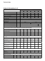
THISION L EVO
60 70 80 100 120 140
IP class with App. Type
C13, C33, C43, C53, C63, C83,
-
IPX4D
Weight (empty) Kg 83 83 83 96 96 96
Weight (lled with water) Kg 89 89 89 105 105 105
Sound Power Level (LWA) dB 55 55 56 62 57 57
Ionisaon current μA 1,15 1,15 1,15 4,2 1,15 4,2
Rpm max / min load G20-G25 rpm 6070/1770 7260/1800 7820/2060 6710/1570 6000/1370 5730/1300
Rpm max / min load G31 rpm 5810/1770 6710/1800 7190/2060 6090/1570 6000/1370 5460/1300
Rpm pre / post purge rpm 2800/2800
pre / post purge me sec 10/30
safety me sec 5
pH value condensate - 3,2
CE cercaon code
- CE-0063CM3576
Water connecons
- R1.1/4” R1.1/2”
Gas connecon
- R3/4” R1”
Flue gas connecon (DN)
- 100 130
Air intake connect
(room sealed use)
(DN)
mm 100 130
Condensate connecon
mm 22
Product informaons about the direcve 2009/125/EG and regulaon (EU) 811-813/2013
THISON L EVO
ICON
60 70 80 100 120 140
Condensing boiler
-
Yes Yes Yes Yes Yes Yes
Low-temperature boiler
-
No No No No No No
B1 boiler
-
No No No No No No
Cogeneraon space heater
-
No No No No No No
Combinaon heater
-
No No No No No No
ErP Heang 1) by return temperature 30°C 2) by return temperature and feed temperature (60-80°C)
Rated heat boiler
P
rated
kW
57 66 75 93 112 130
At rated heat output and high-tem-
perature regime
P4 kW 56,5 65,5 75,3 92,9 111,9 130,4
At 30 % of rated heat output and
lowtemperature regime 1)
P1 kW 18,6 21,5 24,7 30,8 37,0 43,0
Seasonal space heang energy
eciency
hs % 91,7 91,8 91,7 92,3 92,5 92,3
At rated heat output and high-tem-
perature regime 2)
h4 % 87,9 88,2 88,2 87,9 88,2 88,1
At 30 % of rated heat output and low
temperature regime 1)
h1 % 96,5 96,5 96,4 97,1 97,2 96,9
Auxiliary electricity consumpon
At full load
elmax kW 0,10 0,12 0,13 0,13 0,12 0,15
At 30% load el30% kW 0,03 0,03 0,04 0,03 0,04 0,03
In stand-by mode PSB kW 0,004
Supplementary heater
Standby heat loss Pstby kW 0,081 0,093
Ignion burner power consumpon Pign kW NA NA NA NA NA NA
Emissions of nitrogen oxides NOX mg/kWh
22 29 37 42 35 27

Technical data
EN
11
Product data sheet E.r.P.
Product data about the direcve 2010/30/EU and regulaon (EU) 811-813/2013
THISON L EVO 60 70
Seasonal space heang energy eciency class
8
Important:
The installation, consi ting of the boiler and all ac es ories including temperature control, together define the seasonal
heating energy efficiency ηs for the various models, as listed in the below table.
Product data sheet ErP
www.elco.net
THISION L
THISION L 50 65 85 100 120 145
Class VI, with use of components:
- THISION L
- Ambient temperature sensor QAA 75
(option)
- External temperature sensor QAC 34
Temperature controller contribution to
ηs: 4%
η
%
92 + 4
=96
92 + 4
=96
92 + 4
=96
92 + 4
=96
92 + 4
=96
92 + 4
=96
Class V, with use of components:
- THISION L
- Ambient temperature sensor QAA 75
(option)
Temperature controller contribution to
ηs: 3%
η %
92 + 3
=95
92 + 3
=95
92 + 3
=95
92 + 3
=95
92 + 3
=95
92 + 3
=95
Class II, with use of components:
- THISION L
- External temperature sensor QAC 34
Temperature controller contribution to
ηs: 3%
η
%
92 + 3
=95
92 + 3
=95
92+ 3
=95
92+ 3
=95
92+ 3
=95
92+ 3
=95
Product data about the directive 2010/30/EU and regulation (EU) 813/2013
THISION L 50 65 85 100 120 145
Seasonal space heating energy efficiency class
Rated heat output P
rated
kW
46 61 81 93 112 132
Annual energy consumption QHE kWh 0 0 0 0 0 0
Seasonal spa e heating energ
efficien
η
%
92 92 92 92 92 92
Sound power level, indoors/ outdoor LWA dB
62 62 66 66 68 67
A
A
A
A
A
A
Rated heat output
Prated
kW
57 66
Seasonal space heang energy
eciency
hs
% 91,7 91,8
Sound power level, indoors/
outdoors
LWA
dB 55 55
Important:
The installaon, consisng of the boiler and all accessories including temperature control, together dene the seasonal hea-
ng energy eciency hs for the various models, as listed in the below table.
THISON L EVO 60 70
Class VI, with use of components:
-
THISON L EVO
- Ambient temperature sensor QAA 75
(opon)
- External temperature sensor QAC 34
Temperature controller contribuon to
hs: 4%
hs %
95,7 95,8
Class V, with use of components:
-
THISON L EVO
- Ambient temperature sensor QAA 75
(opon)
Temperature controller contribuon to
hs: 3%
hs %
94,7 94,8
Class II, with use of components:
-
THISON L EVO
- External temperature sensor QAC 34
Temperature controller contribuon to
hs: 2%
hs %
93,7 93,8

100L
B
85
H
87
162162
81
180
A
F
W1 W2
G
M
215
D
74
154
638
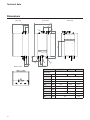
Technical data
12
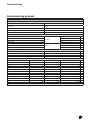
Model 60/70/80 100/120 140
Dim/Type
A mm
100 100 130
B mm
630
D mm
605
H mm
810 950 950
W1 mm
R1.¼ R1.½ R1.½
W2 mm
R1.¼ R1.½ R1.½
G mm
R¾
R1 R1
F mm
100 100 130
L
mm
140 190
M
mm
115 130
Side view
Boom view
Front view Back view
Dimensions

EN
13
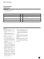
Extent of delivery
Standard boiler
A boiler delivery package contains
the following components:
Component Pcs. Package
Boiler fully assembled and tested 1 Cardboard box on pallet
Mounng bracket incl. mounng xings 1 Together with manuals, in carton inside
boiler packaging
Syphon for condensate connecon 1 Inside boiler packaging
Operaon and Installaon manual 1 Envelope packed in cardboard box in boiler packaging
Standard boiler
Accessories
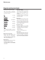
Accessories
Addional to the boiler, the following
accessories can be ordered:
• Speed controlled pump incl. connec-
on kit;
• Safety valve, ll/drain valve and con-
necon for expansion tank;
• Set with water (2x) and gas (1x)
cocks;
• Gas lter incl. connecon kit;
• Min. gas pressure switch;
• Plate heat exchanger (dT=10K/15K
or dT=20K) incl. connecon kit;
• Low velocity header, suitable for
dT=10K/15K and dT=20K incl. con-
necon kit;
• Plug & play cascade kit (see cascade
manual for more details);
• Extension module AGU2.551 for
0-10V control of a modulang pump
and/or boiler capacity feedback to
abuilding management system;
• Electrical connecon for external
gas valve and/or room fan;
• Extension module AGU2.550 for
heang zone control or external gas
valve and/or room fan control in
combinaon with an alarm signal;
For each boiler a maximum of 3
AGU2.550 modules (2x heang
zone, 1x ext. gas valve / room fan in
combinaon with alarm) can be in-
tegrated in the boiler;
• Addional RVS63 heang zone con-
troller, when controlling more than
2 zones (incl. wall hung box, all nec-
essary sensors and sockets and con-
necon material for bus communi-
caon).
The above accessories are specially
designed for the THISION L EVO boiler
and therewith easy to install (plug
and play).
By choosing a combinaon of the kits
menoned above, you can create
your own complete system soluon.
Ask your supplier for more detailed
informaon.

3
1
2
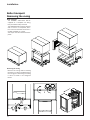
Installaon
14
Boiler transport
Removing the casing
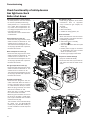
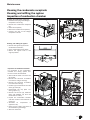
Removing the casing
Remove the casing before installing
the boiler, in order to avoid damage to
the casing parts. Removing the casing
is done as shown in the diagrams
below.
Boiler transport
The THISION L EVO boiler will be
supplied as a complete unit being
fully assembled and pre-tested.
The THISION L EVO can be transported
with a crane or a transpallet, but it
has to be ensured that the boiler is
packed and xed on a pallet.
The straps must be connected to the
pallet.

Installaon
EN
15
Warnings before installaon
Boiler installaon
Installaon, rst ignion, maintenance and boiler repair, must only be carried
out by qualied persons.
Before installing the appliance
Before connecng the boiler, it
is rst necessary to perform the
following operaons:
• Thoroughly cleanse and ush
the system pipework in order
to remove any installaon de-
bris;
• Make sure that the boiler is
suitable for operaon with the
type of gas available (read the
informaon on the packaging
label and on the boiler data
plate);
• Make sure that there are no
obstrucons inside ue system
and that it does not contain
any discharge from other ap-
pliances, unless the ue is de-
signed to as a cascade system
serving mulple boilers;
• If connecng the boiler to an ex-
isng ue, check to make sure
that it is sound and is construct-
ed using suitable materials/com-
ponents (suitable for use with
over-pressure design gas red
condensing boilers);
• The system water must be dosed
with a good quality water treat-
ment to prevent deposion of
scale within the boiler compo-
nents and to inhibit corrosion
within the system;
• In the event of installaon on a
wall constructed of combusble
material (e.g. wood) make sure
to protect the wall by suitable
insulaon.
WARNING!
No inammable items should be le
near the boiler.
If dust and/or aggressive vapours are
present in the room in which it is to
be installed, the appliance must be in-
stalled room sealed.
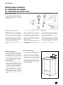
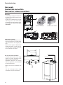
Boiler installaon
The boiler should be posioned in
a frost-free boiler room. When po-
sioning the boiler, please note the
recommended minimum clearance
in the diagram. When the boiler
is posioned with less free space,
maintenance acvies will be more
dicult.

3 1 5 6 2 4
8
7
9
Installaon
16
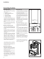
Connecng the boiler
Connecng the boiler
This chapter will explain how to
make all connecons to the boiler
with regard to:
• Hydraulic connecons
• Condensate drain connecon
• Gas connecon
• Flue gas connecon
• Air intake connecon
• Electrical connecon
The boiler should always be con-
nected in such a way, that the system
applies to all relevant standards and
regulaons (European, naonal and
local).
It’s the responsibility of the installer
to ensure that all standards and reg-
ulaons are respected.
Hydraulic connecons (1,2,3,4)
The boiler should always be con-
nected in such a way, that water ow
through the boiler can be ensured at
all mes.
Connect the ow (1) and return (2)
connecon of the system without
applying undue strain to the boiler
connecons.
The boiler contains a connecon
possibility for an (oponal) kit with
safety valve, ll/drain valve and an
expansion vessel connecon. The
safety valve must be connected to
the ow connecon (3) of the boiler,
the ll/drain valve and expansion
vessel connecon must be connect-
ed to the return connecon (4).
The (oponal) pump kit should be
mounted directly to the return con-
necon (2) of the boiler, before con-
necng to the system.
Condensate connecon (5)
Aer lling with water, the syphon
(included in delivery) should be in-
stalled to the connecon (5) at the
boom of the boiler.
Connect the hose to the draining sys-
tem in the boiler room.
The connecon to the draining sys-
tem should always be done with an
open connecon, in order to avoid
a ooding of the boiler in case of a
blocked drain.
Gas connecon (6)
The gas connecon must be made by
an authorized installer in accordance
with the applicable naonal and local
standards and regulaons.
Connect the gas line from the system
without applying undue strain to the
gas connecon (6) of the boiler. A gas
tap should be mounted directly be-
low the boiler.
ATTENTION: The Boiler is set for
G20-G25 gas type. To operate with
G31 gas type follow the procedures
described on page 30.
Electrical connecon
The electrical connecon must be
made by an authorized installer in
accordance with the applicable na-
onal and local standards and regu-
laons.
For the power supply it’s necessary
to use a mains isolator switch with
a contact opening of at least 3 mm
within the boiler room (according to
clause 22.3 of the EN-IEC-60335-1).
This switch can be used to switch o
the power supply for maintenance
purposes.
The boiler must be connected with a
power cord type H05V2V2-F.
All cables should be lead through the
cable glands (7 - 9) at the boom of
the boiler into the electro panel (8).
Connect all wires to the terminals ac-
cording to the wiring diagram of the
boiler, see pages 25-26.

8
7
Installaon
EN
17
Outside sensor mounng
Air intake/Flue gas system
Air intake/Flue gas connecons
Flue gas connecon (7)
Connect the ue gas system to the
ue gas connecon (7) of the boiler,
use uegas systems with seamless
connecons only. It’s not necessary
to make a separate condensate drain
for the ue gas system, as the con-
densate will be drained via the sy-
phon of the boiler.
Please note the following points:
• The diameter of the ue gas system
must be chosen by calculaon ac-
cording to the naonal regulaons;
• Construct the ue gas system as
short as possible (for maximum
length see planner documentaon);
• Horizontal ue secons must slope
of not less than 3° back towards the
boiler.
Air intake connecon (8)
The air intake can be connected in
case of room sealed installaon. The
diameter should be calculated ac-
cording to the naonal regulaons,
together with the ue gas system.
The total resistance of both systems
should never overcome the maxi-
mum permissible resistance of the
fan inside the boiler (see also chap-
ter: Technical data).
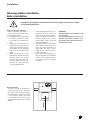
Outside sensor mounng
If an outside sensor (accessory) is
connected to the boiler, the sensor
should be posioned as shown on
the drawing.
Requirements and regulaons
Regulaons for the construcon of
ue gas systems are very dierent
for each country. It should be en-
sured that all naonal regulaons
with regard to ue gas systems are
respected. Pay aenon to the fol-
lowing recommendaons when di-
mensioning a ue gas system.
Only approved ue gas material may
be used.
The ue gas system must be
properly calculated to ensure a
safe funconing of the system.
Flue gas system components should
be removable for maintenance pur-
poses. Horizontal ue secons must
slope of not less than 3° back to-
wards the boiler.
This Boiler is cered for the ue gas
systems B23(P), C13, C33, C43, C53,
C63 and C83.
Materials
Only materials, which are heat re-
sistant and resistant to ue gases
and aggressive condensate, and CE
approved may be used.
Exclusively ue material as laid down
in the Elco catalogue may be used.
Please contact the local ELCO oce
for more informaon, at least for
conguraons C13, C33, C53.

Installaon
18
Air intake / Flue gas data
Air / Flue pipe data
Concentric pipe nominal diam.
Ø80/125
Tolerance female Ø internal
80,5
125
Ø100/150
Tolerance female Ø internal
101 mm
150 mm
Single pipe nominal diam.
Ø80
Tolerance female Ø internal
80,5
Ø100
Tolerance female Ø internal
101
±0.7
mm
Ø130
Tolerance female Ø internal
131
±0.7
mm
Material
PP (Concentric ue pipe) - Galva 0,4/Alluminium 1,3mm (Con-
centric air intake pipe)
PP (single pipe)
Material seal
EPDM black for corrosion class 1 / Viton for corrosion class 2
Heat resistance
0 W/m
2
K
Wall thickness
2.2 mm
Temperature class:
T120
Pressure class:
P1 max. 200Pa / H1 max. 5000Pa
Corrosion class:
W1
Locaon class
Concentric pipe: Only outside buildings / Single pipe: Only insi-
de buildings
Fire rang class
E
Outer wall class
(Concentric pipe only) L0
Distance to combusble materials
Concentric pipe: 00 mm / Single pipe: 30 mm
+1.0
- 0.5
+1.0
- 0.5
+1.0
- 0.5
+1.0
- 0.5
+1.0
- 0.2
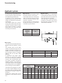
Flue Gas data
Boiler
type
Nominal
heat output
Nominal
heat input
Flue
gas
connecon
(DN)
CO
2
Level
Flue gas
temperature
Flue gas
quanty
Max
permissible
ue
resistance
THISION L
EVO
kW kW mm % °C g/s Pa
max min max min max min max min max min max min
60 56,5 15,5 57,9 16,0 100 8,5 9,0 59 57 25 7 167 15
70 65,5 15,6 66,8 16,0 100 8,4 9,0 60 57 29 7 200 15
80 75,3 19,4 76,8 19,8 100 8,4 9,0 61 58 33 8 200 15
100 92,9 18,7 95,2 19,0 100 8,4 8,5 60 56 41 8 173 15
120 111,9 22,5 114,3 22,9 100 8,4 8,5 63 56 49 10 134 15
140 130,4 26,2 133,3 26,7 130 8,2 8,5 66 57 58 11 200 15

Installaon
EN
19
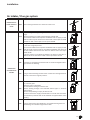
Air
intake / Flue gas system
Combuson air
drawn from the
room
B23 External ue gas exhaust. Air drawn from the room.
Combuson
air intake from
outside
C13
Air/exhaust gas roung through outside wall in the same pressure
range.
Exhaust gas/fresh air supply system through outside wall.
The Terminal outlets from separate combuson and air supply circuits
shall t inside a square of 50 cm for boilers with a heat input to 70 kW
and 100 cm with a heat input from 70 up to 100 kW.
C33
Flue gas exhaust and air sucon duct from outside with roof terminal
in the same range of pressure.
The Terminal outlets from separate combuson and air supply circuits
shall t inside a square of 50 cm and distance between the planes of
the two oreces shall be less than 50cm for boilers with a heat input
below 70 kW.
A square of 100 cm and distance between the planes of the two or-
eces shall be less than 100 cm with a heat input above 70 kW.
C43 Individual or shared ue gas exhaust and air sucon through ue duct-
ing built into the building.
C53 Flue gas exhaust leading outside and air sucon duct through external
wall not in the same range of pressure.
C63
Air and exhaust connecon to separate tested and supplied
air / exhaust pipes.
Basement / oor installaon.
Air and exhaust venng via exterior wall.
Exhaust venng through heat insulated exhaust pipe or moisture
resistant pipe.
Exhaust line (standing air layer) at exterior wall.
The terminals for the supply of combuson air and for the evacuaon
of combuson products shall not be installed on opposite walls of the
building.
C83 Flue gas exhaust through individual or shared ue ducng built into
the building. Air sucon through external wall.

Installaon
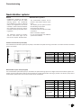
20
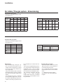
Air intake / Flue gas system - dimensioning
Twin Pipe ue gas system
Maximum permissible length of ue
gas system in m:
Twin Pipe flue
gas system
Equivalent length in m
Ø80 Ø100 Ø110 Ø125 Ø130
Straight
pipe
1 1 1 1 1
Bend R=D
90°/87°
1.5 1.8 2 2.2 2.2
Bend R=D
45°/43°
0.8 0.9 1 1 1
Concentric ue gas system
Maximum permissible length of ue
gas system in m:
Concentric
flue gas
system
Equivalent length in m
Bend R=D
90°/87°
Bend R=D
45°/43°
Ø100/150
1.5 1
Dimensioning
When dimensioning a ue gas sys-
tem, it’s necessary to perform a cal-
culaon check of the ue gas system
in order to verify if the choosen sys-
tem is applicable.
The previous tables show an example
of possible ue gas system, including
the maximum possible length of the
system.
This example only give an indicaon
of the possible length, but it can not
be used for ocial ue gas layout cal-
culaon. Each ue gas system has to
be calculated by an authorized com-
pany.
The maximum negave ue gas pres-
sure, which doesn’t aect the burner
modulaon rao, is 30 Pa. Higher
negave pressure will lead to limita-
on of the burner modulaon rao.
The maximum horizontal ue gas
length is 20 m. With horizontal
lengths longer than 20 m, a faultless
burner start in cold condion can not
be guaranteed.
Concentric ue gas system
The Boiler boiler models 60, 70, 80,
100 and 120 can be connected to a
concentric ue gas system.
Via a parallel-to-concentric adapter
(oponal) the boiler can be connect-
ed to:
• 100/150 concentric system.
See table for max. permissible ue
lengths.
TH-L Evo
Ø 80 / 125 Ø 100 / 150
60
14 38
70
12 33
80
7 23
100
- 11
120
- 7
Thision L
Evo
Ø80 Ø100 Ø110 Ø125 Ø130
Lmax
[m]
Lmax
[m]
Lmax
[m]
Lmax
[m]
Lmax
[m]
60
17 62 - - -
70
13 52 65 - -
80
7 36 47 - -
100
- 13 23 56 88
120
- 8 13 43 65
140
- - 5 14 23

23
Accessories
Single
Speed controlled pump
TH-L 50 - 85
Speed controlled pump
TH-L 100 - 145
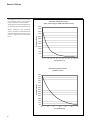
Residual head with standard pump
Flue adapter parallel
The boiler is equipped with a flue on-
ne tion of 100mm (TH-L 50-120) or
130mm (TH-L 145). In case of using
110mm or 125mm flue tem , the
original adapter can be repla ed a
follow :
•
PPUHSODFHGE\PP
•
130mm repla ed by 125mm.
Flue adapter concentric
Concentric flue tems an be used
on the THISION L 50-120, by using a
parallel to on entric adapter.
Air inlet cover
The inlet o er an be u ed to o er
the air inlet onne tion of the boiler in
non room sealed condition, available in
100mm and 130mm.
Accessori
Single
24
Scambiatore a piastre
Il set comprende uno scambiatore a
piastre, un profilo di montaggio, una
condotta di rac ordo per circuito
primario e il materiale di raccordo.
Lo s ambiatore di calore è di ponibile
per l'utilizzo con dT=20K, dT=15K o
dT=10K.
Per la scelta del sistema, vedi tabella
sottostante. L'i olamento dello
scambiatore è in dotazione.
Un disegno quotato è riportato a
pagina 26.
Adattatore parallelo gas combusti
La caldaia è dotata di fabbrica di un
raccordo gas combusti di 100 mm
(TH-L 65-120) o 130 mm (TH-L 145).
Per l'utilizzo di materiali con diametro
110 mm o 125 mm lato gas combusti,
l'adattatore originale può essere
sostituito con i seguenti adattatori
opzionali:
• 100 mm sostituito con 110 mm;
• 130 mm sostituito con 125 mm.
Adattatore concentrico gas
combusti
Le THISION L 65-120 possono essere
collegate a un sistema concentrico per
gas combusti utilizzando un adattatore
da parallelo a concentrico.
Griglia aspirazione aria
La griglia può essere utilizzata per
coprire l'apertura di aspirazione aria
della caldaia in regime di tiraggio
naturale; disponibile nelle dimensioni
100 mm e 130 mm.
TH-L 65 TH-L 85 TH-L 100 TH-L 120 TH-L 145
Circuito primario dT=20K m
3
/h 2.6 3.4 4.0 4.8 5.6
dT=20K Tipo PWT CB52-40L CB52-40L CB52-40L CB52-50L CB76-40H
m
3
/h 2.6 3.4 4.0 4.8 5.6
kPa 5.1 8.5 11.6 11.3 9.7
dT=15K Tipo PWT CB52-40L CB52-40L CB52-40L CB52-50L CB76-40H
m
3
/h 3.5 4.5 5.3 6.4 7.5
kPa 8.7 14.7 20.0 19.4 16.8
dT=10K Tipo PWT CB52-40L CB52-50L CB52-50L CB76-40H CB76-50H
m
3
/h 5.2 6.8 8.0 9.6 11.2
kPa 18.9 21.8 29.6 26.9 24.3
Circuito secondario
Vaso espansione L 2 2 2 2 2
100mm 60-120
130mm 140
Installaon
EN
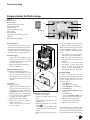
21
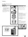
Air
intake / Flue gas system
Accessories
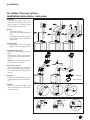
Types of boiler
Flue exhaust connecon
• coaxial connecon of the boiler to
the supply/exhaust ducng;
• split connecon of the boiler to
the exhaust ducng with air sup-
ply from outside.
The supply/exhaust ducng connec-
on kits are supplied separately from
the appliance, according to dierent
installaon soluons.
Air inlet cover
The inlet cover must be used to
cover the air inlet connecon of the
boiler in non room sealed condion,
available in 100mm and 130mm.
Flue adapter concentric
Concentric ue systems can be used
on the TH-L EVO 60-120, by using a
parallel to concentric adapter.
DN 100/150 = Ø
int
101
±0.3
/ 151
±0.3
DN 110/150 = Ø
int
111 /151
±0.5
- 0.6
±0.3
- 0.6
+0.3
- 0.6
+0.3
Flue adapter parallel
The boiler is equipped with a ue
connecon of 100mm (TH-L EVO 60-
120) or 130mm (TH-L EVO 140). In
case of using 110mm or 125mm ue
systems, the original adapter can be
replaced as follows:
• 100mm replaced by 110mm;
DN 110 = Ø
int
111
• 130mm replaced by 125mm.
DN 125 = Ø
int
126

> 500 mm
L > 250 mm
L >
250
L
>
250 mm
L > 250 mm
or
or
Max 1 meter
Max 2 meters
Max 1 meter
M&G • www.mg-flues.comM&G • www.mg-flues.com
max.
1000 mm
max.
1000 mm
max.
2000 mm
Clamp
3°
A
8-15 mm
!
B
Installaon
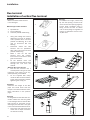
22
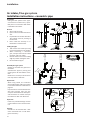
Air
intake /Flue gas system
Installaon instrucons - concentric pipe
Installaon
Fing the ue system to the appli-
ance must be carried out by a quali-
ed person in accordance with these
installaon instrucons.
General
• Store material inside.
• Pipes must be installed free of ten-
sion.
• Pay aenon to the ue direcon.
The sockets must be poinng to
the terminal.
• Don’t install the chimney on in-
ammable or wooden wall.
Cung the pipe
• Take out the inner tube by turning
it unl it releases from its posion.
• When shortening a concentric
pipe, cut equal amounts from both
the outer and inner tubes.
• Remove the burrs from the cung
edge to prevent cung the seals
• Re assemble the pipes.
Assembly ue gas system
Starng to assemble the pipes from
the boiler.
Assemble the pipes by turning and
pushing them ll the boom of the
seat.
NOTE: Don’t use soap or oil lubricant!
Use only water as lubricant.
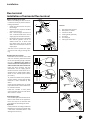
Pipes bends
When using bends, the maximum
permissible length of ue gas system
can be determined from the table on
page 19.
Pipe extensions must be xed to the
wall using support clips. Use one
clamp for each extension directly be-
side the sleeve. Fit another clamp to
the extension aer each 90° bend.
Important
Install only outside buildings on walls
constructed from re resistant mate-
rial.
Cleaning
Outside can be cleaned with a wet
cloth moistened with a mild deter-
gent if necessary.
Install tension free
La pagina si sta caricando...
La pagina si sta caricando...
La pagina si sta caricando...
La pagina si sta caricando...
La pagina si sta caricando...
La pagina si sta caricando...
La pagina si sta caricando...
La pagina si sta caricando...
La pagina si sta caricando...
La pagina si sta caricando...
La pagina si sta caricando...
La pagina si sta caricando...
La pagina si sta caricando...
La pagina si sta caricando...
La pagina si sta caricando...
La pagina si sta caricando...
La pagina si sta caricando...
La pagina si sta caricando...
La pagina si sta caricando...
La pagina si sta caricando...
La pagina si sta caricando...
La pagina si sta caricando...
La pagina si sta caricando...
La pagina si sta caricando...
La pagina si sta caricando...
La pagina si sta caricando...
La pagina si sta caricando...
-
 1
1
-
 2
2
-
 3
3
-
 4
4
-
 5
5
-
 6
6
-
 7
7
-
 8
8
-
 9
9
-
 10
10
-
 11
11
-
 12
12
-
 13
13
-
 14
14
-
 15
15
-
 16
16
-
 17
17
-
 18
18
-
 19
19
-
 20
20
-
 21
21
-
 22
22
-
 23
23
-
 24
24
-
 25
25
-
 26
26
-
 27
27
-
 28
28
-
 29
29
-
 30
30
-
 31
31
-
 32
32
-
 33
33
-
 34
34
-
 35
35
-
 36
36
-
 37
37
-
 38
38
-
 39
39
-
 40
40
-
 41
41
-
 42
42
-
 43
43
-
 44
44
-
 45
45
-
 46
46
-
 47
47


elco THISION L EVO Operation and Maintenance Manual
- Tipo
- Operation and Maintenance Manual
in altre lingue
- English: elco THISION L EVO
Documenti correlati
Altri documenti
-
Robur K18 Use Manual
-
Hamworthy Dorchester DR-TC Guida d'installazione
-
Sime Murelle Equipe 220 550 Box ErP Manuale del proprietario
-
-
Quantum GAS-FIRED BOILERS Manuale utente
-
Unical ALKON 140 EXT Guida d'installazione
-
 Unical !DEA B Guida d'installazione
-
Ariston Clas System 28 FF Scheda dati
-
Airwell CW-AR Installation and Maintenance Manual
-
Pitco 35C, 45C Manuale utente
