
de Betriebsanleitung Thermisches Überlastrelais
für explosionsgefährdete Bereiche .................................3
en
Operating instructions for thermal overload relay
for potentially explosive areas ........................................ 7
es
Manual de instrucciones relé térmico de sobrecarga
para áreas potencialmente explosivas .................................11
fr
Instructions de service relais thermique
pour zones explosibles................................................. 15
it
Istruzioni per l’uso relè termico
per zone a rischio d’esplosione .................................... 19
sv
Bruksanvisning för Termiskt överlastrelä för
explosionsfarliga omgivningar ......................................... 23
cn
用于有爆炸危险区域的热过载继电器使用说明书 ................. 27
ru
Руководствопоэксплуатациитепловогореле
перегрузкидлявзрывоопасныхзон ........................... 31
TF42
ATEX


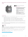
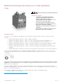
Thermisches Überlastrelais für explosionsgefährdete Bereiche
TF42
Sicherheitshinweise
• Montage und Installation dürfen nur von
ausgebildetem Fachpersonal, nach den
anerkannten technischen Regeln, Vorschriften
und relevanten Normen vorgenommen werden!
• Ungenügend angezogene Klemmschrauben
führen zu unzulässiger Erwärmung!
• Die zulässigen Umgebungsbedingungen sind zu
beachten (siehe technische Daten und Katalog).
• Geräte, die sichtbare Transportschäden
aufweisen, dürfen nicht eingesetzt werden
Allgemeine Beschreibung
Die erhöhte Gefahr bei Einsatz der Geräte in explosionsgefährdeten Bereichen verlangt die konsequente Beachtung folgender
Hinweise und Normen:
• EN 60079-0 Explosionsfähige Atmosphäre – Teil 0: Allgemeine Anforderungen
• EN 60079-1 Explosionsfähige Atmosphäre – Teil 1: Geräteschutz durch druckfeste Kapselung „d“
• EN 60079-7 Explosionsfähige Atmosphäre – Teil 7: Geräteschutz durch erhöhte Sicherheit „e“
• EN 60079-14 Explosionsfähige Atmosphäre - Teil 14: Projektierung, Auswahl und Errichtung elektrischer Anlagen
• EN 60079-17 Explosionsfähige Atmosphäre - Teil 17: Prüfung und Instandhaltung elektrischer Anlagen
• EN 60079-31 Explosionsfähige Atmosphäre – Teil 31: Geräte-Staubexplosionsschutz durch Gehäuse
• EN 50495 Sicherheitseinrichtungen für den sicheren Betrieb von Geräten im Hinblick auf Explosionsgefahren
Das thermische Überlastrelais TF42 ist zugelassen unter Gerätegruppe II, Kategorie (2) im Bereich „G“ (Bereiche, in denen
explosionsfähige Gas-, Dampf-, Nebel-, Luft-Gemische vorhanden sind) und zusätzlich für den Bereich „D“ (Bereiche mit
brennbarem Staub).
BVS 13 ATEX E 102
II (2) G
II (2) D
Das thermische Überlastrelais TF42 ist nicht für die Aufstellung bzw. den Betrieb im explosionsgefährdeten Bereich geeignet.
Bei Verwendung in explosionsgefährdeten Bereichen müssen die Geräte durch entsprechende Maßnahmen der erforderlichen
Zündschutzart entsprechen.
Für Starterkombinationen mit TF42 und Motorschhützen der AF-Reihe, sowie Einzelaufstellung DB42
ist ein geeigneter Kurzschlussschutz zur Erlangung einer Zuordnungsart „2“ nach EN 60947-4-1 zu wählen.
Entsprechende Informationen bezüglich geprüfter Starterkombinationen werden von ABB online bereitgestellt:
siehe „Coordination tables for motor protection“
http://applications.it.abb.com/SOC/Page/Selection.aspx
Warnung! Gefährliche Spannung!
2CDC106076M6801c / 04.2016 TF42 - 3

Hinweise
• Bei Ex-Anwendungen ist ein Nachweis der Wirksamkeit der installierten Schutzeinrichtungen vor der Inbetriebnahme
erforderlich!
• Die Schutzfunktion des Gerätes ist der thermische Überlastschutz von Motoren. Im Überlastfall wird der Motor, durch
Öffnen des NC-Kontaktes des elektromechanischen Überlastrelais abgeschaltet.
• Der sichere Zustand ist ein geöffneter NC-Kontakt des Gerätes, über den das Lastschütz gesteuert wird.
Montage und Inbetriebnahme
Der Austausch des TF42 darf nur durch ein gleichwertiges, den Vorschriften entsprechend gekennzeichnetes Gerät erfolgen.
In Anwendungen zum Schutz von Motoren in explosionsgefährdeten Bereichen, darf das Gerät nur mit Einstellung
„manuelles Rücksetzen“ betrieben werden.
• Einstellung des Motornennstroms am frontseitigen Einstellknopf.
Hierzu am TF42 die Einstellung auf den Nennstromwert des Motors, gemäß Vorgabe EG-Baumusterprüfbescheinigung
bzw. Typenschild vornehmen.
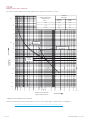
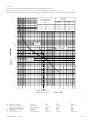
Bei der Auswahl des Überlastrelais ist die Eignung anhand der Auslösekennlinien bzw. Auslöseklasse zu überprüfen.
Maßgebend sind die Werte für das Verhältnis Motoranlauf I
A
zu Motornennstrom I
N
und die kürzeste t
E
-Zeit, die in der
ATEX-Konformitätsbescheinigung oder in der EG-Baumusterprüfbescheinigung und auf dem Typenschild des Motors vermerkt
sein müssen. Das Thermische Überlastrelais muss innerhalb der t
E
-Zeit auslösen, d. h., die Auslösekennlinie aus kaltem Zustand
muss unterhalb des Koordinatenpunktes I
A
/I
N
und der t
E
-Zeit verlaufen.
Dieses Gerät ist gegen unberechtigte Modifikation (Einstellung I
e
, Man/Auto Reset) durch Plombieren der Abdeckung zu sichern.
Die Anschlussleitungen sind entsprechend den Vorgaben, bzw. den anzuwendenden Normen zu dimensionieren.
Sicherheitsdaten TF42
Gemäß DIN EN 50495 können an eine Sicherheitseinrichtung für die Kategorie 2G und 2D die Anforderungen
an ein SIL1 und eine HFT = 0 gestellt werden.
Das thermische Überlastrelais der Baureihe TF42 kann als Komponente einer Sicherheitseinrichtung,
z. B. zusammen mit einem geeigneten Lastsschütz, diese Anforderungen erfüllen.
2CDC106076M6801c / 04.20164 - TF42 |

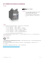
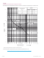
Beispiel:
Der Motor mit erhöhter Sicherheit hat folgende Daten:
400 V, 50 Hz/60Hz, 7,5 kW, I
e
= 15 A, I
A
/I
N
= 7,4, Temperaturklasse T3, t
E
-Zeit = 11s
Nach unten stehender Auslösekurve liegt die Auslösezeit unterhalb der t
E
-Zeit des Motors.
4)
3)
5)
1)
2)
2)
1)
3)4)
Auslösezeit t
tripping time
2
1
20
10
1
2
3
4
5
50
40
30
20
10
7
5
4
3
2
1
0.1
0.05
0.005
0.01
Std
s
min
x
multiples of rated current I
e
Vielfaches vom Nennstrom I
e
1
1.2
1.5
2
4
6
8
10
15
20
30
40
60
80
7.2
I
e
3 100
7.7 s 8.7 s
5.1 s 4.7 s
Vielfaches vom Nennstrom
tripping time
Auslösezeit
3 polig
three pole
two pole
2 polig
multiples of rated
current
21.2 s
3 x Ie
5 x Ie
7.2 x Ie
17.7 s
2 polig
two pole
3 polig
three pole
fuse 80 A gG
Sicherung 80 A gG
Beispiel
1) 2) 3) 4) 5)
de Vielfaches vom Nennstrom Auslösezeit 2-polig 3-polig Sicherung
es Múltiplos de la intensidad aplicada tiempo de disparo de 2 polos de 3 polos Fusible
fr Multiple du courant de reglage Temps de déclenchement 2 broches 3 broches Fusible
it Multiplo della corrente di regolazione Tempo di apertura Bipolare Tripolare Fusibile
sv Multipelfaktor för utlösningsström Utlösningstid 2-polig 3-polig Säkring
cn 标称电流的多倍 触发时间 双极 三极 保险丝
ru кратностьноминальноготока Времясрабатывания 2-полюсное 3-полюсное Предохранитель
2CDC106076M6801c / 04.2016 TF42 - 5

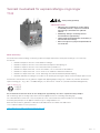
Auslösekennlinien aus kaltem Zustand
Für Nennströme zwischen dem 3- und 8-fachen des Einstellwertes beträgt die Toleranz ±20%
Auslösezeit t
tripping time
2
1
20
10
1
2
3
4
5
50
40
30
20
10
7
5
4
3
2
1
0.1
0.05
0.005
0.01
Std
s
min
x
multiples of rated current I
e
Vielfaches vom Nennstrom I
e
1
1.2
1.5
2
4
6
8
10
15
20
30
40
60
80
7.2
I
e
3 100
7.7 s 8.7 s
5.1 s 4.7 s
Vielfaches vom Nennstrom
tripping time
Auslösezeit
3 polig
three pole
two pole
2 polig
multiples of rated
current
21.2 s
3 x Ie
5 x Ie
7.2 x Ie
17.7 s
2 polig
two pole
3 polig
three pole
fuse 80 A gG
Sicherung 80 A gG
Auslösekennlinien aus kaltem Zustand für TF42-35
Die technischen Daten und Kennlinien für weitere Strombereiche finden Sie auf unserer Internetseite
http://www.abb.com/abblibrary/downloadcenter/?CategoryID=9AAC157706&View=Result&QueryText=tf42&SortBy=Score
TF42
2CDC106076M6801c / 04.20166 - TF42 |

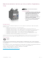
Thermal overload relay for potentially explosive areas
TF42
Safety instructions
• Mounting and installation may only be done by
trained technical personnel, according to the
recognized technical rules, regulations, and
relevant standards!
• Insufficiently tightened locking screws lead to
an inadmissible rise in temperature!
• Always observe the permitted ambient
conditions (see technical data and catalog).
• Devices with visible transport damage must not
be used.
General description
The extended risks when using these devices in potentially explosive areas requires consistent adherence to the following notes
and standards:
• EN 60079-0 Explosive atmospheres – Part 0: General requirements
• EN 60079-1 Explosive atmospheres – Part 1: Equipment protection by flameproof enclosure "d"
• EN 60079-7 Explosive atmospheres – Part 7: Equipment protection by increased safety "e"
• EN 60079-14 Explosive atmospheres - Part 14: Electrical installations design, selection and erection
• EN 60079-17 Explosive atmospheres - Part 17: Electrical installations inspection and maintenance
• EN 60079-31 Explosive atmospheres – Part 31: Equipment dust ignition protection by enclosure
• EN 50495 Safety devices required for the safe functioning of equipment with respect to explosion risks
The TF42 thermal overload relay is authorized under device group II, category (2) in the "G" area (areas with potentially explosive
gas, steam, smoke or air mixtures) and additionally for the "D" area (areas with combustible dust).
BVS 13 ATEX E 102
II (2) G
II (2) D
The TF42 thermal overload relay is not suitable for installation and/or operation in potentially explosive areas.
When using the devices in potentially explosive areas, preventive measures must be taken, e. g. within suitable enclosure.
For starter combinations with TF42 devices and AF motor contactors, as well as with DB42 single mounting kit, appropriate
protection against short-circuit is to be selected for reaching coordination type "2" according to EN 60947-4-1.
Information regarding verified starter combinations is provided online by ABB.
see "Coordination tables for motor protection"
http://applications.it.abb.com/SOC/Page/Selection.aspx
Warning! Hazardous voltage!
2CDC106076M6801c / 04.2016 TF42 - 7

Notes
• For explosion-proof applications, the efficiency of the installed protection devices has to be verified prior to
commissioning!
• The protection function of the device is the thermal overload protection of motors. In case of an overload trip, the motor
is switched off by opening the NC contact of the electromechanical overload relay.
• The safe state is an open NC contact of the device used to control the load contactor.
Mounting and commissioning
The TF42 may only be replaced by an equivalent device, marked in accordance with the regulations.
For applications protecting motors in potentially explosive areas, the device may only be used if it is configured for
"manual reset".
• Setting the rated motor current is done using the adjusting knob on the front side.
For this purpose, the rated motor current has to be adjusted on the TF42 according to the EC type examination
certificate specification and/or the type plate.
When selecting the overload relay, check its suitability by means of the trip curves and/or the trip class. Decisive values are the
ratio between the motor startup current I
A
and the rated motor current I
N
, as well as the shortest time t
E
. These values have
to be marked in the ATEX certificate of conformity or in the EC type examination certicate and on the type plate of the motor.
The thermal overload relay must trip within the time t
E
. This means that the trip curve from the cold state has to be below the
coordination point I
A
/I
N
and the time t
E
.
It is necessary to ensure protection against unauthorized adjustment (I
e
setting, Man/Auto reset) by sealing the cover.
The connecting cables have to be dimensioned according to the specifications and/or the applicable standards.
Safety specifications TF42
According to DIN EN 50495, the requirements for a SIL 1 and a HFT = 0 can be placed on safety equipment for categories 2G
and 2D.
The TF42 thermal overload relay can meet these requirements if used as a component of the safety equipment, e.g. in
cooperation with a suitable load contactor.
2CDC106076M6801c / 04.20168 - TF42 |

Example:
The motor with enhanced safety has the following data:
400 V, 50 Hz/60Hz, 7.5 kW, I
e
= 15 A, I
A
/I
N
= 7.4, temperature class T3, time t
E
= 11s
According to the tripping curve below , the trip time is smaller than the time t
E
of the motor.
4)
3)
5)
1)
2)
2)
1)
3)4)
Auslösezeit t
tripping time
2
1
20
10
1
2
3
4
5
50
40
30
20
10
7
5
4
3
2
1
0.1
0.05
0.005
0.01
Std
s
min
x
multiples of rated current I
e
Vielfaches vom Nennstrom I
e
1
1.2
1.5
2
4
6
8
10
15
20
30
40
60
80
7.2
I
e
3 100
7.7 s 8.7 s
5.1 s 4.7 s
Vielfaches vom Nennstrom
tripping time
Auslösezeit
3 polig
three pole
two pole
2 polig
multiples of rated
current
21.2 s
3 x Ie
5 x Ie
7.2 x Ie
17.7 s
2 polig
two pole
3 polig
three pole
fuse 80 A gG
Sicherung 80 A gG
Example
1) 2) 3) 4) 5)
de Vielfaches vom Nennstrom Auslösezeit 2-polig 3-polig Sicherung
es Múltiplos de la intensidad aplicada tiempo de disparo de 2 polos de 3 polos Fusible
fr Multiple du courant de reglage Temps de déclenchement 2 broches 3 broches Fusible
it Multiplo della corrente di regolazione Tempo di apertura Bipolare Tripolare Fusibile
sv Multipelfaktor för utlösningsström Utlösningstid 2-polig 3-polig Säkring
cn 标称电流的多倍 触发时间 双极 三极 保险丝
ru кратностьноминальноготока Времясрабатывания 2-полюсное 3-полюсное Предохранитель
2CDC106076M6801c / 04.2016 TF42 - 9

Tripping curves from a cold state
For nominal currents between three and eight times the setpoint, the tolerance is ±20%
Auslösezeit t
tripping time
2
1
20
10
1
2
3
4
5
50
40
30
20
10
7
5
4
3
2
1
0.1
0.05
0.005
0.01
Std
s
min
x
multiples of rated current I
e
Vielfaches vom Nennstrom I
e
1
1.2
1.5
2
4
6
8
10
15
20
30
40
60
80
7.2
I
e
3 100
7.7 s 8.7 s
5.1 s 4.7 s
Vielfaches vom Nennstrom
tripping time
Auslösezeit
3 polig
three pole
two pole
2 polig
multiples of rated
current
21.2 s
3 x Ie
5 x Ie
7.2 x Ie
17.7 s
2 polig
two pole
3 polig
three pole
fuse 80 A gG
Sicherung 80 A gG
Tripping curves for TF42-35 from a cold state
The technical specifications and characteristic curves for other current ranges can be found on our Web site
http://www.abb.com/abblibrary/downloadcenter/?CategoryID=9AAC157706&View=Result&QueryText=tf42&SortBy=Score
TF42
2CDC106076M6801c / 04.201610 - TF42 |

Relé térmico de sobrecarga para áreas potencialmente explosivas
TF42
Instrucciones de seguridad
• ¡El montaje y la instalación únicamente deberán
ser efectuados por personal especializado
con la respectiva formación profesional,
en conformidad con las reglas técnicas
reconocidas, las especificaciones y normas
relevantes!
• ¡Tornillos de conexión no apretados
suficientemente causarán un calentamiento
inadmisible!
• Se deberán observar las condiciones
ambientales admisibles (véanse los datos
técnicos y el catálogo).
• No se deberán emplear aquellos dispositivos
que muestren daños de transporte visibles
Descripción general
Los riesgos al emplear los dispositivos en áreas potencialmente explosivas exigen la observación consecuente de las siguientes
instrucciones y normas:
• EN 60079-0 Atmósferas explosivas – Parte 0: Requerimientos generales
• EN 60079-1 Atmósferas explosivas – Parte 1: Protección de equipos mediante envolvente antideflagrante "d"
• EN 60079-7 Atmósferas explosivas – Parte 7: Protección de equipos mediante mayor seguridad "e"
• EN 60079-14 Atmósferas explosivas – Parte 14: Diseño, elección y realización de instalaciones eléctricas
• EN 60079-17 Atmósferas explosivas – Parte 17: Inspección y mantenimiento de instalaciones eléctricas
• EN 60079-31 Atmósferas explosivas – Parte 31: Protección contra explosión de polvo de equipos mediante carcasa
• EN 50495 Dispositivos de seguridad requeridos para el funcionamiento seguro de un equipo respecto a los riesgos de
explosión
El relé térmico de sobrecarga TF42 forma parte del grupo de dispositivos II, categoría (2) y está homologado para el uso en
entornos de la categoría "G" (existencia de mezclas explosivas de gas, vapor, humo o mezclas de aire) y adicionalmente para el
entorno "D" (existencia de polvo inflamable).
BVS 13 ATEX E 102
II (2) G
II (2) D
El relé térmico de sobrecarga TF42 no es apropiado para la instalación o bien el funcionamiento en áreas potencialmente
explosivas. En caso de su utilización en áreas potencialmente explosivas, los dispositivos deberán corresponder al tipo de
protección requerido adoptando las medidas correspondientes.
Para las combinaciones de arranque de motor con TF42 y contactores de la serie AF, así como instalación individual mediante
DB42 se deberá seleccionar una protección contra cortocircuitos apropiada para obtener coordinación Tipo "2" según
EN 60947-4-1.
ABB pone a disposición los datos referentes a combinaciones comprobadas de motores de arranque en Internet:
véase "Coordination tables for motor protection"
http://applications.it.abb.com/SOC/Page/Selection.aspx
¡Advertencia! ¡Tensión peligrosa!
2CDC106076M6801c / 04.2016 TF42 - 11

Notas
• ¡En el caso de aplicaciones Ex, se requerirá la demostración de la eficacia de los dispositivos de protección instalados
antes de la puesta en funcionamiento!
• La función de protección del dispositivo es la protección de sobrecarga térmica de motores. En caso de sobrecarga, el
motor será apagado mediante la apertura del contacto NC del relé de sobrecarga electromecánico.
• El estado seguro es el contacto NC abierto del dispositivo, a través del cual se controla el contactor de carga.
Montaje y puesta en funcionamiento
La sustitución del TF42 únicamente deberá ser realizada con algún dispositivo equivalente, marcado en concrdancia con las
normativas vigentes.
En aplicaciones para la protección de motores en áreas potencialmente explosivas, el dispositivo únicamente deberá ser
operado con el ajuste "reset manual".
• Ajuste de la corriente nominal del motor a través del botón de ajuste en el lado frontal.
Para esto, efectuar el ajuste del valor de corriente nominal del motor en el TF42 según la especificación del certificado de
examen CE de tipo o bien de la placa de características.
Al seleccionar el relé de sobrecarga, se deberá comprobar su idoneidad a base de las curvas características de disparo o bien la
clase de disparo. Prevalecerán los valores para la relación de corriente de arranque del motor I
A
y corriente nominal del motor I
N
y el tiempo t
E
más corto, los cuales deberán estar anotados en el certificado de conformidad ATEX o en el certicado de examen
CE de tipo y en la placa de características del motor. El relé térmico de sobrecarga deberá disparar dentro del tiempo t
E
, es decir
que la curva característica de disparo desde el estado frío deberá desarrollarse por debajo del punto de coordenadas I
A
/I
N
y el
tiempo t
E
.
Este dispositivo deberá ser protegido de cualquier modificación no autorizada (ajuste de I
e
, reset man/auto) instalando un
precinto en la cubierta.
Los cables de conexión deberán ser dimensionados en conformidad con las especificaciones o bien las normas aplicables.
Datos de seguridad TF42
Según DIN EN 50495, los requerimientos para un SIL1 y HFT=0 deben ser satisfechos en dispositivos de seguridad categoría
2G y 2D.
El relé térmico de sobrecarga de la serie TF42, como componente de un dispositivo de seguridad,
puede satisfacer estas exigencias, p. ej. con un contactor de carga apropiado.
2CDC106076M6801c / 04.201612 - TF42 |

Ejemplo:
El motor con seguridad aumentada presenta los siguientes datos:
400 V, 50 Hz/60Hz, 7,5 kW, I
e
= 15 A, I
A
/I
N
= 7,4, clase de temperatura T3, tiempo t
E
= 11s
Según la curva de disparo indicada más abajo, el tiempo de disparo se encuentra por debajo del tiempo t
E
del motor.
4)
3)
5)
1)
2)
2)
1)
3)4)
Auslösezeit t
tripping time
2
1
20
10
1
2
3
4
5
50
40
30
20
10
7
5
4
3
2
1
0.1
0.05
0.005
0.01
Std
s
min
x
multiples of rated current I
e
Vielfaches vom Nennstrom I
e
1
1.2
1.5
2
4
6
8
10
15
20
30
40
60
80
7.2
I
e
3 100
7.7 s 8.7 s
5.1 s 4.7 s
Vielfaches vom Nennstrom
tripping time
Auslösezeit
3 polig
three pole
two pole
2 polig
multiples of rated
current
21.2 s
3 x Ie
5 x Ie
7.2 x Ie
17.7 s
2 polig
two pole
3 polig
three pole
fuse 80 A gG
Sicherung 80 A gG
Ejemplo
1) 2) 3) 4) 5)
de Vielfaches vom Nennstrom Auslösezeit 2-polig 3-polig Sicherung
es Múltiplos de la intensidad aplicada tiempo de disparo de 2 polos de 3 polos Fusible
fr Multiple du courant de reglage Temps de déclenchement 2 broches 3 broches Fusible
it Multiplo della corrente di regolazione Tempo di apertura Bipolare Tripolare Fusibile
sv Multipelfaktor för utlösningsström Utlösningstid 2-polig 3-polig Säkring
cn 标称电流的多倍 触发时间 双极 三极 保险丝
ru кратностьноминальноготока Времясрабатывания 2-полюсное 3-полюсное Предохранитель
2CDC106076M6801c / 04.2016 TF42 - 13

Curvas características de disparo desde el estado frío
Para corrientes nominales entre 3 y 8 veces el valor de ajuste, la tolerancia será de ±20%
Auslösezeit t
tripping time
2
1
20
10
1
2
3
4
5
50
40
30
20
10
7
5
4
3
2
1
0.1
0.05
0.005
0.01
Std
s
min
x
multiples of rated current I
e
Vielfaches vom Nennstrom I
e
1
1.2
1.5
2
4
6
8
10
15
20
30
40
60
80
7.2
I
e
3 100
7.7 s 8.7 s
5.1 s 4.7 s
Vielfaches vom Nennstrom
tripping time
Auslösezeit
3 polig
three pole
two pole
2 polig
multiples of rated
current
21.2 s
3 x Ie
5 x Ie
7.2 x Ie
17.7 s
2 polig
two pole
3 polig
three pole
fuse 80 A gG
Sicherung 80 A gG
Curvas características de disparo desde el estado frío para TF42-35
Los datos técnicos y las curvas características para otros rangos de corriente se encuentran en nuestra página web
http://www.abb.com/abblibrary/downloadcenter/?CategoryID=9AAC157706&View=Result&QueryText=tf42&SortBy=Score
TF42
2CDC106076M6801c / 04.201614 - TF42 |

Relais de surcharge thermique pour zones explosives
TF42
Consignes de sécurité
• Le montage et l’installation doivent être
exécutés exclusivement par du personnel
qualifié et dûment formé, selon les
réglementations techniques applicables et en
respectant les normes en vigueur !
• Des vis de serrage insuffisamment serrées
peuvent provoquer un échauffement excessif !
• Respecter les conditions ambiantes
admissibles (cf. Caractéristiques techniques et
catalogue).
• Ne pas utiliser les appareils qui présentent des
dommages visibles dus au transport.
Description générale
Le risque accru lors de l‘utilisation des appareils en zones explosives demande le respect strict des consignes et normes
suivantes :
• EN 60079-0 Atmosphères explosives – Partie 0 : Exigences générales
• EN 60079-1 Atmosphères explosives – Partie 1 : Protection du matériel par enveloppes antidéflagrantes « d »
• EN 60079-7 Atmosphères explosives – Partie 7 : Protection de l’équipement par sécurité augmentée « e »
• EN 60079-14 Atmosphères explosives – Partie 14 : Conception, sélection et construction des installations électriques
• EN 60079-17 Atmosphères explosives – Partie 17 : Inspection et maintenance des installations électriques
• EN 60079-31 Atmosphères explosives – Partie 31 : Protection du matériel contre l’inflammation des poussières par
enveloppe
• EN 50495 Dispositifs de sécurité nécessaires pour le fonctionnement sûr d’un matériel vis-à-vis des risques d’explosion
Le relais de surcharge thermique TF42 est certifié pour le groupe d‘appareils II, catégorie (2) dans la zone « G » (zones où se
trouvent des mélanges explosifs de gaz, de vapeur, de brouillard et d‘air) ainsi que pour la zone « D » (zones avec poussières
combustibles).
BVS 13 ATEX E 102
II (2) G
II (2) D
Le relais de surcharge thermique TF42 n‘est pas approprié pour une implantation ou bien un fonctionnement dans des zones
explosives. En cas d‘utilisation dans des zones explosives, les appareils doivent être conformes au mode de protection requis en
prenant les mesures appropriées.
Pour des ensembles démarreurs avec relais de surcharge thermique TF42 et contacteurs de la série AF ainsi que pour une
implantation individuelle DB42, sélectionner une protection contre les courts-circuits approprié pour assurer une coordination de
type « 2 » selon la norme EN 60947-4-1.
Des informations supplémentaires relatives aux ensembles démarreurs certifiés sont disponibles en ligne :
cf. « Coordination tables for motor protection »
http://applications.it.abb.com/SOC/Page/Selection.aspx
Avertissement! Tension électrique dangereuse!
2CDC106076M6801c / 04.2016 TF42 - 15

Notes
• Pour des applications Ex, il est indispensable de certifier l’efficacité des dispositifs de protection installés avant la mise en
service !
• La fonction de l’appareil est de protéger des moteurs d’une surcharge thermique. En cas de surcharge, l’alimentation du
moteur sera coupée en ouvrant le contact NF du relais de surcharge électromécanique.
• La sécurité est assurée par un contact NF permettant de commander le contacteur de charge.
Montage et mise en service
Le remplacement du relais TF 42 s‘effectue toujours par un appareil de même type marqué conformément aux prescriptions en
vigueur.
Dans des applications conçues pour la protection de moteurs en zones explosives, ne faire fonctionner l‘appareil qu‘avec le
réglage « Réinitialisation manuelle ».
• Le réglage du courant nominal moteur s’effectue par rotation du potentiomètre sur la face avant. Le courant nominal du
moteur doit être réglé conformément aux spécifications CE et/ou aux données de la plaque signalétique du moteur.
Lors de la sélection du relais de surcharge thermique, s‘assurer de son adéquation au besoin à l‘aide des caractéristiques
techniques et de la classe de déclenchement. Les valeurs à prendre en compte sont le rapport entre le courant de démarrage
moteur I
A
et le courant nominal I
N
, et le temps de déclenchement t
E
. Ces valeurs doivent figurer dans le certificat ATEX, ou
dans l‘attestation d‘examen CE ou sur la plaque signalétique du moteur. Le relais de surcharge thermique doit déclencher
dans un temps inférieur au temps t
E
, en d‘autre termes, la courbe de déclenchement à l‘état froid doit passer en dessous des
coordonnées du point I
A
/I
N
; t
E
(voir exemple).
Protéger cet appareil contre toute modification non autorisée (réglage I
e
, Réinitialisation Man/Auto) en apposant des plombs sur
le couvercle.
Le dimensionnement des câbles de raccordement doit s‘effectuer conformément aux spécifications ou bien aux normes en
vigueur.
Données de sécurité relais TF42
Selon la norme DIN EN 50495, un dispositif de sécurité prévu pour la catégorie 2G et 2D doit remplir les exigences suivantes :
SIL1 et HFT = 0.
Le relais de surcharge thermique de la série TF42 peut satisfaire à ces exigences comme composant d‘un dispositif de sécurité,
par ex. conjointement avec un contacteur de charge.
2CDC106076M6801c / 04.201616 - TF42 |

Exemple :
Pour un moteur à sécurité renforcée présentant les caractéristiques suivantes :
400 V, 50 Hz/60 Hz, 7,5 kW, I
e
= 15 A, I
A
/I
N
= 7,4, classe de température T3, temps t
E
= 11 s
Selon la courbe de déclenchement ci-dessous, le temps de déclenchement est au-dessous du temps t
E
du moteur.
4)
3)
5)
1)
2)
2)
1)
3)4)
Auslösezeit t
tripping time
2
1
20
10
1
2
3
4
5
50
40
30
20
10
7
5
4
3
2
1
0.1
0.05
0.005
0.01
Std
s
min
x
multiples of rated current I
e
Vielfaches vom Nennstrom I
e
1
1.2
1.5
2
4
6
8
10
15
20
30
40
60
80
7.2
I
e
3 100
7.7 s 8.7 s
5.1 s 4.7 s
Vielfaches vom Nennstrom
tripping time
Auslösezeit
3 polig
three pole
two pole
2 polig
multiples of rated
current
21.2 s
3 x Ie
5 x Ie
7.2 x Ie
17.7 s
2 polig
two pole
3 polig
three pole
fuse 80 A gG
Sicherung 80 A gG
Exemple
1) 2) 3) 4) 5)
de Vielfaches vom Nennstrom Auslösezeit 2-polig 3-polig Sicherung
es Múltiplos de la intensidad aplicada tiempo de disparo de 2 polos de 3 polos Fusible
fr Multiple du courant de reglage Temps de déclenchement 2 broches 3 broches Fusible
it Multiplo della corrente di regolazione Tempo di apertura Bipolare Tripolare Fusibile
sv Multipelfaktor för utlösningsström Utlösningstid 2-polig 3-polig Säkring
cn 标称电流的多倍 触发时间 双极 三极 保险丝
ru кратностьноминальноготока Времясрабатывания 2-полюсное 3-полюсное Предохранитель
2CDC106076M6801c / 04.2016 TF42 - 17

Courbes de déclenchement à l‘état froid
La tolérance est de ±20 % pour des courants nominaux entre 3 et 8 fois la valeur de consigne la valeur de consigne
Auslösezeit t
tripping time
2
1
20
10
1
2
3
4
5
50
40
30
20
10
7
5
4
3
2
1
0.1
0.05
0.005
0.01
Std
s
min
x
multiples of rated current I
e
Vielfaches vom Nennstrom I
e
1
1.2
1.5
2
4
6
8
10
15
20
30
40
60
80
7.2
I
e
3 100
7.7 s 8.7 s
5.1 s 4.7 s
Vielfaches vom Nennstrom
tripping time
Auslösezeit
3 polig
three pole
two pole
2 polig
multiples of rated
current
21.2 s
3 x Ie
5 x Ie
7.2 x Ie
17.7 s
2 polig
two pole
3 polig
three pole
fuse 80 A gG
Sicherung 80 A gG
Courbes de déclenchement à l‘état froid pour TF42-35
Vous trouverez les caractéristiques techniques et courbes pour d’autres plages d’intensité sur notre site Internet
http://www.abb.com/abblibrary/downloadcenter/?CategoryID=9AAC157706&View=Result&QueryText=tf42&SortBy=Score
TF42
2CDC106076M6801c / 04.201618 - TF42 |

Relè di sovraccarico termico per zone a rischio d’esplosione
TF42
Istruzioni di sicurezza
• Le operazioni di montaggio e installazione sono
riservate a personale specializzato esperto delle
regole della tecnica comunemente accettate,
disposizioni e della relativa normativa!
• Il serraggio non corretto dei morsetti può
provocare un surriscaldamento eccessivo!
• Rispettare le condizioni ambientali ammesse (si
vedano i dati tecnici e il catalogo).
• Non è ammessa l'installazione del dispositivo
nel caso siano presenti evidenti danni da
trasporto.
Descrizione generale
Il maggior rischio dovuto all’utilizzo dei dispositivi in zone a rischio d’esplosione richiede il rigoroso rispetto delle seguenti
indicazioni e norme:
• EN 60079-0 Atmosfere esplosive – Parte 0: Requisiti generali
• CEI EN 60079-1 Atmosfere esplosive – Parte 1: Protezione mediante custodia a prova d’esplosione "d"
• CEI EN 60079-7 Atmosfere esplosive – Parte 7: Apparecchiature con modo di protezione a sicurezza aumentata "e"
• CEI EN 60079-14 Atmosfere esplosive – Parte 14: Progettazione, scelta e installazione degli impianti elettrici
• CEI EN 60079-17 Atmosfere esplosive – Parte 17: Verifica e manutenzione degli impianti elettrici
• CEI EN 60079-31 Atmosfere esplosive – Parte 31: Protezione contro polveri combustibili mediante custodia
• CEI EN 50495 sistemi di sicurezza negli impianti con rischio di esplosione
Il relè di sovraccarico termico TF42 è omologato per il gruppo dispositivi II, categoria (2) nell’area "G" (area nella quale sono
presenti miscele di gas, vapore, nebbia e aria deflagranti) e inoltre per l’area zona "D" (area con polveri esplosive).
BVS 13 ATEX E 102
II (2) G
II (2) D
Il relè di sovraccarico termico TF42 non è idoneo all’utilizzo e al funzionamento in zone a rischio d’esplosione.
In caso di installazione in zone a rischio d’esplosione, i dispositivi devono essere dotati del tipo di protezione antideflagrante con
misure addizionali.
Per le combinazioni con TF42 e contattori della Serie AF, nonché per l’utilizzo isolato di DB42 si dovrà prevedere una protezione
contro corto circuito atta ad ottenere un coordinamento "tipo 2" secondo la norma CEI EN 60947-4-1.
Il database completo delle tabelle di coordinamento è disponibile sul sito Web ABB:
si vedano le "Coordination tables for motor protection"
http://applications.it.abb.com/SOC/Page/Selection.aspx
Avvertenza! Tensione pericolosa!
2CDC106076M6801c / 04.2016 TF42 - 19

Indicazioni
• Per applicazioni Ex, prima della messa in funzione è necessaria la dimostrazione dell’efficacia delle protezioni installate!
• Il relè svolge la funzione di protezione contro il sovraccarico termico di motori. In caso di sovraccarico il motore sarà
arrestato dall’apertura del contattore di potenza azionato mediante l’apertura del contatto NC del relè elettromeccanico
di protezione.
• La sicurezza sulla disattivazione del contattore è garantita dall’apertura del contatto NC del relè termico.
Installazione e messa in servizio
La sostituzione del relè TF42 è permessa solo con un dispositivo equivalente, contrassegnato come richiesto dalla normativa.
In applicazioni per la protezione di motori in zone a rischio d’esplosione, l’utilizzo del dispositivo è permesso solo con
l’impostazione "Reset manuale".
• Impostazione della corrente motore nominale con il trimmer frontale.
Sul TF42 impostare il valore della corrente nominale del motore in base all’omologazione di tipo CE risp. alla targhetta
conoscitiva.
Per selezionare un relè di sovraccarico adatto, verificarne l’idoneità in base alle caratteristiche d’intervento rispondenti alla
classe d’intervento. Sono fondamentali i valori per il rapporto tra la corrente di avviamento I
A
e la corrente motore nominale
I
N
e il l’intervallo minimo t
E
che devono essere riportati nella dichiarazione di conformità ATEX o nell’omologazione di tipo CE
nonché sulla targhetta conoscitiva del motore. Il relè di sovraccarico termico deve intervenire entro il tempo t
E
, la caratteristica
d’intervento allo stato a freddo cioè deve essere inferiore alla coordinata I
A
/I
N
e al tempo t
E
.
Proteggere questo dispositivo contro interventi di modifica non autorizzati (impostazione I
e
, riarmo Man/Auto) piombando la
copertura.
Dimensionare i cavi di connessione in base alle indicazione risp. alla normativa applicabile.
Dati di sicurezza TF42
In base alla DIN EN 50495, a un dispositivo di sicurezza per la categoria 2G e 2D si possono richiedere i requisiti
richiesti a un SIL1 e a una HFT = 0.
Il relè di sovraccarico termico della Serie TF42 utilizzato in combinazione con un contattore adeguatamente dimensionato è in
grado di soddisfare questi requisiti.
2CDC106076M6801c / 04.201620 - TF42 |
La pagina si sta caricando...
La pagina si sta caricando...
La pagina si sta caricando...
La pagina si sta caricando...
La pagina si sta caricando...
La pagina si sta caricando...
La pagina si sta caricando...
La pagina si sta caricando...
La pagina si sta caricando...
La pagina si sta caricando...
La pagina si sta caricando...
La pagina si sta caricando...
La pagina si sta caricando...
La pagina si sta caricando...
La pagina si sta caricando...
La pagina si sta caricando...
La pagina si sta caricando...
La pagina si sta caricando...
-
 1
1
-
 2
2
-
 3
3
-
 4
4
-
 5
5
-
 6
6
-
 7
7
-
 8
8
-
 9
9
-
 10
10
-
 11
11
-
 12
12
-
 13
13
-
 14
14
-
 15
15
-
 16
16
-
 17
17
-
 18
18
-
 19
19
-
 20
20
-
 21
21
-
 22
22
-
 23
23
-
 24
24
-
 25
25
-
 26
26
-
 27
27
-
 28
28
-
 29
29
-
 30
30
-
 31
31
-
 32
32
-
 33
33
-
 34
34
-
 35
35
-
 36
36
-
 37
37
-
 38
38


in altre lingue
Documenti correlati
Altri documenti
-
Shimano CS-9000 Dealer's Manual
-
Shimano CS-R7000 Dealer's Manual
-
SICK RS25-WL334000 Istruzioni per l'uso
-
 Rockwell Automation E1 PLUS Application And Installation Bulletin
-
WEG Electric motors for explosive atmospheres Manuale utente
-
-
Siemens 3RB20 Series Istruzioni per l'uso
-
 Allen-Bradley 193-EEGF E1 PLUS Application And Installation Bulletin
-
Asco Series 2005 G3 Accessories Manuale del proprietario
-

