Varimixer AR30-40-60 VL-1S Istruzioni per l'uso
- Categoria
- Miscelatori
- Tipo
- Istruzioni per l'uso

AR
AR30 VL-1S
AR40 VL-1S
AR40P VL-1S
AR60 VL-1S
AR60P VL-1S
Varimixer A/S
Kirkebjerg Søpark 6
DK-2605 Brøndby
Denmark
P: +45 4344 2288
E: info@varimixer.com
www.varimixer.com
Operating Instructions
EN
Ordrenummer: 00253
Translation of the original user manual
April 2018

2
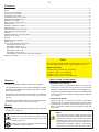
InstallatIon of new mIxer:
Installation and securing:
The mixer must be mounted with rubber feet, which neu-
tralize both shaking and rusting. Spacers can be inserted
under the mixer’s feet, if the oor is not completely even.
The mixer is placed directly on the oor. Foundation bolts
in the oor are only necessary under special conditions,
e.g. on ships
.
Connection to power:
Before the mixer is connected to power, it should be
checked that the voltage and frequency printed on the
machine label is correct in relation to the place of instal-
lation. The machine label is placed at the top right side
of the mixer.
Checking of the direction of rotation of the planetary
head:
Lift up the bowl arms to normal working position
and start the mixer without bowl and tools. Check
the direction of rotation of the planetary head: the
planetary head must rotate in the direction as
stated by the arrow above the planetary head. If
the direction of rotation is wrong, 2 of the phase
wires of the connecting cable must be inverted.
General:
In case of complaints, please contact your supplier.
The guarantee does not cover faults resulting from faulty
operation, overloading and lacking observance of direc-
tions of maintenance.
It should be checked that all loose parts are delivered
with the mixer such as bowl, tools, grease gun and rub-
ber feet
If the mixer has an attachment drive only equipment pro-
duced by Varimixer A/S. must be connected.
safety:
The constant noise level of the workplace of the operator
is lower then 70 dB (A).
The mixer is designed for manufacture of pro-
ducts which do not during processing cause
reactions or emit substances which may be det-
rimental to the user.
Putting your ngers in the bowl while the mixer
is running may cause injuries.
Contents:
OBS:
The mixer is to be connected to power via a plug. The plug
must be dimensioned for min. 16 A, 230/400V~, IP44
When connecting;
1 phase with 0 + earth, use 3 pole plug
2 phases + earth, use 3 pole plug
3 phases + earth, use 4 pole plug
3 phases with 0 + earth, use 5 pole plug
General: ....................................................................................................................................................................................... 2
safety: ....................................................................................................................................................................................... 2
InstallatIon of new mIxer: .................................................................................................................................................................... 2
ConstruCtIon of the mIxer: .................................................................................................................................................................. 3
the mIxers Control panel: ................................................................................................................................................................... 3
the maxImum CapaCIty of the mIxer: ...................................................................................................................................................... 4
reCommended maxImum speeds: ............................................................................................................................................................. 4
operatIon of the mIxer: ...................................................................................................................................................................... 5
Bowl lIftInG and speed Control: .......................................................................................................................................................... 5
tImer funCtIon: .................................................................................................................................................................................... 6
automatIC lowerInG of the Bowl:: ....................................................................................................................................................... 6
pause funCtIon: ................................................................................................................................................................................... 6
the mIxer’s start speed after stop: ..................................................................................................................................................... 6
start-up after stop at hIGh speed: ...................................................................................................................................................... 6
overload: ....................................................................................................................................................................................... 6
software versIon of the Control panel: .............................................................................................................................................. 6
CorreCt use of tools: ......................................................................................................................................................................... 7
CleanInG: ....................................................................................................................................................................................... 7
maIntenanCe and luBrICatIon: .............................................................................................................................................................. 7
Grease types: ...................................................................................................................................................................................... 7
lIst of errors and possIBle solutIon: ................................................................................................................................................. 8
adjustment of speCIal v-Belt: ........................................................................................................................................................ 8
adjustment of Bowl fIxInG: ............................................................................................................................................................ 9
adjustment of Bowl CenterInG: ...................................................................................................................................................... 9
measurInG of Bowl heIGht: ............................................................................................................................................................. 9
adjustment of Bowl heIGht: ........................................................................................................................................................... 9
adjustments of speed (low and hIGh speed Cam dIsks): ................................................................................................................. 11
eleCtrICal dIaGrams: ......................................................................................................................................................................... 12

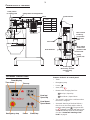
3
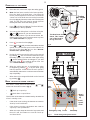
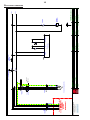
Power supply
Motor relay / thermal
overload relay
Fuse
Safety switch for lid (Optional)
Safety switch
for safety guard
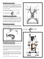
ConstruCtIon of the mIxer:
Size of
mixer
Motor
AR30 1,0 kw
AR40 1,1 kw
AR40P 1,85 kw
AR60 1,85 kw
AR60P 3,0 kw
Motor
Micro switch
for the lower
position of the
bowl arms
Safety
switch (CE)
Micro switch
for the up-
per position
of the bowl
arms
Servo motor
Bowl lift motor
speed indicator
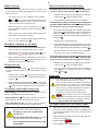
the mIxers Control panel:
Bowl down/
Speed down
Timer/Display
Features of the VL-1S control panel:
• Timer
• Emergency stop
• Pause
• Start / Stop
• Buttons with changing functions:
Bowl up / Speed up
Bowl down / Speed down
• The speed is reduced to a minimum when
the mixer is stopped.
• Automatic lowering of the bowl: When a
time is set on the timer and the mixer is
running, briey press . The green LED
by will ash. The bowl will now be low-
ered automatically when the mixer stops.
See also “Automatic lowering of the
bowl” on page 6.
Bowl up/
Speed up
Time down
Time up
Start/Stop
Emergency stop Pause

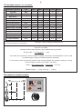
4
30 40
4321
50 60 70 80 90 100%
MINMAX
5
Example: A basic recipe contains 1 kg of solids and 0,6 kg of liquid:
This gives AR =
0,6 kgs x 100
= 60%
1 kg
If for instance it is required to use the maximum capacity of the mixer, the calculated AR = 60% is used
for determining the amount of solids and liquid in the dough:
If a 30 L mixer is used, and a dough with AR = 60% is to be kneaded, the maximum capacity is = 22 kg.
Now the weight of solids in this dough is calculated:
Solids =
Max. capacity x100
=
22 kg x 100
= 13,75 kg
AR + 100 60 + 100
Weight of liquid = 22 kg - 13,75 kg = 8,25 kg
the maxImum CapaCIty of the mIxer:
Local variations in the characteristics of the ingredients can inuence water
absorption, volume and baking characteristics, etc.
* Scraper recommended
** Low speed operation is recommended
Capacities per mix Tool AR30 AR40 AR40P AR60 AR60P
Egg white Whip
3,5 L 6 L
6 L 9 L 9 L
Whipped cream Whip
7,5 L 10 L
10 L 15 L 15 L
Mayonnaise *
Whip
24 L 32 L
32 L 48 L 48 L
Herb butter Beater
17 kg 25 kg
25 kg 45 kg 45 kg
Mashed potatoes * Beater/ Whip
18 kg 23 kg
23 kg 36 kg 36 kg
Bread dough (50%AR) ** Hook
16 kg 22 kg
32 kg 34 kg 46 kg
Bread dough (60%AR) Hook
22 kg 30 kg
34 kg 44 kg 56 kg
Ciabatta dough * (70%AR) Hook
22 kg 30 kg
34 kg 40 kg 50 kg
Mufns * Beater
18 kg 24 kg
24 kg 33 kg 33 kg
Layer cake base Whip
7 kg 10 kg
10 kg 15 kg 15 kg
Meatball mix * Beater
25 kg 30 kg
30 kg 45 kg 45 kg
Icing Beater
20 kg 29 kg
29 kg 40 kg 40 kg
Doughnut (50%AR) Hook
18 kg 25 kg
36 kg 36 kg 54 kg
AR = Absorption Ratio (%AR)
(Liquid in % of solids)
reCommended maxImum speeds:

5
Bowl
up/down
Speed
up/down
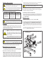
operatIon of the mIxer:
A Place the tool in the bowl. Open the safety guard.
B Note: the bowl arms must be in the lowest position.
Place the bowl in the bowl arms. Check that the
bowl is pushed right back into the arms and that the
“centre ear” of the bowl arms are turning in towards
the mixer (g. 2). Place the mixer tool in the bayonet
shaft. The tap of the tool must be turned right into
the bayonet hole. Close the safety guard.
C Press to lift the bowl (g. 3). The bowl will auto-
matically stop in the top position.
D
You can set the mixing time on the timer using the
and buttons or you can start the mixer
without setting a time. If you do not set a time, the
display will function as a clock that counts up. See
also “Timer function” on page 6.
E Press to start the mixer (g.3).
F Press and until you have reached the desired
speed. You can read the speed on the indicator on
the side of the mixer (g. 2). See also “Recom-
mended max. speeds” (g. 1).
G During the mixing process the mixer can be paused
by pressing . You can now lower the bowl or open
the safety guard. If you start the mixer again using
all the settings will be unchanged. If you start
the mixer using the settings will be reset. See
also “Pause function” on page 6.
H When the mixing process is completed the mixer
is stopped by pressing , or by the timer going
into stop position. In both cases the tool’s speed is
automatically reduced to a minimum and it will then
stop completely.
I When the tool has stopped the bowl can be lowered
by pressing .
Bowl lIftInG and speed Control:
The mixer’s control panel has two buttons: and ,
which both have two functions (g.3):
• Bowl up or speed up
• Bowl down or speed down
The function of the buttons is determined by whether the
mixer is running or not:
• If the mixer is not running, the buttons are used for
“bowl up” and “bowl down”.
• If the mixer is running, the buttons are used for
“speed up” and “speed down”.
• When the mixer stops at the end of a process and
the tool is still, the buttons are used for “bowl up”
and “bowl down”.
The bowl seen from
above, The “centre
ear” of the bowl is
facing the mixer.
”Centre
ear” of the
bowl
Speed indicator
Fig. 3 Bowl lifting and speed control.
Fig 2.
Start/Stop
Emergency stop
Bowl /
Speed
down
Timer/
display
Bowl /
Speed
up
Pause
Time
down
Time up

6
start-up after stop at hIGh speed:
If the emergency stop is activated or the safety guard
has been opened while lifting or lowering the bowl...
• Release the emergency stop (g. 3) by turning it
anticlockwise or close the safety guard.
• Lifting/lowering of the bowl can be reactivated.
If the emergency stop is activated or the safety guard
has been opened while the mixer is running, and you
do not want to start up at the same speed...
• First lower the bowl: Start with releasing the emer-
gency stop or close the safety guard. Then take the
lid off the mixer and press the small red button on
the top side of the control panel while simultaneously
pressing .
• Take the tool out of the bayonet.
•
Close the safety guard, move the bowl arms up to the
top position (empty or with the bowl), start the mixer
and run again to the lowest speed by pressing .
• Stop the machine and secure the mixer’s lid again.
The mixer can now be operated normally.
If the emergency stop is activated or the safety guard
has been opened while the mixer is running at low
speed, and you want to start up at the same speed...
• Release the emergency stop (g. 3) by turning it
anticlockwise or close the safety guard.
• Press and the machine will start at the speed it
was stopped at. The speed can now be regulated
using and
overload:
The mixer must not be overloaded. Sticky and
heavy doughs can overload the mixer.
The overload is further exacerbated if the mixer
tool’s speed is set above the recommended
amount or if the wrong mixer tool is used. Larger
lumps of fat or chilled ingredients must be re-
duced before they are put into the bowl.
Longer time overload will interrupt the mixer.
will be written in the mixer’s display. After
a short while the display will change back to normal
mode and you can start the mixer again as described
in “Start-up after stop at high speed”.
software versIon of the Control panel:
• When you turn on the mixer (power is connected to
the mixer or the emergency stop is released), the
control panel software version can be read on the
mixer’s display:
• It rst displays how many times power has been con-
nected to the mixer.
• It then displays .
• Then it displays the software version.
tImer funCtIon:
The mixer has an optional timer function. If no time is set
on the timer, the display will instead show the time the
mixer has run for.
• The timer can be set to a maximum of 60 minutes.
• and can be used to set the time before start-
ing the mixer or while the mixer is running. The time
can be changed after it has been set.
• When the timer is in use it is important to use to
stop and start the mixer if you do not want the timer
to be reset.
• When the time runs out the speed will be reduced to
a minimum and the mixer will stop.
• You can select automatic bowl lowering when the
timer is in use. Briey press .
automatIC lowerInG of the Bowl:
• If the timer is in use, the bowl can automatically be low-
ered when the time runs out and the mixer stops.
• While the mixer is running, briey press , The
green LED by will ash until the mixer stops.
• When automatic lowering of the bowl is selected it is
important that you use to stop and start the mixer,
otherwise the selection will be reset.
pause funCtIon:
The mixer has a pause button , which should be used
to stop and start the mixer in a process where the timer
is used.
• Stop the mixer using . The timer will continue to
count downwards when you start the mixer again by
pressing .
• When you stop the mixer pressing you can lower
the bowl and open the safety guard. When you press
again, the timer continues to count downwards.
the mIxer’s start speed after stop:
Stop using : The mixer’s speed is reduced to lowest
speed and will start at the lowest speed
Stop by pressing
: The mixer’s speed is reduced to
lowest speed and will start at the lowest speed.
Stop using timer runout: The mixer’s speed is reduced
to lowest speed and will start at the lowest speed.
Stop using emergency stop: The mixer
will start at the speed it was stopped at.
Emergency stop must only be used in
emergencies.
Stop by opening the safety guard: The mixer
will start at the speed it was stopped at.
The safety guard must not be used to stop
the machine!

7
2
until the grease gun feels hard to press or until grease
comes out between the shaft and the pulleys.
The mixer must not be started until the screws
which hold the lid are inserted.
Start the mixer, and set the speed back to low speed.
Stop the mixer and ll the grease gun with new grease
so that it is ready for next time.
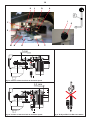
Lubrication of other movable parts:
The movable parts of the bowl arms, the shaft and the
lifting rod must also be lubricated with oil. Remove the
rear covering and lubricate the marked points with an oil
can. (g.4 pkt.2)
Grease types:
Grease for the pulley set shafts: Castrol LMX.
On repair of the planetary head: Grease the toothed wheel
and the toothed rim with Molub Alloy 936SF Heavy or
Castrol Grippa 355, the needle bearings in the planetary
head must not be lubricated with this type of grease. Do
not use any another type of grease than the one stated
here.
On repair of the attachment drive: Fill the attachment drive
with 0.35 L ESSO Fibrax EP 370.
CorreCt use of tools:
The meat mincer must not be used for production
of bread crumbs as this will cause unnecessary
wear and tear on some mixer parts.
Whips should not be struck against hard objects as
e.g. the edge of the bowl. This will make the life of
the tool shorter due to increasing deformity.
Recommended applications for tools:
For production of mashed potatoes the special
wing whip or the whip with thicker wires should be
used, alternatively use the beater and the whip.
CleanInG:
The mixer should be cleaned daily or after use. The mixer
should be cleaned with a soft cloth and clean water.
Sulphonated soaps should be used with caution as they
destroy the mixer’s lubricants.
Never use high pressure cleaning for the
mixer.
Parts made of aluminum should not be used
to strongly acidic, highly alkaline or highly
salty foodstuffs, which may attack aluminum
without coating.
Tools of aluminium must not be washed with
strong alkaline detergents (pH between 5 and 8).
The soap suppliers can recommend the correct type of
soap.
Please note that the plastic safety guard can be
damaged if exposed to high temperatures for a
considerable period. (Max. temperature 65
o
C)
Cleaning of attachment drive: after use of the attachment
drive this should be wiped inside with a soft cloth.
maIntenanCe and luBrICatIon:
The innitely variable gear must be lubricated regularly,
i.e. a lubrication interval of approx. 60 hours of operation.
Lubrication of innitely variable gear:
OBS. Special grease !!(Use the grease gun delivered
together with the mixer). Start the mixer and increase the
speed to approx. 50%. Stop the mixer (use the emergency
stop) and open the lid on the top of the mixer. On the top
of each of the two pulley set shafts is a grease nipple (g.
4 point 1).
Press grease through the grease nipples
g.4 Greasing of innitely variable gear and other
movable parts:
Whip Beater Hook
Cream Cake dough Bread dough
Egg whites Butter cream Dark bread
Mayonnaise Wafe dough and the like
and the like Minced meat
and the like

8
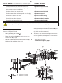
AR30 = 292 mm +/- 3 mm.
(X) AR40/40P = 292 mm +/- 3 mm.
AR60/60P = 305 mm +/- 3 mm.
lIst of errors: possIBle solutIon:
A rattling sound from the closed part of the mixer. Adjustment of special v-belt
The mixer starts “striking” when kneading dough Adjustment of special v-belt
which normally causes no problems.
The mixer changes its speed by itself. Adjustment of special v-belt
The minimum and the maximum speeds are changing. Adjustment of speed.
The bowl is too tight or too loose. Adjustment of bowl xing
The tool hits the sides of the bowl. Adjustment of bowl centering
The tool hits the bottom of the bowl. Adjustment of bowl height
In case of other errors, contact the supplier.
Prior to a possible repair or adjustment, switch off the mixer by disconnecting the power cable.
adjustment of speCIal v-Belt:
The distance (X) is only indicative as it depends on the
tolerance of the special V-belt.
1. Start by tightening the v-belts (
*
).
2. Tighten the special V-belt (A) by moving one or two
washers from (V) to (T).
3. Start the mixer and leave it running while the nut (U)
is tightened. Do not tighten it too much.
4.
On the front pulley set the stud (E) on the varispeed
collar (F) must be placed inside the lower fork (G) and
on the rear pulley set outside the fork for belt tightener
(B), (both must point backwards).
5. Tolerances in the transmission might cause that the
special V-belt (A) is hitting the pins of the pulley sets
when the speed has been adjusted. In such cases the
distance (X) must be reduced.
6. Then follow the section:
“Adjustment of speed” page 11

9
1
2
3
4
adjustment of Bowl fIxInG:
The bowl arms must be raised to normal working posi-
tion. Loosen the counter nuts (1) (g. 5) and remove the
cotterpins (2). Turn the bolts (3) until correct xing of the
bowl is achieved. By turning the bolts out of the extension
tube the xing is increased. Start by turning one of the
bolts half a revolution.
The adjusting diameter shall be measured inside be-
tween the bowl arms (g. 5):
Adjusting diameter Y:
adjustment of Bowl CenterInG:
Loosen the counter nuts (1) (g. 5) and remove the cotter
pins (2). Turn the bolts (3) until the bowl is in the centre of
the mixer. In order not to alter the xing of the bowl, one of
the bolts must be turned out of the extension tube and the
other into the extension tube. Use the at beater to check
that the bowl is correctly centred and turn the planetary
head with your hand before the voltage is connected.
measurInG of Bowl heIGht:
The distance (X) is measured from the bottom side of the
bayonet hole to the surface on the bowl arms on which
the bowl rests (g. 6). The bowl arms must be lifted to
normal working position.
adjustment of Bowl heIGht:
The upper and lower position of the bowl is determined
by micro switch (1) and (2), (g. 6a).
The two mechanical stops consisting of the bolts (3) and
(4) are adjusted so that they will be hit approx. 1 mm
after the micro switch, in case the micro switch should
fail. The upper position of the bowl arms is adjusted by
bending the spring arm on the micro switch (1) forwards
or backwards ,
It is of utmost importance that the stop screw (3) is re-
adjusted afterwards. In the same way the lower position
is adjusted by altering the micro switch (2). It is important
that the micro switch is not altered so much that the bowl
arms can not hit it.
Thereafter the mechanical stop (4) is adjusted.
g. 5 Adjustment of bowl xing and bowl centering
AR30 = 361,8mm
AR40 = 391,3mm
AR60 = 450,4mm
g.6 Measuring of bowl height X:
g.6a Adjustment of bowl height:
AR30 =162 mm.
Bowl height (X): AR40 =162 mm.
AR60 =178 mm
Adjusting diameter Y

10
2-3 mm
1 mm
K
M N H B C
ADL
E
F
G
I
J
g.8 ”Bad position” for the servo motor
g.7a Position of the the V-belt at minimum speed.
g.7b Position of the the V-belt at maximum speed.

11
adjustments of speed (low and hIGh speed Cam dIsks):
Prior to any adjustment the, the bowl must be in its top position and the safety guard must be closed.
Switch off the power to the mixer, this must be done via the emergency stop. Remove the lid of the mixer.
Dismantle shaft for speed regulation: The arm (B) is released from the servo motor shaft by removing the cotter pin
(C) and the pin (D). The arm (B) must not be loosened from the shaft (E).
Loosen the screw (F) and take out the speed indicator (G).
Loosen the screw in the speed indicator clamp (H) and remove the disk with arrow (I)
The manual speed selector handle (J) is placed in the shaft (E) so that it points upwards and forwards.
Release the emergency stop and start the mixer.
Turn the handle for manual adjusting of speed to minimum speed until the distance from the v-belt to the edge of the
planetary head pulley is approximately 1 mm. see g. 7a.
Stop the mixer by pressing emergency stop.
Loosen the two screws on the two cam disks (K) and (L).
Turn the cam disk for minimum speed (K) until it is activating the micro switch. Tighten the screw.
Release the emergency stop and start the mixer.
Turn the handle for manual adjusting of speed to maximum speed until the distance from the v-belt to the edge of the
motor pulley is approximately 3 mm. see g. 7b.
Stop the mixer by pressing emergency stop.
Turn the cam disk for maximum speed (L) until it is activating the micro switch. Tighten the screw.
Remove the manual speed selector handle
Remount the servo motor shaft on the arm (B). It is urgent to make sure that the servo motor is not clamped against the
machine column, the shaft (E) or other parts of the mixer, and that the “bad position” (Fig. 8) for the motor is avoided.
If the servomotor is not positioned correctly (according to the description above), the two screws (M) and (N) that x-
ates the arm on the shaft are loosened and the arm adjusted. Now the handle for manual speed adjustment has to be
mounted again and the cam discs must be adjusted once again.
When the min. and max. speed has been adjusted correctly, the speed indicator clamp, the disk with arrow and the
speed indicator are remounted.
Cam disks for minimum and maximum speed have now been adjusted.

12
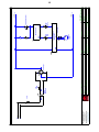
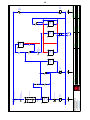
eleCtrICal dIaGrams:
Side
Forrige side:
Næste side:
Antal sider ialt:
Sidst udskrevet:
Sidst rettet:
Siderev.:
Projektrev.:
Godk. (dato/init):
Konstr. (projekt/side):
Tegningsnr.:
Sagsnr.:Projekttitel:
Kunde:
Sidetitel:
Filnavn:
Sideref.:
DCC: Målestok:
VL-1S 5
2313-12-2016
Diagram
PC|SCHEMATIC Automation
30.030-11.03.05 06-09-2017
4
6
01
CE / CE
1:1
1 2 3 4 5 6 7 8
A1A2 A1A2
-K1
/.2
/.6
/6.7
59 59
-R3
/7.1
L3
12
34
56
12
34
56
-F1
/.6
12
34
56
12
34
56
-K1
/.8
PE
U1
V1
W1
M
3
PE
U1
V1
W1
-M1
1 21 2
-S1
1 21 2
L1
L2
L2
/6.1
L1
/6.1
N
-W1 -W2
-F2
230V/1,5A
-X1
PE
1 L1
230VAC/50Hz
2 N
19
-K1
20
21
-F2
22
1 L1
230VAC/50Hz
2 N
19
-K1
20
21
-F2
22
-PCB1
/6.7
9897 9897
-F1
/.2
1314 1314
-K1
/.8
PE Желтый/Зеленый
Синий
Коричневый
Желтый/Зеленый
Коричневый
Основной электродвигатель
черный
серый
черный
серый
Kontaktor
hovedmotor
Relæ 24VDC
Motorværn
Kontaktor
Кнопка аварийной остановки
основной кабель
питания
Motor kabel
предохранитель
FRONT PANEL
Forsyning Hold реле максимального тока
PCB i frontpanel
Kunden leverer
3 x 380 - 480V AC + N + PE
Max. 16A
By kabel
Side
Forrige side:
Næste side:
Antal sider ialt:
Sidst udskrevet:
Sidst rettet:
Siderev.:
Projektrev.:
Godk. (dato/init):
Konstr. (projekt/side):
Tegningsnr.:
Sagsnr.:Projekttitel:
Kunde:
Sidetitel:
Filnavn:
Sideref.:
DCC: Målestok:
VL-1S 5
2313-12-2016
Diagram
PC|SCHEMATIC Automation
30.030-11.03.05 06-09-2017
4
6
01
CE / CE
1:1
1 2 3 4 5 6 7 8
A1A2 A1A2
-K1
/.2
/.6
/6.7
59 59
-R3
/7.1
L3
12
34
56
12
34
56
-F1
/.6
12
34
56
12
34
56
-K1
/.8
PE
U1
V1
W1
M
3
PE
U1
V1
W1
-M1
1 21 2
-S1
1 21 2
L1
L2
L2
/6.1
L1
/6.1
N
-W1 -W2
-F2
230V/1,5A
-X1
PE
1 L1
230VAC/50Hz
2 N
19
-K1
20
21
-F2
22
1 L1
230VAC/50Hz
2 N
19
-K1
20
21
-F2
22
-PCB1
/6.7
9897 9897
-F1
/.2
1314 1314
-K1
/.8
PE
Relay 24VDC
Motor protection
Contaktor
Emergency stop
Brown
Black
Grey
Blue
Yellow/Green
Main
power
cable
Brown
Black
Grey
Yellow/Green
Motor kable
Fuse
FRONT PANEL
Supply Hold
Thermal relay
PCB in front panel
Customer supplied
3 x 380 - 480V AC +N + PE
Max. 16A
Power supply
Contactor
Main Motor

13
Side
Forrige side:
Næste side:
Antal sider ialt:
Sidst udskrevet:
Sidst rettet:
Siderev.:
Projektrev.:
Godk. (dato/init):
Konstr. (projekt/side):
Tegningsnr.:
Sagsnr.:Projekttitel:
Kunde:
Sidetitel:
Filnavn:
Sideref.:
DCC: Målestok:
VL-1S 6
2306-09-2017
Diagram
PC|SCHEMATIC Automation
30.030-11.03.05 06-09-2017
5
7
02
CE / CE
1:1
1 2 3 4 5 6 7 8
BKBU BKBU
-B1
BEBK BEBK
-B2
-F4
24V/8A
1112 1112
-K1
/5.8
7
+24VDC
1
0VDC
10
5
9
3
7
+24VDC
1
0VDC
10
5
9
3
-PCB2
5
Down
6
Down
3
Up
4
Up
5
Down
6
Down
3
Up
4
Up
-PCB1
/5.5
+- +-
-D1
113 113
-R2
/7.2
/7.5
/7.8
4
RD
3 4
RD
3
-S3
24VAC230VAC 24VAC230VAC
-TR1
230VAC/24VAC
L1
/5.8
L2
/5.8
L+ 24VDC
/7.1
L- 0 Volt
/7.1
-F3
M
-M2
24 VDC
-W3
Out
Bowl
Bund
Micro
Bowl
Top
Micro
Fuse
PSB Front panel VL-1S
rectier bridgePower supply
for PCB
termistor
Bowl lift motor
Blue
Brown
Cable for actuator
Down Up
Control unit for bowl lift
Overcurrent relay
Service button for bowl lift
Bowl
Bund
Micro
Bowl
Top
Micro
Fuse
PSB Front panel VL-1S
rectier bridgePower supply
for PCB
termistor
Bowl lift motor
Blue
Brown
Cable for actuator
Down Up
Control unit for bowl lift
Overcurrent relay
Service button for bowl lift

14
Side
Forrige side:
Næste side:
Antal sider ialt:
Sidst udskrevet:
Sidst rettet:
Siderev.:
Projektrev.:
Godk. (dato/init):
Konstr. (projekt/side):
Tegningsnr.:
Sagsnr.:Projekttitel:
Kunde:
Sidetitel:
Filnavn:
Sideref.:
DCC: Målestok:
VL-1S 7
2306-09-2017
Diagram
PC|SCHEMATIC Automation
30.030-11.03.05
02
06-09-2017
6
8
03
CE / CE
1:1
1 2 3 4 5 6 7 8
BE
9596 9596
-F5
21 21
-G3
2324 2324
-K2
1413 1413
-R3
/5.8
1314 1314
-PCB3
VL-1S
/.5,/.7
109 109
-PCB3
VL-1S
/.4,/.6
1615 1615
-PCB3
VL-1S
/.1,/.5
1817 1817
-PCB3
VL-1S
/.4
78 78
-PCB3
VL-1S
/.6,/.8
1112 1112
-PCB3
VL-1S
/.7
91
5
91
5
-R1
/.3
/.5
/.8
102
6
102
6
-R1
/.3
113
7
113
7
-R1
/.3
1413 1413
-R1
/.5
/.8
=
=
/.5
/.8
59 59
-R5
812 812
-R2
/6.7
106 106
-R2
/6.7
1413 1413
-R2
/7.2
/7.5
h1h2 h1h2
-V1
s1s2 s1s2
-V2
L+ 24VDC
/6.8
L- 0 Volt
/6.8
M
-M4
-W5
-W4
/.1
-W4
/.1
13 13 13 13
-G2
VL-1S
VL-1SVL-1S
VL-1S
VL-1S VL-1S
(printed on PCB)
Motor protection
Safety guard
microswitch roll CE
Auxiliary
relay 3
Speed Down 1
Speed Down 1
Frontpanel
Speed Up 1
Speed Up 1
Front panel
Stop
Stop
Front panel
Start
Start
Front panel
Speed Up 2
Speed Up 2
Front panel
Speed Down 2
Speed Down 2
Fron tpanel
Auxiliary
relay 1
Auxiliary
relay 2
Servo
Maximum
Micro
Servo
Minimum
Micro
Servo Motor
Actuator cable
(printed on PCB)
(printed on PCB)
Bowl detection
Cable safety guard
Brown
Blue
Blue
Brown

15
Indhold af Overensstemmelseserklæring, (Maskindirektivet, 2006/42/EC, Bilag II, del A) DK
Contents of the Declaration of conformity for machinery, (Machinery Directive 2006/42/EC, Annex II., sub. A) EN
Inhalt der Konformitätserklärung für Maschinen, (Richtlinie 2006/42/EG, Anhang II, sub A) DE
Contenu de la Déclaration de conformité d’une machine, (Directive Machine 2006/42/CE, Annexe II.A) FR
Inhoud van de verklaring van overeenstemming voor machines, (Richtlijn 2006/42/EC, Bijlage II, onder A) NL
Contenido de la declaración de conformidad sobre máquinas, (Directiva 2006/42/EC, Anexo II, sub A) ES
Fabrikant; Manufacturer; Hersteller; Fabricant; Fabrikant; Fabricante: Varimixer A/S
………………………………………………………………….……
Adresse; Address; Adresse; Adresse; Adres; Dirección: Kirkebjerg Søpark 6, DK-2605 Brøndby, Denmark
……………………………………………………………………….
Navn og adresse på den person, som er bemyndiget til at udarbejde teknisk dossier
Name and address of the person authorised to compile the technical file
Name und Anschrift der Person, die bevollmächtigt ist, die technischen Unterlagen zusammenzustellen
Nom et adresse de la personne autorisée à constituer le dossier technique
naam en adres van degene die gemachtigd is het technisch dossier samen te stellen
nombre y dirección de la persona facultada para elaborar el expediente técnico
Navn; Name; Name; Nom; Naam; Nombre: Kim Jensen
……………………………………………………………………….
Adresse; Address; Adresse; Adresse; Adres; Dirección: Kirkebjerg Søpark 6, DK-2605 Brøndby, Denmark
.........................................................................
Sted, dato; Place, date; Ort, Datum; Lieu, date ; Plaats, datum ; Place, Fecha: Brøndby, 14-03-2018
........................................................................
Erklærer hermed at denne røremaskine
Herewith we declare that this planetary mixer
Erklärt hiermit, dass diese Rührmaschine
Déclare que le batteur-mélangeur ci-dessous
Verklaart hiermede dat Menger
Declaramos que el producto batidora
• er i overensstemmelse med relevante bestemmelser i Maskindirektivet (Direktiv 2006/42/EC)
is in conformity with the relevant provisions of the Machinery Directive (2006/42/EC)
konform ist mit den Bestimmungen der EG-Maschinenrichtlinie (Direktiv 2006/42/EG)
Satisfait à l’ensemble des dispositions pertinentes de la Directive Machines (2006/42/CE)
voldoet aan de bepalingen van de Machinerichtlijn (Richtlijn 2006/42/EC)
corresponde a las exigencias básicas de la Directiva sobre Máquinas (Directiva 2006/42/EC)
• er i overensstemmelse med følgende andre CE-direktiver
is in conformity with the provisions of the following other EC-Directives
konform ist mit den Bestimmungen folgender weiterer EG-Richtlinien
Est conforme aux dispositions des Directives Européennes suivantes
voldoet aan de bepalingen van de volgende andere EG-richtlijnen
está en conformidad con las exigencias de las siguientes directivas de la CE
2014/30/EU ; 1935/2004 ; 10/2011 ; 2023/2006 ; RoHS 2011/65/EU , 822/2013 (DK only)
…………………………………………………………………………………………………………………………………………….....
Endvidere erklæres det
And furthermore, we declare that
Und dass
Et déclare par ailleurs que
En dat
Además declaramos que
• at de følgende (dele af) harmoniserede standarder, er blevet anvendt
the following (parts/clauses of) European harmonised standards have been used
folgende harmonisierte Normen (oder Teile/Klauseln hieraus) zur Anwendung gelangten
Les (parties/articles des) normes européennes harmonisées suivantes ont été utilisées
de volgende (onderdelen/bepalingen van) geharmoniseerde normen/nationale normen zijn toegepast
las siguientes normas armonizadas y normas nacionales (o partes de ellas) fueron aplicadas
EN454:2014 ; EN60204-1:2006; EN12100-2011
……………………………………………………………………………………………………………………………………...
EN61000-6-1:2007; EN61000-6-3:2007
……………………………………………………………………………………………………………………………………...
DS/EN 1672-2 + A1:2009
……………………………………………………………………………………………………………………………………...

16
Innehåll i örsäkran om maskinens överensstämmelse, (Maskindirektivet 2006/42/EG, bilaga 2, A) SV
Contenuto della dichiarazione di conformità per macchine, (Direttiva 2006/42/CE, Allegato II, parte A) IT
Sisukord masina vastavusdeklaratsioon , (Masinadirektiiv 2006/42/EÜ, lisa II, punkt A) ET
Treść Deklaracja zgodności dla maszyn (Dyrektywa maszynowa 2006/42/WE, Załącznik II, pkt A) PL
Sisältö vaatimustenmukaisuusvakuutus koneesta (Konedirektiivi 2006/42/EY, Liite II A) FI
Tillverkare; Fabbricante; Tootja; Producent; Valmistaja: Varimixer A/S
………………………………………………………………….……
Adress; Indirizzo; Aadress; Adres;
Osoite: Kirkebjerg Søpark 6, DK-2605 Brøndby, Denmark
……………………………………………………………………….
Namn och adress till den person som är behörig att ställa samman den tekniska dokumentationen:
Nome e indirizzo della persona autorizzata a costituire il fascicolo tecnico
Tehnilise kausta volitatud koostaja nimi ja aadress
Imię i nazwisko oraz adres osoby upoważnionej do przygotowania dokumentacji technicznej
Henkilön nimi ja osoite, joka on valtuutettu kokoamaan teknisen tiedoston
Namn; Nome e cognome; Nimi; Imię i nazwisko;
Nimi: Kim Jensen
……………………………………………………………………….
Adress; Indirizzo; Aadress; Adres; Osoite: Kirkebjerg Søpark 6, DK-2605 Brøndby, Denmark
.........................................................................
Ort och datum; Luogo e data; Koht, kuupäev; Miejscowość, data; Paikka, aika: Brøndby, 14-03-2018
........................................................................
Försäkrar härmed att denna blandningsmaskin
Con la presente si dichiara che questo mixer planetaria
Deklareerime käesolevaga, et Planetaarmikseri
Niniejszym oświadczamy, że mikser planetarny
vakuuttaa, että tämä mikseri tyyppi
• överensstämmer med tillämpliga bestämmelser i maskindirektivet (2006/42/EG)
is è conforme alle disposizioni della Direttiva Macchine (Direttiva 2006/42/CE)
vastab kehtivatele masinadirektiivi (2006/42/EÜ) nõuetele
spełnia wymagania odpowiednich przepisów dyrektywy maszynowej (2006/42/WE)
on konedirektiivin (2006/42/EY) asiaankuuluvien säännösten mukainen
• överensstämmer med bestämmelser i följande andra EG-direktiv
è conforme alle disposizioni delle seguenti altre direttive CE
vastab järgmiste EÜ direktiivide nõuetele
spełnia wymagania przepisów innych dyrektyw WE
on seuraavien muiden EY-direktiivien säännösten mukainen
2014/30/EU; 1935/2004 ; 10/2011 ; 2023/2006 ; RoHS 2011/65/EU ; 822/2013 (DK only)
…………………………………………………………………………………………………………………………………………………….…...
Vi försäkrar dessutom att
e che
Lisaks ülaltoodule deklareerime, et
Ponadto oświadczamy, że
ja lisäksi vakuuttaa, että
• följande (delar/paragrafer av) europeiska harmoniserade standarder har använts
sono state applicate le seguenti (parti/clausole di) norme armonizzate
kasutatud on järgmisi Euroopa harmoniseeritud standardeid (või nende osi/nõudeid)
zastosowano następujące części/klauzule zharmonizowanych norm europejskich
seuraavia eurooppalaisia yhdenmukaistettuja standardeja (tai niiden osia/kohtia) on sovellettu
EN454:2014 ; EN60204-1:2006; EN12100-2011
……………………………………………………………………………………………………………………………………..................
EN61000-6-1:2007; EN61000-6-3:2007
…… ………………………………………………………………………………………………………………………………...
DS/EN 1672-2 + A1:2009
……………………………………………………………………………………………………………………………………...
-
 1
1
-
 2
2
-
 3
3
-
 4
4
-
 5
5
-
 6
6
-
 7
7
-
 8
8
-
 9
9
-
 10
10
-
 11
11
-
 12
12
-
 13
13
-
 14
14
-
 15
15
-
 16
16


Varimixer AR30-40-60 VL-1S Istruzioni per l'uso
- Categoria
- Miscelatori
- Tipo
- Istruzioni per l'uso