
Via E. Majorana 49 - 48022 Lugo (RA) Tel. + 39 0545 25037 - Fax + 39 0545 32064
E.mail: [email protected] - www.telecogroup.com
WALKIE HG
Antenna TV omnidirezionale 18-10-05
1
10 5 10mm
B
A
B
A
2
1
10 5 10mm
B
A
B
A
2
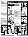
Istruzioni di montaggio
WALKIE HG - Dotata di amplificatore
Banda: 40- 860 MHz
Guadagno Max: BI 8 dB / BIll 24 dB / UHF 26 dB
Alimentazione: 220 Vac / 12-24 Vcc
1) Tagliare il cavo dell' antenna alla lunghezza necessaria e
applicare il connettore come in ( fig. 1 ) facendo attenzione
che nessun filo della calza vada a toccare l'anima del cavo.
2) Introdurre il connettore dell'antenna nell'apposito ingresso
dell' ampificatore AT 36 e collegare quindi gli apparecchi TV
con due spezzoni di cavo.
3) Collegare l'AT 36 con una presa 220 Vac oppure ad una
batteria a 12 ( o 24 ) VoIt, facendo ben attenzione a non
invertire i morsetti + e -
4) Togliere il coperchio C e osservando il televisore regolare la
sensibilità dell'antenna ruotando l'apposita manopola dB +.
FISSAGGIO CON CAVO PASSANTE
1) Sfondare Il foro centrale del supporto A per passaggio del
cavo sul tetto ( fig. 2 ).
2) Posizionare il supporto A sul tetto.
3) Forare il tetto in corrispondenza dei fori del supporto.
4) Spalmare con prodotti siliconici la base del supporto e la
corrispondente superfice del tetto.
5) Fissare con viti il supporto al tetto.
6) Innestare l'antenna e bloccare il collare B con due viti.
7) Sigillare con silicone il passaggio del cavo nel supporto A
NB: Nel caso che l'antenna venga utilizzata solamente a
veicolo fermo é sufficiente fissare Il supporto A al tetto mediante
collante.
FISSAGGIO CON CAVO LATERALE
1) Posizionare il supporto A sul tetto.
2) Forare il tetto in corrispondenza dei fori dei supporto.
3) Spalmare con prodotti siliconici la base del supporto e la
corrispondente superficie del tetto.
4) Fissare con viti il supporto al tetto.
5) Innestare l'antenna e bloccare il collare B con due viti
facendo uscire il cavo dallo scasso laterale.
OPTIONAL
Palo telescopico orientabile H 50 cm. Mod SF 50
Supporto per albero barca ( In acciaio inox ) Mod. ST
Montage- instructies
WALKIE HG - Voorzien van versterker
Band: 40 - 860 MHz
Max. versterking: BI 8 dB / BIlI 24 dB / UHF 26 dB
Voeding: 220 V wisselstroom / 12 -24 V gelijkstroom
1) De antennenkabel op de noodzakelijke lengte afsnijden en
de aansluiting aanbregen zoals in fig. 1; erop letten dat geen
enkele draad van de omvlechting het hart van de kabel raakt.
2) De antenne-aansluiting in de betreffende Ingang van de
AT 36 versterker steken en dan de TV-apparaten met twee
stukjes kabel aansluiten.
3) De AT 36 op een 220 V wisselstroomstopcontact of op
een 12 (o 24 ) Volt accu aansluiten en er goed op letten de
+ en - klemmen niet te verwisselen.
4) Decksel C wegnemen en de gevoeligheid van de antenne
reaelen door de betreffende knop dB+ te draaien, terwijI men het
televisiescherm bekljkt, totdat het beste beeld verkregen wordt.
BEVESTIGING VAN EEN KABEL DOOR HET DAK
1) Het middengat op basis A doorboren om de kabel op het
da door te laten.
2) Basis A op het dak plaatsen.
3) Het dak doorboren ter hoogte van de gaten in de basis.
4) De onderkant van de basis en het overeenkomstige op-
pervlak van het dak met een siliconeproduct insmeren.
5) De basis met schroeven aan het dak bevestigen.
6) De antenne aanbrengen en sluitring B met twee schroeven
vastzetten,
7) Het kabelgat in basis A met silicone afdichten
N.B, In geval de antenne allen gebruikt wordt, als het voertuing
stil staal, is het voldoende basis A met een plakmiddel aan
het dak te bevestigen.
BEVESTIGIN MET EEN KABEL AAN DE ZIJKANT
1) Basis A op het dak plaatsen.
2) Het dak doorboren ter hoogte van de gaten in de basis.
3) De onderkant van de basis en het overeenkomstige op-
pervlak van het met een siliconeproduct insmeren.
4) De basis met schroeven aan het dak bevestigen.
5) De antenne aanbrengen en sluitring B met twee schroeven
vastzette, waarbij met de kabel door de zijgleuf naar buiten
laat komen.
OPTIONAL
Draalbare telescopische mast 50 cm h. SF 50
Basis voor scheepsmast (van roestvrij staal ). Mod. ST
ST
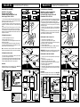
ST
TV
AT 36
12 Vcc
220 Vac
C
TV
TV
AT 36
12 Vcc
220 Vac
C
TV
SF 50
SF 50
Riciclaggio: con lo scopo
di ridurre il più possibile lo
smaltimento dei rifiuti
elettrici ed elettronici, non
gettare quest'apparecchio
a fine vita con gli altri rifiuti
urbani non separati, ma in
un centro di riciclaggio.
Recycling: gooi, om de
afvalverwerking van elek-
trisch en elektronisch afval
zoveel mogelijk te beperken,
dit apparaat aan het einde
van de levensduur niet bij
ander ongescheiden afval
weg, maar lever het in bij
een recyclingcentrum.

Instruction for assembly
WALKIE HG - with amplifier
Reception band: 40 - 860 MHz
Gain Max: BI 8 dB / BIll 24 dB / UHF 26 dB
Power Supply: 220 Vac /12-24 Vcc
1) Cut the antenna cable at the required lenght and appy the
connector as shown in figure 1, being careful that no wire of
the braiding touches the centre core.
2) Insert the antenna connector into the proper entry of
amplifìer AT 36 and then connect the TV sets with two cable
ends.
3) Connect AT 36 to a 220 Vac suppy or to a 12 (or 24) VoIt
battery being careful not to reverse the -and + terminals.
4) Take the lid C off and watch the television and adjust the
sensitivity of the aerial amplifier with control dB+ until the best
reception is obtained.
FITTING WITH SIDE CABLE
1) Position mounting A on to the roof.
2) Mark and drill four holes. ( Fig. 2 )
3) Spread some silicon, on the support base and the corri-
sponding roof surface.
4) Fasten the suppor to the roof by means of the screws.
5) Insert the antenna and lock the clamp B wlth 2 screws,
take the cable out of the side opening.
NB. If the antenna is used only when the vehicle is stationary
fasten the support A to the roof by means of some adhesive.
FITTING WITH CENTRE CABLE
1) Drill out centre in mounting A for cable to pass though.
2) Position mounting A, drill 4 holes.
3) Spread some silicone and screw mounting with 4 screws.
4) Insert cable though centre hole and add some silicone.
5) Mount aerial B and lock with 2 screws onto A.
OPTIONAL
Watertight telescopic roof mountlng H 50 cm. Mod. SF 50
Stalnless steel mast head mounting Mod. ST.
Instructions pour le montage
WALKIE HG - modèle avec amplificateur
Bande de reception: 40 - 860 MHz
Gain Max: BI 8 dB / BIll 24 dB / UHF 26 dB
Alimentation: 220 Vac /12.24 Vcc
1) Couper le câble de l'antenne à la longeur nècèssaire et
monter la fiche coaxiale (voir fig. 1) en faisant attention qu'aucun
fil de la tusse ne vienne en contact avec l'ame du câble.
2) Introduire la fiche de l'antenne dans l'entré appropriée de
l'amplificateur AT 36 et relier aux appareils TV avec deux
rnorceaux de câble
3) Relier l'AT 36 à une prlse 220 Vac ou à une batterie de
12 ou 24 Volts en faisant bien attention à ne pas inverser les
bornes + et -
4) Enlever le couvercle C et en observant la télévislon, régler
la sensibilité de l'antenne en faisant tourner le bouton dB +
jusqu'à obtenir la meuilleure image.
FIXATION AVEC CABLE SUR LA COTE
1) Positionner le support A sur Ie toit:
2) Percer le toit en face des trous du support
3) Etaler des produits au siIicone sur la base du support et
sur la surface du toit, correspondante
4) Fixez le support au toit
5) Installer l'antenne puis bloquer le collier B par deux vis.
Faire sortir le câble à travers la sortie sur le côte
IMPORTANT: si cette antenne n’est utilisée qu’avec le vehicule
en stationement il suffit de coller le support A sur le toit
FIXATION AVEC CABLE PAR LE MILIEU
1) Ouvrir le trou central du support A pour le passage du
cable. ( Fig. 2 )
2) Posltionner le support A sur Ie toit.
3) Percer le toit en face des trous du support
4) Etaler des produits au silicone sur la base du support et
sur la surface du toit correspondante.
5) Visser le support au toit
6) Introduire le câble d'antenne dans le trou correspondant.
7) Fermer hermétiquement le trou du câble dans le support
A avec du silicone
OPTIONAL
Mât Interieur orientable (Livre com.) Haut. 50 cm Mod SF 50
Support pour fixation de haut du mât (en acier Inox) Mod ST
WALKIE HG
Antenne TV omnidirectionnelle
WALKIE HG
Omni-Directional TV Antenna
1
10 5 10mm
B
A
B
A
2
1
10 5 10mm
B
A
B
A
2
ST
ST
TV
AT 36
12 Vcc
220 Vac
C
TV TV
AT 36
12 Vcc
220 Vac
C
TV
SF 50
SF 50
Recyclage: Dans le but de
réduire le plus possible
l’élimination des déchets
électriques et électroniques,
ne pas jeter cet appareil en
fin de vie avec les autres
déchets municipaux non
triés, mais dans un centre
de recyclage.
Recycling: with a view to
reducing disposal of waste
electrical and electronic
equipment as much as
possible, do not throw out
this end of life cycle appliance
together with other unsorted
municipal waste, but make
use of a recycling centre.
-
 1
1
-
 2
2


in altre lingue
- English: Teleco Walkie User manual
- français: Teleco Walkie Manuel utilisateur
- Nederlands: Teleco Walkie Handleiding