
C.C.N. : 80444060
REV. : C
DATE : AUGUST 2008
Ingersoll Rand
System Automation
Operator’s Manual
Before installing or starting this unit for the first
time, this manual should be studied carefully to
obtain a working knowledge of the unit and or the
duties to be performed while operating and
maintaining the unit.
RETAIN THIS MANUAL WITH UNIT. This Technical
manual contains IMPORTANT SAFETY DATA and
should be kept with the unit at all times.
More Than Air. Answers.
Online answers: http://www.air.irco.com
X8I

2
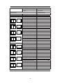
SECTION 1 TABLE OF CONTENTS
SECTION 1 TABLE OF CONTENTS ..........................2
SECTION 2 INTRODUCTION
...................................3
SECTION 3 SAFETY ....................................................3
INSTALLATION .............................................................................3
OPERATION
..................................................................................3
MAINTENANCE AND REPAIR
.................................................3
SECTION 4 COMPRESSOR CONNECTION AND
CONTROL ........................................................................5
COMPRESSOR CONNECTION AND CONTROL ..............5
OPTIONAL CONNECTION METHODS
.................................5
PRESSURE DETECTION AND CONTROL
............................6
X8I MAIN DISPLAY
....................................................................7
SECTION 5 INSTALLATION OVERVIEW .................8
INSTALLATION .............................................................................9
UNIT LOCATION
.......................................................................... 9
POWER SUPPLY
........................................................................... 9
PRESSURE SENSOR LOCATION
.............................................9
PRESSURE SENSOR CONNECTION
....................................10
IRPCB INTERFACE MODULE ................................................10
IR485 AND IRV485 GATEWAY MODULE........................11
IR485 COMMUNICATION PROTOCOL ...............................11
RS485 NETWORK
......................................................................11
SECTION 6 CONTROL FEATURES AND
FUNCTIONS ...................................................................13
STANDARD CONTROL FEATURES AND
FUNCTIONALITY .......................................................................13
STANDARD CONTROL FEATURES AND
FUNCTIONALITY
.......................................................................15
ALTERNATE CONTROL FEATURES AND
FUNCTIONALITY
.......................................................................18
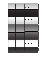
SECTION 7 DISPLAY AND MENU OPERATION ..20
INDICATORS ...............................................................................23
SECTION 8 COMMISSIONING ...............................26
PHYSICAL CHECKS ...................................................................26
PRESSURE DISPLAY
.................................................................26
X8I QUICK SETUP CONFIGURATION
...............................26
OPTIONAL FEATURES AND FUNCTIONS.........................26
SECTION 9 SYSTEM CONFIGURATION ...............27
DISPLAY ITEM STRUCTURE...................................................27
NORMAL OPERATIONAL DISPLAY MENU PAGE P00
27
ACCESSING THE X8I CONFIGURATION SCREENS
........27
USER LEVEL MENUS ................................................................29
SERVICE LEVEL MENUS ..........................................................30
X8I CONFIGURATION SCREENS
.........................................31
X8I COMPRESSOR CONNECTIVITY AND FUNCTIONAL
SETTINGS
.....................................................................................41
SECTION 10 FAULT CODES ....................................46
X8I COMPRESSOR FAULT INDICATIONS, TYPES, AND
CODES: ..........................................................................................46
SECTION 11 — PARTS LIST….. ...............................48
SECTION 12 — DIAGRAMS…... ...............................49
WIRING DIAGRAM……….…….....................................49
CONNECTION DIAGRAM……... ...................................50
XPM-TAC24...................................... ...................................51
X8I COMMISSIONING FORM… ...............................52

3
SECTION 2 INTRODUCTION
The X8I is an advanced system controller designed to
provide safe, reliable, and energy-efficient management
of your compressed air system. The X8I is capable of
controlling up to eight (8) positive displacement air
compressors. The compressors may be fixed speed,
variable speed or multi-step and have electro-pneumatic
or microprocessor based controls. The X8I is uniquely
configurable and customizable to meet the specific needs
of some of the most complex compressed air system.
Additionally, the X8I control network can expand to
include monitoring and control of various compressed air
system components.
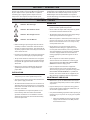
SECTION 3 SAFETY
!
WARNING : Risk of Danger
WARNING : Risk of Electric Shock
!
WARNING : Risk of High Pressure
WARNING : Consult Manual
Before installing or operating the X8I, take time to
carefully read all the instructions contained in this
manual, all compressor manuals, and all manuals of
any other peripheral devices that may be installed or
connected to the unit.
Electricity and compressed air have the potential to
cause severe personal injury or property damage.
The operator should use common sense and good
working practices while operating and maintaining
this system. All applicable codes should be strictly
adhered to.
Maintenance must be performed by adequately
qualified personnel that are equipped with the
proper tools.
INSTALLATION
Installation work must only be carried out by a
competent person under qualified supervision.
A fused isolation switch must be fitted between the
main power supply and the X8I.
The X8I should be mounted in such a location as to
allow operational and maintenance access without
obstruction or hazard and to allow clear visibility of
indicators at all times.
If raised platforms are required to provide access
to the X8I they must not interfere with normal
operation or obstruct access. Platforms and stairs
should be of grid or plate construction with safety
rails on all open sides.
•
•
•
•
•
•
•
•
OPERATION
The X8I must only be operated by competent
personnel under qualified supervision.
Never remove or tamper with safety devices, guards
or insulation materials fitted to the X8I.
The X8I must only be operated at the supply voltage
and frequency for which it is designed.
When main power is switched on, lethal voltages are
present in the electrical circuits and extreme caution
must be exercised whenever it is necessary to carry
out any work on the unit.
Do not open access panels or touch electrical
components while voltage is applied unless it is
necessary for measurements, tests or adjustments.
Such work should be carried out only by a qualified
electrician equipped with the correct tools and
wearing appropriate protection against electrical
hazards.
All air compressors and/or other equipment
connected to the unit should have a warning sign
attached stating ‘THIS UNIT MAY START WITHOUT
WARNING’ next to the display panel.
If an air compressor and/or other equipment
connected to the unit is to be started remotely,
attach warning signs to the equipment stating ‘THIS
UNIT CAN BE STARTED REMOTELY’ in a prominent
location, one on the outside of the equipment, the
other inside the equipment control compartment.
MAINTENANCE AND REPAIR
Maintenance, repairs or modifications must only be
carried out by competent personnel under qualified
supervision.
If replacement parts are required use only genuine
parts from the original equipment manufacturer, or
an alternative approved source.
Carry out the following operations before opening or
removing any access panels or carrying out any work
on the X8I:
Isolate the X8I from the main electrical power
supply. Lock the isolator in the ‘OFF’ position
and remove the fuses.
•
•
•
•
•
•
•
•
•
•
i.

4
Attach a label to the isolator switch and to the
unit stating ‘WORK IN PROGRESS - DO NOT
APPLY VOLTAGE’. Do not switch on electrical
power or attempt to start the X8I if such a
warning label is attached.
Make sure that all instructions concerning operation
and maintenance are strictly followed and that
the complete unit, with all accessories and safety
devices, is kept in good working order.
The accuracy of sensor devices must be checked
on a regular basis. They must be calibrated when
acceptable tolerances are exceeded. Always ensure
any pressure within the compressed air system is
safely vented to atmosphere before attempting to
remove or install a sensor device.
ii.
•
•
The X8I must only be cleaned with a damp cloth,
using mild detergents if necessary. Avoid the use of
any substances containing corrosive acids or alkalis.
Do not paint the control faceplate or obscure any
indicators, controls, instructions or warnings.
•
•

5
SECTION 4 COMPRESSOR CONNECTION AND CONTROL
COMPRESSOR CONNECTION AND
CONTROL
Each air compressor in your system must be interfaced to
the X8I. Interface methods may vary depending on the
compressor type and/or local control configuration. The
following are main methods for interfacing compressors
to the X8I:
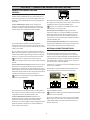
1) The ir-PCB Interface module that is designed to
interface to any positive displacement air compressor
(regardless of make or manufacturer) with an available
control voltage of 12-250V (either 50Hz or 60Hz).
The ir-PCB interface module is installed within the
compressor control area and connected to the X8I using
a six (6) wire cable, (seven (7)-wire cable for Nirvana 7.5 to
15HP (5.5 to 11KW).
Each air compressor must be equipped with an online/
offline pressure regulation system capable of accepting a
remote load/unload signal through a volt-free switching
contact or a single electro-mechanical pressure switch.
Consult the air compressor manual or your air
compressor supplier/specialist for details before installing
the X8I.
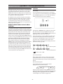
2) The ir-485 Gateway Interface module that is designed
to interface to any Ingersoll Rand Intellisys controlled
(Non-Nirvana) compressor. The X8I communicates to the
ir-485 Gateway via a two wire, RS485 network utilizing the
ir485 protocol. All IR compressors equipped with Intellisys
controllers (Non-Nirvana) require this interface.
All Nirvana Compressors, 20 HP (15KW) and above
require the irV-485 Gateway.
ir-485
The ir-485 Gateway interface module is installed within
the compressor control cabinet and connected to the X8I
using Belden 9841 or equivalent RS485 cable.
3) The irV-485 Gateway Interface module that is
designed to interface to any Ingersoll Rand Nirvana
compressor. The X8I communicates to the irV-485
Gateway via a two wire, RS485 network utilizing the ir485
protocol. All Nirvana Compressors, 20 HP (15KW) and
above, require this interface.
ir - 485
The irV-485 Gateway interface module is installed within
the compressor control cabinet and connected to the X8I
using Belden 9841 or equivalent RS485 cable.
Nirvana 7.5 to 15HP (5.5 to 11KW) connect via the
ir- PCB using seven (7)-wire cable.
4) Direct Connect via RS485 to any Ingersoll Rand
compressor that has an integrated RS485 network port
utilizing the ir485 protocol. The X8I communicates to
these compressors via a two wire, RS485 network. The
compressor is connected to the X8I using Belden 9841 or
equivalent RS485 cable.
4) Special Application Interface uses integration boxes
designed to accommodate various types of compressor
and regulation methods and system monitoring.
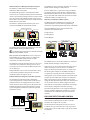
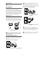
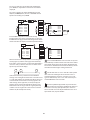
OPTIONAL CONNECTION METHODS
Expansion Module: EXP Box (Option)
As standard the X8I has four direct connect ‘ir-PCB’
terminal connections. This capability can be extended
with the use of an optional EXP Box. The EXP Box will add
another four direct connect ‘ir-PCB’ connection terminals.
This would allow a total of 8 compressors to connected
and controlled via ‘ir-PCB’ integration.
Compressors 1-4 connect via the X8I and Compressors 5-8
connect via the EXP Box
The EXP Box is suitable for wall mounting and must be
located adjacent to the X8I unit (max 33ft or 10m).
Ingersoll Rand
i
4
85
5
8
The EXP Box connects to the X8I controller via a two wire,
dedicated RS485 network
Use Belden 9841 or Equivalent In Grounded Conduit
No Greater Than 33ft (10m)
Up to four air compressors can be connected to the EXP
Box using a 6 or 7 wire cable and a compressor interface
ir-PCB (330ft (100m) max). The ‘ir-PCB’ connections are
identical to the X8I.

6
Remote Compressor Management; EX Box (option)
The EX Box is an ‘EXtension’ to the X8I providing
additional ‘ir-PCB’ connectivity.
The EX Box will typically be used to provide ‘ir-PCB’
connectivity at a remote location beyond the maximum
distance specification of compressors that require ‘ir-PCB’
type connection; 330ft (100m). This effectively expands
the hardwire connection scheme of the ‘ir-PCB” to the full
RS485 distance specification.
The EX box is suitable for wall mounting and can be
located up to 4000ft (1219m) from the X8I unit.
Ingersoll Rand
i
5
4
8
85
4000ft (1219m) max
The EX Box connects to the X8I controller via a two wire,
RS485 network utilizing the IR485 protocol
Use Belden 9841 or Equivalent In Grounded Conduit
No Greater Than 4000ft (1219m)
One (1) or two (2) air compressors can be connected
to the EX Box using a 6-wire cable and a compressor
interface ir-PCB (330ft (100m) max). The ‘ir-PCB’
connections are identical to the X8I.
The EX Box also provides optional ‘local pressure sensor’
connections. The compressor delivery pressure, local
system pressure and air treatment differential pressure
can be displayed.
Multiple EX Boxes can be connected to the X8I as long
as the number of compressors does not exceed the
maximum number of compressors (8).
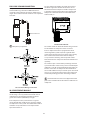
Bolt-On VSD Control Integration: VSD Box (optional)
The VSD Box is intended to provide a method of
system integration for a VSD (Variable Speed Drive) air
compressor that is not equipped with any accessible
means of remote connectivity (such as IR- Nirvana). The
VSD Box will provide required functionality to enable
system integration and efficient control using the X8I
automation system.
From VSD Pressure Transducer
30ft
max
ir-PCB
T
o VSD Pressure Transducer Input
Ingersoll Rand
i
4
85
5
8
The VSD Box connects to the X8I controller via a two wire,
RS485 network utilizing the ir485 protocol
Each air compressor in a system, that requires VSD Box
integration, must be equipped with an individual VSD
Box. Multiple VSD Boxes can be connected to the X8I as
long as the number of compressors does not exceed the
maximum number of compressors (8).
Remote Input & Output: I/O Box (option)
An I/O Box provides additional general purpose I/O
(input/output) for a system enhancing monitoring
capabilities and providing distributed system automation.
Up to two I/O Boxes can be connected to the X8I
controller. Each I/O Box features:
8 Digital Inputs
5 Analog Inputs
6 Relay Outputs
4000ft (1219) max
Ingersoll Rand
i
4
85
5
8
The I/O Box connects to the X8I controller via a two wire,
RS485 network utilizing the ir485 protocol
Digital inputs can be used to monitor switching contact
devices. Each input can be set to act as an Alarm or
High Level Alarm input. Digital inputs can also be used
for metering (for example m3, ft3, kWh) providing an
accumulative count of pulses from a metering device.
Analog inputs can be used to monitor sensor devices (for
example: pressure differential, temperature, dewpoint,
flow, current, power, bearing condition). Each input is
equipped with adjustable high or low level detection that
can be used to activate an Alarm or High Level Alarm.
Relay outputs use ‘Virtual Relay Automation’ technology
and are totally configurable with duel input logic
functions. Relay functions can be assigned utilizing any
status or condition information available on a system
network from any compatible unit connected to the
network.
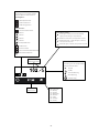
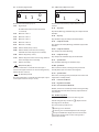
PRESSURE DETECTION AND CONTROL
The X8I utilizes the signal from a 4-20 ma pressure sensor
that is mounted remotely from the X8I in a suitable
location in the compressed air system.
The factory default settings for the pressure sensor is
0–232 PSI (16 bar), but the X8I can accept any pressure
sensor with a 4–20 ma output and a range of up to 8700
PSI (600 bar).

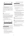
7
X8I MAIN DISPLAY
a
b
c
d
f
g
h
e
Ingersoll Rand
i
85
5
4
8
a
b
c
d
e
a
b
c
a
b
c
1
Keypad and Navigational Keys Functionality
$"$
#$
$ !
%
$"
#!
!%#
'%#
Compressor Status Indicators :
$$%#
%$$%#
!"## "&$(
System Alarms (Warning) :
" %! !"## "%$
#%$!$(""
#$"$!$(""
System Alarms (Warning) :
$%$ ""
$"$ "
User Interface :
(#$"##%"%
(#$"##%"$#
$$$%#
$$&%$ #
#"%$

8
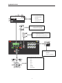
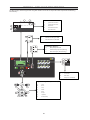
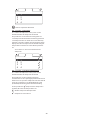
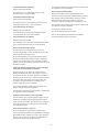
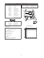
SECTION 5 INSTALLATION OVERVIEW
DRIP LEG
PRESSURE TRANSDUCER
RECEIVER
PRESSURE TRANSDUCER CABLE
2 Conductor Cable, 18 Gauge Stranded
Earth Shielded
No Greater Than 330FT (100M)
24VDC Control Voltage
X8I X05 CONNECTOR
PT CONNECTOR
25 +VDC Pin #3
26 Signal Pin #1
Reference X8I Operations Manual for Pressure
Sensor Connection Details
RS485 Network Cable
Ir-PCB Compressor #1
Control Cable
Ir-PCB Compressor #2
Control Cable
Pressure Transducer Cable
SPECIFICATIONS
Dimensions 13.4” x 9.45” x 6.0”
340mm x 241mm x 152mm
Weight
16.5lb (7.5kg)
Mounting
Wall, 4 x screw fixings
Enclosure
IP65, NEMA 4
Supply 230Vac +/- 10%, 50 Hz
115Vac +/- 10%, 60 Hz
Power
100VA
Temperature 32°F to 115°F
(0°C to 46°C)
Humidity 0% to 95% RH
(non-condensing)
Model X8I
Ingersoll Rand Automation
Supply Voltage Cable
Local Disconnect (Breaker) Box
Fused for 100VA
Power Cable
3 conductor (N, L, E)
(Sized in accordance with local
electrical and safety regulations).
On/Off
Switch
From Air
Compressors
To Plant Air
System
ir-PCB COMPRESSOR CONTROL CABLE
7 Conductor Cable, 18 Gauge, Stranded, Earth Shielded
OR
Single Conductor Wire, 18 Gauge Stranded, Quantity (7)
In Grounded Conduit No Greater Than 330FT (100M)
24VAC Control Voltage
Reference X8I Application and Interconnect Guide For
Wiring Connections Between The X8I, The ir-PCB,
and The Compressor
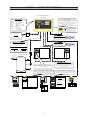
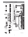
EXP
EXP RS485 Network Cable
The Maximum Number of Compressors Controlled By
The X8I Is Eight (8).
The Maximum Number Of Direct ir-PCB Connections
To The X8I is Four (4)
.
Any Combination Of Compressor Connection Methods
May Be Used As Long As the Maximum Number Of
Compressors (8) Is Not Exceeded.
OPTIONAL
Ingersoll Rand
102
psi
13
24
1
CAP
18:35 #2
57
68
EXP RS485 NETWORK CABLE
Belden 9841 or Equivalent
In Grounded Conduit
No Greater Than 33FT (10)
RS485 NETWORK CABLE
Belden 9841 or Equivalent
In Grounded Conduit
No Greater Than 4000FT (1219M)
EX
Ingersoll
Rand
102 psi
ir-485
Direct To
S3
Ingersoll
Rand
102 psi
OR
Ingersoll
Rand
102 psi
LE
D
1
LE
D
2
ir-PCB
From VSD Pressure
Transducer
To VSD Pressure
Transducer Input
I/O
Ingersoll
Rand
102 psi
VSD
Reference X8I Application and Interconnect Guide For
Wiring Connections Between The X8I, The ir-485 or irV-
485 Gateway and The Compressor, S3 Direct Connects, and
Optional Special Application Interface Boxes
The EXP Will Add Another (4)
Direct ir-PCB connections. This
Would Allow A Total Of (8)
Compressors To Be Connected
And Controlled Via The ir-PCB.
ir-PCB ir-PCB
The RS485 Network is a Serial, Point to Point
Communication Network Refer to the X8I Application and
Interconnect Guide For Wiring Details and Connectivity.
ir-485 Gateway
For All
IR (Non- Nirvana) Compressors
IntelliSys “Red Eye”, SG and SE
irV-485 Gateway
For All
Nirvana Compressors
20HP (15KW) and Above
irV-485
ir-485

9
INSTALLATION
It is recommended that installation and
commissioning be carried out by an authorized and
trained product supplier.
UNIT LOCATION
The X8I can be mounted on a wall using conventional
bolts. The X8I can be located remotely from the
compressors as long as it is within 330 feet (100 meters)
of cable length when connecting compressors directly
with ir-PCB’s. When connecting the X8I over the RS485
communication network the distance is up to 4000 feet
(1219 meters) The X8I must be located within 330 feet
(100 meters) of the system pressure transducer.
POWER SUPPLY
A fused switching isolator must be installed to the main
incoming power supply, external to the X8I. The isolator
must be fitted with a properly sized fuse to provide
adequate protection to the power supply cable used (in
accordance with local electrical and safety regulations).
1
VOLTAGE SELECT
234
4
1
VOLTAGE SELECT
234
4
5
N L E
1234
-4
Power Supply Terminals
Ensure that the voltage select input is properly
jumpered for the incoming power. Default voltage
configuration is 230Vac.
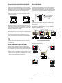
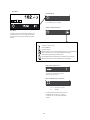
PRESSURE SENSOR LOCATION
The system pressure sensor (P) must be located where
it will see the air pressure that is common to all of the
compressors.
SUPPLY (WET) SIDE PRESSURE CONTROL
1
2
Pressure Sensor Located Before Cleanup Equipment
Dry side pressure will be lower than the system
pressure due to pressure differential losses across air
treatment equipment. The nominal system pressure will
reduce as the air treatment differential pressure increases.
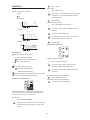
DEMAND (DRY) SIDE PRESSURE CONTROL
1
Pressure Sensor Located After Shared Cleanup
Equipment
1
Pressure Sensor Located After Individual Cleanup
Equipment
Ensure each compressor is equipped with
independent excess pressure shutdown. An increase in
pressure differential across air treatment equipment can
result in excess compressor discharge pressure.
Regular routine monitoring of pressure differential
across air treatment equipment is recommended.

10
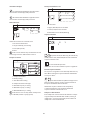
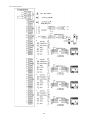
PRESSURE SENSOR CONNECTION
The pressure sensor connects to terminal X05 of the X8I
terminal PCB using a shielded 18 AWG maximum 2-
conductor cable no more than 330 feet (100 meters) in
length. The transducer threads are BPT. It is the equivalent
of ¼” NPT.
Cable Earth Shield
Wire polarity is important.
Pressure Sensor Wiring and Location
IRPCB INTERFACE MODULE
The ir-PCB is designed to interface a compressor with
the X8I using a seven (7)-conductor shielded cable or
individual wires run through grounded conduit no
greater than 330 feet (100 meters) in length.
Each compressor in the system must be assigned a
unique identification number from 1 up to the number
of compressors in the system. The identification number
should be clearly indicated on each compressor for
operational reference.
For each compressor utilizing an ir-PCB, connection to
the X8I the signal wires must be made to the correct
X8I terminals for that compressor number. Compressor
1 should be wired to terminal X01 on the terminal PCB,
Compressor 2 should be wired to terminal X02 on the
terminal PCB, etc.
ir-PCB Interface Module
The ir-PCB is a DIN rail mountable module designed to be
installed within the compressor starter enclosure.
Each air compressor must be equipped with a load/
unload regulation system and, if not regulated with a
single electro-mechanical pressure switch, have a facility
for a remote load/unload control with the ability to
accept a volt-free switching contact input for remote
load/unload. Each air compressor must have Auto Restart
capability.
The ir-PCB accepts a 12V to 250V input voltage detection
system and utilizes universal relay contact control outputs
(250V “CE” / 115V “UL” @ 5A maximum) integrated directly
into the circuits of an air compressor. The ir-PCB avoids
the need for additional relays or remote inputs. The ir-PCB
also acts as an electrical barrier between the compressor
and the X8I providing protection and voltage isolation.
Consult the X8I Interconnect and Application Guide
prior to the installation of the X8I and the ir-PCB to the air
compressor.

11
IR485 AND IRV485 GATEWAY MODULE
The ir-485 and irV-485 Gateways are designed to
interface the Intellisys Controller on the Ingersoll Rand
Compressors and the Nirvana compressors, 20 HP (15KW)
and above, with the X8I via the RS485 Network utilizing
the ir485 protocol. The ir-485 and irV-485 Gateways
are DIN Rail mounted and can be located within the
compressor control gear enclosure or remotely within a
separately enclosure.
ir-485
ir - 485
ir-485 Gateway irV-485 Gateway
The cable used between the X8I and the ir-485 and irV-
485 Gateways is Belden 9841 (or equivalent). It should be
run in grounded conduit and should not be greater than
4000 feet (1219 meters) in length.
The cable used between the ir-485 Gateway and irV-485
Gateways and the Intellisys Controller is included with the
Installation Kit
The cable used between the ir-485 Gateway and the
Intellisys Controller is included with the Installation Kit
Consult the X8I Interconnect and Application Guide
and the ir-485 or irV-485 Gateway Manual prior to the
installation of the X8I and the Compressor Gateway to the
air compressor.
IR485 COMMUNICATION PROTOCOL
ir485 is a unique communication protocol designed
specifically for Compressor and Air System control. ir485
is a Multi-Master vs. a Master–Slave protocol that enables
faster, more effective control of network components.
ir485 also features distributed control capabilities and has
inherent resistance to communication faults due to noise
Note: Follow RS485 Network installation
recommendations.
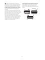
RS485 NETWORK
The X8I is equipped with an RS485 network
communications capability using the ir485 protocol. This
facility can be used for remote connectivity to optional
networked units and modules with ir485 communications
capabilities or compressor controllers equipped with the
ir485 capability.
2
3
2
2
L1
L2
S4
L2
L1
The RS485 Network is a Serial, Point to Point
Communication Network. Refer to the X8I Application
and Interconnect Guide For Wiring Details and
Connectivity.
The following example details the “correct” method of
wiring the RS485 Network
Ingersoll Rand
i
4
85
5
8
4000ft (1219m) max
Correct RS485 Network Example
The following example details the “incorrect” method of
wiring the RS485 Network
Ingersoll
Rand
i
Ingersoll Rand
i
5
4
8
85
Ingersoll
Rand
i
Ingersoll
Rand
i
Ingersoll
Rand
i
Incorrect RS485 Network Example

12
RS485 data communications and other low
voltage signals can be subject to electrical interference.
This potential can result in intermittent malfunction
or anomaly that is difficult to diagnose. To avoid this
possibility always use earth shielded cables, securely
bonded to a known good earth at one end. In addition,
give careful consideration to cable routing during
installation.
a) Never route an RS485 data communications or low
voltage signal cable alongside a high voltage or 3-phase
power supply cable. If it is necessary to cross the path of a
power supply cable(s), always cross at a right angle.
b) If it is necessary to follow the route of power
supply cables for a short distance (for example: from a
compressor X8I to a wall along a suspended cable tray)
attach the RS485 or signal cable on the outside of an
earthed cable tray such that the cable tray forms an
earthed electrical interference shield.
c) Where possible, never route an RS485 or signal cable
near to equipment or devices that may be a source of
electrical interference (for example: 3-phase power
supply transformer, high voltage switchgear unit,
frequency inverter drive module, radio communications
antenna).

13
SECTION 6 CONTROL FEATURES AND FUNCTIONS
STANDARD CONTROL FEATURES AND
FUNCTIONALITY
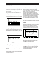
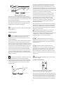
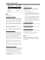
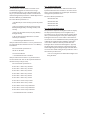
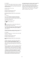
PRESSURE CONTROL
Pressure control is achieved by maintaining the system pressure
within an acceptable range, or pressure band, which is defined and
programmed by the user. Pressure will rise in the band when system
demand is less than the loaded compressor’s output. Pressure will
fall in the band when system demand is greater than the loaded
compressor’s output.
Simply stated, pressure control is achieved by unloading and
loading compressors to closely match compressor output with
system demand within a specified pressure band defined by PL and
PH. See Figure 1.
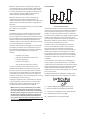
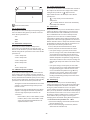
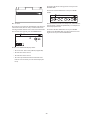
Variable speed compressors also operate within the pressure band
and actively match compressor output with system demand by
speeding up and slowing down around a target pressure defined by
the exact midpoint of the pressure band defined by PT. See Figure 2.
a
b
Figure 1 — Typical System Pressure vs. Time
As pressure rises to point “a”, the compressor will unload
based on the sequencing algorithm. System pressure is
then allowed to decrease due to the drop in supply until
point “b” is reached. Once point “b” is reached, the X8I will
load the next compressor in the sequence to match the
air demand. This cycle will repeat as long as the X8I is able
to keep the system air pressure between PH and PL.
Figure 2 — Typical VSD Pressure Control vs. Time
The variable speed compressors in the system will run
on their target pressure and smooth out the variations in
system pressure. This assumes that system demand does
not vary more than the capacity of the variable speed
compressor.
A variable speed compressor will be included in the
load/unload sequence and be controlled exactly as a
fixed speed machine with the exception of speed control
to maintain target pressure.
ANTI-CYCLING CONTROL
The most efficient way to utilize most air compressors is
either fully loaded or off, with the exception of variable
speed compressors which can operate efficiently at
reduced loading. Compressor cycling (start-load-unload-
stop, etc.) is essential to maintain pressure control.
Excessive cycling, however, can result in poor compressor
efficiency as well as increased maintenance.
Anti-cycling control is incorporated to help ensure
that only the compressors that are actually required
are started and operating while all others are kept off.
Anti-cycling control includes a pressure tolerance range
or band, defined by the user, which is outside of the
primary pressure band. Inside the tolerance band, an
active control algorithm continually analyzes pressure
dynamics to determine the last possible second to add or
cycle another compressor into the system. This control is
further enhanced by the ability to fine tune the tolerance
band settings and algorithm processing time (Damping).
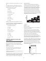
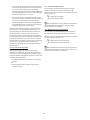
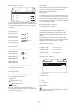
TOLERANCE
Tolerance is a user adjustable setting that determines
how far above the PH setpoint and below the PL setpoint
system pressure will be allowed to stray. Tolerance
keeps the X8I from overcompensating in the event of
a temporary significant increase or decrease in system
demand.
Figure 3 — Tolerance in Relation to PH and PL
Tolerance (TO) is expressed as a pressure defining the
width of the band above PH and below PL in which
energy efficient control will be in effect.
When system pressure is in the tolerance band, the
X8I will continuously calculate the moment at which
compressors will be loaded or unloaded based on the rate
of change of system pressure. When the system pressure
strays outside of the tolerance band, the X8I will abandon
energy efficiency and begin to protect the system air
pressure by loading or unloading the compressors.
Loading will be delay controlled.

14
When the compressed air system storage is relatively
small compared to the system demand, and fluctuations
are large and quick, the tolerance band setting should
be increased to maintain energy efficient operation and
avoid a situation in which multiple compressors are
loaded just to be unloaded moments later.
When the compressed air system is relatively large
compared to system demand and fluctuations are
smaller and slower, the tolerance band can be reduced to
improve pressure control and maintain energy efficient
operation.
The factory default setting for tolerance is 3.0 PSI (0.2Bar).
This setting is user adjustable.
DAMPING
Any time the pressure is within the Tolerance band the
Anti-Cycling algorithm is active, sampling the rate of
pressure change and calculating when to load or unload
the next compressor. The damping (DA) setting is a user
adjustable setpoint that determines how quickly the
controller samples and recalculates, effectively speeding
up or slowing down the reaction time.
The X8I’s factory default DA setting of “1” is adequate for
the majority of compressed air systems but may need
to be adjusted in the following circumstances involving
aggressive and disproportionate system pressure
changes:
Inadequate air storage
High pressure differential across the air
treatment equipment
Incorrectly sized piping
Slow or delayed compressor response
In these circumstances, the X8I may overreact and
attempt to load additional compressors that may not
be necessary if the system was given time to allow the
system pressure to stabilize after the initial compressor
is given time to load. If the tolerance has already been
increased and the X8I is still overreacting, then increasing
the damping factor is the next step.
Damping is adjustable and is scaled from 0.1 to 10 with
a factory default of 1. A factor of 0.1 is a reaction time
10 times faster than the default and a factor of 10 is a
reaction time 10 times slower than the default.
NOTE: There are many variables that go into deter-
mining the stability and control of the system pres-
sure, only some of which are able to be controlled by
the X8I. System storage, air compressor capacity, and
air demand all need to be analyzed by experienced
professionals to determine the best installation for
your system. Tolerance (TO) and damping (DA) can be
used for minor tuning of the system.
•
•
•
•
SYSTEM VOLUME
-
Assorted Receiver Tanks
System volume defines how fast system pressure will rise
or fall in reaction to either increased/decreased demand
or increased/decreased supply. The larger the system
volume, the slower the pressure changes in relation to
increased/decreased demand or supply. Adequate system
volume enables effective pressure control and avoids
system over-pressurization in response to abrupt pressure
fluctuations. Adequate system volume is created by
correctly sizing and utilizing air receivers.
The most accurate way to determine the size of air
receivers or the additional volume required would
be to measure the size and duration of the largest
demand event that occurs in the system, then size the
volume large enough to ride through the event with
an acceptable decrease in system pressure. Sizing the
volume for the worst event will ensure system stability
and effective control over all other normal operating
conditions.
If measurement is not available, then estimating the
largest event is a reasonable alternative. For example,
assume that the largest demand event could be equal to
the loss of the largest operating air compressor. System
volume would be sized to allow time for a back-up
compressor to be started and loaded with an acceptable
decrease in pressure.
The following formula determines the recommended
minimum storage volume for a compressed air system:
V — “Volume of Required Storage” (Gal, Ft3, m3, L)
T — “Time to Start Back-up Compressor” (Minutes)
C — “Lost Capacity of Compressed Air” (CFM, m3/min)
Pa — “Atmospheric pressure” (PSIa, BAR)
ΔP — “Allowable Pressure Drop” (PSI, BAR)

15
Example 1: Find Required Storage Volume in Ft3 and US
Gal.
(4) - 100 Hp Compressors at 450 CFM (12.7 m3) each /
15 seconds to start and load a compressor. 5PSIG is the
maximum allowable pressure drop.
T=15 Seconds (.25 minute)
C=450 ft3
Pa = 14.5 PSI
Delta P = 5 PSI
V = [.25 x (450 x 14.5)]/5
V = (.25 x 6525)/5
V = 1631/5
V = 326 Ft3
1 ft3 = 7.48 Gal
Gal= 326 Ft3 x 7.48
Gal = 2440
Example 2: Find Required Storage Volume in m3 and L.
(4) - 100 Hp Compressors at 450 CFM (12.7 m3) each / 15
seconds to start and load a compressor. 0.34 BAR is the
maximum allowable pressure drop.
T=15 Seconds (.25 minute)
C=12.7 m3
Pa = 1BAR
Delta P = .34 BAR
V = [.25 x (12.7 x 1)]/.34
V = (.25 x 12.7)/.34
V = 3.2/.34
V = 9.33m3
1m3 = 1000 L
L= 9.33 m3 x 1000
L = 933
STANDARD CONTROL FEATURES AND
FUNCTIONALITY
STANDARD SEQUENCE CONTROL STRATEGIES
The standard configuration of the X8I provides ENER
(Energy Control) sequence control strategy, Priority
Settings, Table Selection, Pressure Schedule, and Pre-fill
operation.
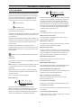
ENER: Energy Control Mode
The primary function of Energy Control mode is to:
1/ Dynamically match compressed air supply with
compressed air demand.
2/ Utilize the most energy efficient set/combination of air
compressors to achieve 1/.
Energy Control mode is designed to manage systems that
include compressors of different capacities and different
air compressor types (fixed speed, variable speed and
variable capacity) in any combination or configuration.
Control and Rotation:
Compressor control and utilization is dynamically
automated with adaptive control logic and therefore
does not follow pre-determined schedules, rotation
configurations or time intervals. Energy Control mode
can, however be operator influenced by the Priority
functionality which is discussed later in this manual.
Energy Control mode is enabled by the ability of the
X8I to process individual compressor capacity, variable
capacity capabilities, and changes in system pressure to
dynamically implement and continuously review ‘best fit’
configurations as demand variations occur.
2
4
1
1
2
1
1: Demand
2: Supply
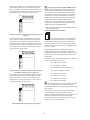
PRIORITY SETTINGS
The sequence assignment pattern can be modified by
using the priority settings.
Priority settings can be used to modify the rotation
sequence assignments. Compressors can be assigned
a priority of 1 to 8, where 1 is the highest priority. Any
compressor can be assigned any priority and any number
of compressors can share the same priority.
Priorities allow you to set up rotation groups. All
compressors that have the same priority number will
rotate inside their own group. The group with the highest
priority will always be in the front of the sequence.
For example, in a four compressor system including one
variable speed compressor in the compressor 1 position
you may want the variable speed compressor to always
be in the Lead position. By assigning compressor 1 a
priority of 1 and the other three compressors a priority
of 2, the variable speed compressor will always remain at
the front of the sequence:
1 2 3 4
1
2
3
4
AC
AC
AC
AC
Compressor 1 has priority 1, all other compressors have
priority 2

16
In another example, there is a four compressor system
that includes a compressor in the compressor 4 spot
that is used only as an emergency backup compressor.
To accomplish this, simply assign compressor 4 a lower
priority than any other compressor in the system:
1
1
Compressor 4 has priority 2, all other compressors have
priority 1
In a third example, there is a four compressor system
that includes a variable speed compressor designated
compressor 1 and a fixed speed compressor that is an
emergency backup assigned as compressor 4. To ensure
that compressor 1 is always at the front of the sequence
and compressor 4 is always at the end of the sequence,
set the priority as shown below:
1
1
Compressor 1 has priority 1, compressor 4 has priority 3
and all other compressors have priority 2
A last example involves another four compressor system
that will be assigned into two independently rotation
groups. Compressors 1 and 2 are given priority 1 and
compressors 3 and 4 are given priority 2. This results in
the rotation sequence shown below:
1
1
Two independently rotating compressor groups
Priority control will also work with ENER control
mode. Recall that ENER control automatically selects
the most efficient set of compressors to dynamically
match compressed air demand. Priority will force the
X8I controller to select from all “priority 1” compressors
and make sure that they are loaded in the sequence
before utilizing any priority 2 compressors. All priority
2 compressors must be utilized before priority 3
compressors can be loaded and so on. Priority allows
a system to be segregated to backup and primary use
compressors when using ENER control.
Note: Using the Priority function with ENER Control can
affect system efficiency.
TABLES AND THE PRESSURE SCHEDULE
The X8I operates based on settings that are
configured into one of three tables. Each table defines
the operational settings and sequence control mode
of the X8I. The X8I can be instructed to change among
the tables at any time based on the configuration of the
pressure schedule.
This functionality allows the X8I to switch among
multiple different system configurations without any
disruption to control. This is particularly useful in the case
of shift changes, or weekends when the system is to be
deactivated.
Each table consists of the following parameters which can
be set independently in each table:
PH – High Pressure Setpoint
PL – Low Pressure Setpoint
Pm – Minimum pressure warning level
SQ – Sequence Rotation Strategy
01 – Compressor 1 Priority
02 – Compressor 2 Priority
03 – Compressor 3 Priority
04 – Compressor 4 Priority
The “maximum” pressure fault level and the rotation
interval, or rotation time, are set independently in a
configuration menu and are unchanging regardless of the
table selected.
When the X8I is instructed to change between tables,
it will not abruptly change the system operating
parameters. The X8I will adjust the system target pressure
upward or downward to the next table’s settings.
This transition will occur gradually to preserve energy
efficiency and safe, reliable control:
•
•
•
•
•
•
•
•

17
C
Changing Target Pressures
The time the system is allotted to change the target
pressure is known as the Pressure Change Time (PC). This
is a value that is adjustable in the system settings screen.
See the Quick Setup Manual.
If the X8I is able to complete the transition in less time
than is allotted without threatening energy efficiency
then PC will be automatically shortened.
An aggressively short time setting will compromise
energy efficiency.
PRESSURE SCHEDULE
The X8I is equipped with a real-time clock feature
and pressure schedule functionality. The pressure
schedule function can be used to provide enhanced
system automation.
The pressure schedule consists of 28 individual settings
that instruct the system to change from one table to
another, or put the system into standby mode dependent
on the time of day and the day of the week. The pressure
schedule will cycle from 00:00 hours Monday (day #1) to
23:59 hours on Sunday (day #7) each calendar week.
The pressure schedule has the capability of changing
tables based on the time of day, once each day, or once
each day except weekends. Please see the Quick Setup
Manual for detailed information on how to configure the
pressure schedule.
The Prefill feature provides a controlled and energy
efficient method of increasing pressure to normal
operating levels at system start. This feature avoids the
inefficient potential for all available system compressors
to start and load before pressure reaches the normal
operating level.
At system start (manual start or automated start from
standby) the X8I will only load compressors that have
been pre-determined for prefill operation, for a pre-set
period of time. The prefill time (PT) can be adjusted to suit
system characteristics. The aim is to increase pressure to
normal operational levels, using only the pre-determined
compressors, prior to the prefill time expiring.
If normal operational pressure is reached prior to the
set prefill time, the prefill function will automatically
cease and normal operational control begin. If normal
operational pressure is not reached by the end of
the prefill time the P4 will utilize as many available
compressors as required to achieve normal operational
pressure as quickly as possible. Normal operational
control will then begin.
Three prefill modes are available. ‘Backup’ and ‘Standard’
modes require compressor pre-selection and function in
the same way; differing only in response to a failure, or
loss, of a prefill compressor. Automatic mode requires no
compressor pre-selection.
Backup Mode: Compressor(s) can be pre-selected
as ‘Primary Prefill’ compressor(s) or ‘Backup Prefill’
compressor(s). If a primary prefill compressor experiences
a shutdown, or is stopped, a pre-defined backup
compressor replaces it and prefill continues.
Standard Mode: If one or more of the pre-
defined prefill compressors experiences a shutdown, or
is stopped, the prefill function is cancelled and normal
operation begins.
A
Automatic Mode: No Prefill compressor
selection is necessary; any selection set is ignored. The
management unit automatically selects compressor(s)
dynamically to achieve pressure in accordance with
the set Prefill time. If a compressor is stopped, or shuts
down, it is automatically substituted with an alternative
compressor.
To manually skip Prefill mode, press and hold Start
for several seconds.
Insufficient Capacity Alarm
The X8I is equipped with a dedicated ‘Insufficient
Capacity’ Advisory Alarm (Warning) indication.
This indication will illuminate if all available compressors
are loaded and system pressure is continuing to decrease.
The indication will generally occur prior to any set low
pressure Alarm (Warning) and is intended to provide an
advanced warning of a potential ‘Low Pressure’ situation.

18
The ‘Insufficient Capacity’ advisory alarm is intended as an
advanced warning and is not recorded in the fault history
log but is included as a Group Alarm (Warning), or Group
Fault item.
‘Insufficient Capacity’ is available as a dedicated data
communications item.
The ‘Insufficient Capacity’ advisory alarm function
can be de-activated. In this instance the unit’s Alarm
indicator will still illuminate but no group alarm, group
fault, or a remote indication is generated.
Restricted Capacity Alarm
The X8I is equipped with a dedicated ‘Restricted Capacity’
Advisory Alarm (Warning) indication.
This indication will flash if all available compressors are
loaded and further capacity is required but one or more,
compressors are: 21
a) inhibited from use in a ‘Table’ priority setting
b) inhibited from use by the short-term Service/
Maintenance function
c) inhibited from use in the long term maintenance menu.
The ‘Restricted Capacity’ advisory alarm is intended to
indicate that all available compressors are already loaded
and further capacity is required but one or more, system
compressor(s) have been restricted from use.
The ‘Restricted Capacity’ advisory alarm is not recorded
in the fault history log but is included as a Group Alarm
(Warning), or Group Fault item.
‘Restricted Capacity’ is available as a dedicated data
communications item.
The ‘Restricted Capacity’ advisory alarm function can
be de-activated. In this instance the unit’s Alarm indicator
will still flash but no group alarm, group fault, or a remote
indication is generated.
ALTERNATE CONTROL FEATURES AND
FUNCTIONALITY
Energy Control Mode (ENER) is the STANDARD control
mode of the X8I. Alternate control strategies of the X8I are
the basic FILO (First in / Last Out) and EHR (Equal Hours
Run) EHR
FILO: TIMER ROTATION MODE
The primary function of Timer Rotation mode is to
efficiently operate a compressed air system consisting of
fixed capacity output compressors. The routine rotation
assignments can be modified using ‘Priority’ settings
to accommodate for a differentially sized or variable
capacity output compressor(s).
Rotation:
Each time the rotation interval elapses, or the rotation
time is reached, a sequence rotation occurs and the
sequence assignment for each compressor is re-arranged.
The compressor that was assigned for duty (A) is re-
assigned as last standby (D) and all other compressor
assignments are incremented by one.
1
1
The sequence assignment pattern can be modified by
‘Priority’ settings.
Tables; Priority Settings
Control:
Compressors are utilized, in response to changing
demand, using a ‘FILO’ (First In, Last Out) strategy.
The ‘duty’ compressor (A) is utilized first followed by (B)
if demand is greater than the output capacity of (A). As
demand increases (C) is utilized followed by (D) if demand
increases further.
As demand reduces (D) is the first compressor to be
unloaded, followed by (C) and then (B) if demand
continues to reduce.
The last compressor to be unloaded, if demand reduces
significantly, is (A). The compressor assigned as (A) in
the sequence is the first to be loaded and the last to be
unloaded.

19
SEQUENCE ROTATION EVENTS
A sequence rotation event can be triggered in the
following ways: a periodic interval, a pre-determined
time each day, or a pre-determined time day and time
each week. Please refer to the Quick Setup Manual to
determine how to configure the rotation events.
EQUAL HOURS RUN MODE
The primary function of EHR mode is to keep the
running hours of all compressors in the system as close
as possible. This provides the opportunity to service
all of the compressors at the same time, given that the
expected service interval for the compressors is similar.
EHR is not an energy efficient focused mode of
operation.
Each time the rotation interval elapses, or the rotation
time is reached, the sequence order of compressors is
reviewed and re-arranged dependant on the running
hours recorded for each compressor. The compressor with
the least recorded running hours is assigned as the ‘duty’
compressor, the compressor with the greatest recorded
running hours is assigned as the ‘last standby’ compressor.
For systems with more than two compressors, the
remaining compressor(s) are assigned in accordance with
there recorded running hours in the same way.
Example: The compressors in a four compressor system
have the following recorded running hours when a
rotation event occurs:
Compressor 1 = 2200 hours
Compressor 2 = 2150 hours
Compressor 3 = 2020 hours
Compressor 4 = 2180 hours
The new sequence order after the rotation event would
be:
Compressor 1 = D
Compressor 2 = B
Compressor 3 = A
Compressor 4 = C
Compressor 3, which has the fewest running hours, will
now be utilized more frequently in the new sequence,
allowing running hours to accumulate at a faster rate.
The X8I continuously monitors the running status of each
compressor and calculates the accumulated running
hours. These readings are viewable and adjustable
in the X8I C01 setting screens. The X8I will use these
values during EHR mode. The running hours on the X8I
should be routinely checked to see that they match the
compressors’ local calculations, and adjusted if necessary.
•
•
•
•
•
•
•
•
If a compressor is operated independently from
the X8I the running hours record may not be accurately
updated.
The running hours meter display on most
compressors are intended for approximate service
interval indication only and may deviate in accuracy over
a period of time.
Control:
Compressors are utilized, in response to changing
demand, using a ‘FILO’ (First In, Last Out) strategy. The
‘duty’ compressor (A) is utilized first followed by (B) if
demand is greater than the output capacity of (A).
As demand increases (C) is utilized followed by (D) if
demand increases further. As demand reduces (D) is the
first compressor to be unloaded, followed by (C) and then
(B) if demand continuous to reduce.
The last compressor to be unloaded, if demand reduces
significantly, is (A). The compressor assigned as (A) in
the sequence is the first to be loaded and the last to be
unloaded.

20
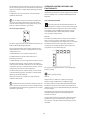
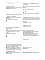
SECTION 7 DISPLAY AND MENU OPERATION
The Main Display and the keypad and navigation buttons on the X8I are depicted below and provide the following
functionality:
a
b
c
d
f
g
h
e
Ingersoll Rand
i
85
5
4
8
1
Keypad and Navigational Keys Functionality
$"$
#$
$ !
%
$"
#!
!%#
'%#
Compressor Status Indicators :
$$%#
%$$%#
!"## "&$(
System Alarms (Warning) :
" %! !"## "%$
#%$!$(""
#$"$!$(""
System Alarms (Warning) :
$%$ ""
$"$ "
User Interface :
(#$"##%"%
(#$"##%"$#
$$$%#
$$&%$ #
#"%$
La pagina si sta caricando...
La pagina si sta caricando...
La pagina si sta caricando...
La pagina si sta caricando...
La pagina si sta caricando...
La pagina si sta caricando...
La pagina si sta caricando...
La pagina si sta caricando...
La pagina si sta caricando...
La pagina si sta caricando...
La pagina si sta caricando...
La pagina si sta caricando...
La pagina si sta caricando...
La pagina si sta caricando...
La pagina si sta caricando...
La pagina si sta caricando...
La pagina si sta caricando...
La pagina si sta caricando...
La pagina si sta caricando...
La pagina si sta caricando...
La pagina si sta caricando...
La pagina si sta caricando...
La pagina si sta caricando...
La pagina si sta caricando...
La pagina si sta caricando...
La pagina si sta caricando...
La pagina si sta caricando...
La pagina si sta caricando...
La pagina si sta caricando...
La pagina si sta caricando...
La pagina si sta caricando...
La pagina si sta caricando...
La pagina si sta caricando...
La pagina si sta caricando...
La pagina si sta caricando...
La pagina si sta caricando...
La pagina si sta caricando...
La pagina si sta caricando...
La pagina si sta caricando...
La pagina si sta caricando...
La pagina si sta caricando...
La pagina si sta caricando...
La pagina si sta caricando...
La pagina si sta caricando...
La pagina si sta caricando...
La pagina si sta caricando...
La pagina si sta caricando...
La pagina si sta caricando...
La pagina si sta caricando...
La pagina si sta caricando...
La pagina si sta caricando...
La pagina si sta caricando...
La pagina si sta caricando...
La pagina si sta caricando...
La pagina si sta caricando...
La pagina si sta caricando...
La pagina si sta caricando...
La pagina si sta caricando...
La pagina si sta caricando...
La pagina si sta caricando...
La pagina si sta caricando...
La pagina si sta caricando...
La pagina si sta caricando...
La pagina si sta caricando...
La pagina si sta caricando...
La pagina si sta caricando...
La pagina si sta caricando...
La pagina si sta caricando...
La pagina si sta caricando...
La pagina si sta caricando...
La pagina si sta caricando...
La pagina si sta caricando...
La pagina si sta caricando...
La pagina si sta caricando...
La pagina si sta caricando...
La pagina si sta caricando...
La pagina si sta caricando...
La pagina si sta caricando...
La pagina si sta caricando...
La pagina si sta caricando...
La pagina si sta caricando...
La pagina si sta caricando...
La pagina si sta caricando...
La pagina si sta caricando...
La pagina si sta caricando...
La pagina si sta caricando...
La pagina si sta caricando...
La pagina si sta caricando...
La pagina si sta caricando...
La pagina si sta caricando...
La pagina si sta caricando...
La pagina si sta caricando...
La pagina si sta caricando...
La pagina si sta caricando...
La pagina si sta caricando...
La pagina si sta caricando...
La pagina si sta caricando...
La pagina si sta caricando...
La pagina si sta caricando...
La pagina si sta caricando...
La pagina si sta caricando...
La pagina si sta caricando...
La pagina si sta caricando...
La pagina si sta caricando...
La pagina si sta caricando...
La pagina si sta caricando...
La pagina si sta caricando...
La pagina si sta caricando...
La pagina si sta caricando...
La pagina si sta caricando...
La pagina si sta caricando...
La pagina si sta caricando...
La pagina si sta caricando...
La pagina si sta caricando...
La pagina si sta caricando...
La pagina si sta caricando...
La pagina si sta caricando...
La pagina si sta caricando...
La pagina si sta caricando...
La pagina si sta caricando...
La pagina si sta caricando...
La pagina si sta caricando...
La pagina si sta caricando...
La pagina si sta caricando...
La pagina si sta caricando...
La pagina si sta caricando...
La pagina si sta caricando...
La pagina si sta caricando...
La pagina si sta caricando...
La pagina si sta caricando...
La pagina si sta caricando...
La pagina si sta caricando...
La pagina si sta caricando...
La pagina si sta caricando...
La pagina si sta caricando...
La pagina si sta caricando...
La pagina si sta caricando...
La pagina si sta caricando...
La pagina si sta caricando...
La pagina si sta caricando...
La pagina si sta caricando...
La pagina si sta caricando...
La pagina si sta caricando...
La pagina si sta caricando...
La pagina si sta caricando...
La pagina si sta caricando...
La pagina si sta caricando...
La pagina si sta caricando...
La pagina si sta caricando...
La pagina si sta caricando...
La pagina si sta caricando...
La pagina si sta caricando...
La pagina si sta caricando...
La pagina si sta caricando...
La pagina si sta caricando...
La pagina si sta caricando...
La pagina si sta caricando...
La pagina si sta caricando...
La pagina si sta caricando...
La pagina si sta caricando...
La pagina si sta caricando...
La pagina si sta caricando...
La pagina si sta caricando...
La pagina si sta caricando...
La pagina si sta caricando...
La pagina si sta caricando...
La pagina si sta caricando...
La pagina si sta caricando...
La pagina si sta caricando...
La pagina si sta caricando...
La pagina si sta caricando...
La pagina si sta caricando...
La pagina si sta caricando...
La pagina si sta caricando...
La pagina si sta caricando...
La pagina si sta caricando...
La pagina si sta caricando...
La pagina si sta caricando...
La pagina si sta caricando...
La pagina si sta caricando...
La pagina si sta caricando...
La pagina si sta caricando...
La pagina si sta caricando...
La pagina si sta caricando...
La pagina si sta caricando...
La pagina si sta caricando...
La pagina si sta caricando...
La pagina si sta caricando...
La pagina si sta caricando...
La pagina si sta caricando...
La pagina si sta caricando...
La pagina si sta caricando...
La pagina si sta caricando...
La pagina si sta caricando...
La pagina si sta caricando...
La pagina si sta caricando...
La pagina si sta caricando...
La pagina si sta caricando...
La pagina si sta caricando...
La pagina si sta caricando...
La pagina si sta caricando...
La pagina si sta caricando...
La pagina si sta caricando...
La pagina si sta caricando...
La pagina si sta caricando...
La pagina si sta caricando...
La pagina si sta caricando...
La pagina si sta caricando...
La pagina si sta caricando...
La pagina si sta caricando...
La pagina si sta caricando...
La pagina si sta caricando...
La pagina si sta caricando...
La pagina si sta caricando...
La pagina si sta caricando...
La pagina si sta caricando...
La pagina si sta caricando...
La pagina si sta caricando...
La pagina si sta caricando...
La pagina si sta caricando...
La pagina si sta caricando...
La pagina si sta caricando...
La pagina si sta caricando...
La pagina si sta caricando...
La pagina si sta caricando...
La pagina si sta caricando...
La pagina si sta caricando...
La pagina si sta caricando...
La pagina si sta caricando...
La pagina si sta caricando...
La pagina si sta caricando...
La pagina si sta caricando...
La pagina si sta caricando...
La pagina si sta caricando...
La pagina si sta caricando...
La pagina si sta caricando...
La pagina si sta caricando...
La pagina si sta caricando...
La pagina si sta caricando...
La pagina si sta caricando...
La pagina si sta caricando...
La pagina si sta caricando...
La pagina si sta caricando...
La pagina si sta caricando...
La pagina si sta caricando...
La pagina si sta caricando...
La pagina si sta caricando...
La pagina si sta caricando...
La pagina si sta caricando...
La pagina si sta caricando...
La pagina si sta caricando...
La pagina si sta caricando...
La pagina si sta caricando...
La pagina si sta caricando...
La pagina si sta caricando...
La pagina si sta caricando...
La pagina si sta caricando...
La pagina si sta caricando...
La pagina si sta caricando...
La pagina si sta caricando...
La pagina si sta caricando...
La pagina si sta caricando...
La pagina si sta caricando...
La pagina si sta caricando...
La pagina si sta caricando...
La pagina si sta caricando...
La pagina si sta caricando...
La pagina si sta caricando...
La pagina si sta caricando...
La pagina si sta caricando...
La pagina si sta caricando...
La pagina si sta caricando...
La pagina si sta caricando...
La pagina si sta caricando...
La pagina si sta caricando...
La pagina si sta caricando...
La pagina si sta caricando...
La pagina si sta caricando...
La pagina si sta caricando...
La pagina si sta caricando...
La pagina si sta caricando...
La pagina si sta caricando...
La pagina si sta caricando...
La pagina si sta caricando...
La pagina si sta caricando...
La pagina si sta caricando...
La pagina si sta caricando...
La pagina si sta caricando...
La pagina si sta caricando...
La pagina si sta caricando...
La pagina si sta caricando...
La pagina si sta caricando...
La pagina si sta caricando...
La pagina si sta caricando...
La pagina si sta caricando...
La pagina si sta caricando...
La pagina si sta caricando...
La pagina si sta caricando...
La pagina si sta caricando...
La pagina si sta caricando...
La pagina si sta caricando...
La pagina si sta caricando...
La pagina si sta caricando...
La pagina si sta caricando...
La pagina si sta caricando...
La pagina si sta caricando...
La pagina si sta caricando...
La pagina si sta caricando...
La pagina si sta caricando...
La pagina si sta caricando...
La pagina si sta caricando...
La pagina si sta caricando...
La pagina si sta caricando...
La pagina si sta caricando...
La pagina si sta caricando...
La pagina si sta caricando...
La pagina si sta caricando...
La pagina si sta caricando...
La pagina si sta caricando...
La pagina si sta caricando...
La pagina si sta caricando...
La pagina si sta caricando...
La pagina si sta caricando...
La pagina si sta caricando...
La pagina si sta caricando...
La pagina si sta caricando...
La pagina si sta caricando...
La pagina si sta caricando...
La pagina si sta caricando...
La pagina si sta caricando...
La pagina si sta caricando...
La pagina si sta caricando...
La pagina si sta caricando...
La pagina si sta caricando...
La pagina si sta caricando...
La pagina si sta caricando...
La pagina si sta caricando...
La pagina si sta caricando...
La pagina si sta caricando...
La pagina si sta caricando...
La pagina si sta caricando...
La pagina si sta caricando...
La pagina si sta caricando...
La pagina si sta caricando...
La pagina si sta caricando...
La pagina si sta caricando...
La pagina si sta caricando...
La pagina si sta caricando...
La pagina si sta caricando...
La pagina si sta caricando...
La pagina si sta caricando...
La pagina si sta caricando...
La pagina si sta caricando...
La pagina si sta caricando...
La pagina si sta caricando...
La pagina si sta caricando...
La pagina si sta caricando...
La pagina si sta caricando...
La pagina si sta caricando...
La pagina si sta caricando...
La pagina si sta caricando...
La pagina si sta caricando...
La pagina si sta caricando...
La pagina si sta caricando...
La pagina si sta caricando...
La pagina si sta caricando...
La pagina si sta caricando...
La pagina si sta caricando...
La pagina si sta caricando...
La pagina si sta caricando...
La pagina si sta caricando...
La pagina si sta caricando...
La pagina si sta caricando...
La pagina si sta caricando...
La pagina si sta caricando...
La pagina si sta caricando...
La pagina si sta caricando...
La pagina si sta caricando...
La pagina si sta caricando...
La pagina si sta caricando...
La pagina si sta caricando...
La pagina si sta caricando...
La pagina si sta caricando...
La pagina si sta caricando...
La pagina si sta caricando...
La pagina si sta caricando...
La pagina si sta caricando...
La pagina si sta caricando...
La pagina si sta caricando...
La pagina si sta caricando...
La pagina si sta caricando...
La pagina si sta caricando...
La pagina si sta caricando...
La pagina si sta caricando...
La pagina si sta caricando...
La pagina si sta caricando...
La pagina si sta caricando...
La pagina si sta caricando...
La pagina si sta caricando...
La pagina si sta caricando...
La pagina si sta caricando...
La pagina si sta caricando...
La pagina si sta caricando...
La pagina si sta caricando...
La pagina si sta caricando...
La pagina si sta caricando...
La pagina si sta caricando...
La pagina si sta caricando...
La pagina si sta caricando...
La pagina si sta caricando...
La pagina si sta caricando...
La pagina si sta caricando...
La pagina si sta caricando...
La pagina si sta caricando...
La pagina si sta caricando...
La pagina si sta caricando...
La pagina si sta caricando...
La pagina si sta caricando...
La pagina si sta caricando...
La pagina si sta caricando...
La pagina si sta caricando...
La pagina si sta caricando...
La pagina si sta caricando...
La pagina si sta caricando...
La pagina si sta caricando...
La pagina si sta caricando...
La pagina si sta caricando...
La pagina si sta caricando...
La pagina si sta caricando...
La pagina si sta caricando...
La pagina si sta caricando...
La pagina si sta caricando...
La pagina si sta caricando...
La pagina si sta caricando...
La pagina si sta caricando...
La pagina si sta caricando...
La pagina si sta caricando...
La pagina si sta caricando...
La pagina si sta caricando...
La pagina si sta caricando...
La pagina si sta caricando...
La pagina si sta caricando...
La pagina si sta caricando...
La pagina si sta caricando...
La pagina si sta caricando...
La pagina si sta caricando...
La pagina si sta caricando...
La pagina si sta caricando...
La pagina si sta caricando...
La pagina si sta caricando...
La pagina si sta caricando...
La pagina si sta caricando...
La pagina si sta caricando...
La pagina si sta caricando...
La pagina si sta caricando...
La pagina si sta caricando...
La pagina si sta caricando...
La pagina si sta caricando...
La pagina si sta caricando...
La pagina si sta caricando...
La pagina si sta caricando...
La pagina si sta caricando...
La pagina si sta caricando...
La pagina si sta caricando...
La pagina si sta caricando...
La pagina si sta caricando...
La pagina si sta caricando...
La pagina si sta caricando...
La pagina si sta caricando...
La pagina si sta caricando...
La pagina si sta caricando...
La pagina si sta caricando...
La pagina si sta caricando...
La pagina si sta caricando...
La pagina si sta caricando...
La pagina si sta caricando...
La pagina si sta caricando...
La pagina si sta caricando...
La pagina si sta caricando...
La pagina si sta caricando...
La pagina si sta caricando...
La pagina si sta caricando...
-
 1
1
-
 2
2
-
 3
3
-
 4
4
-
 5
5
-
 6
6
-
 7
7
-
 8
8
-
 9
9
-
 10
10
-
 11
11
-
 12
12
-
 13
13
-
 14
14
-
 15
15
-
 16
16
-
 17
17
-
 18
18
-
 19
19
-
 20
20
-
 21
21
-
 22
22
-
 23
23
-
 24
24
-
 25
25
-
 26
26
-
 27
27
-
 28
28
-
 29
29
-
 30
30
-
 31
31
-
 32
32
-
 33
33
-
 34
34
-
 35
35
-
 36
36
-
 37
37
-
 38
38
-
 39
39
-
 40
40
-
 41
41
-
 42
42
-
 43
43
-
 44
44
-
 45
45
-
 46
46
-
 47
47
-
 48
48
-
 49
49
-
 50
50
-
 51
51
-
 52
52
-
 53
53
-
 54
54
-
 55
55
-
 56
56
-
 57
57
-
 58
58
-
 59
59
-
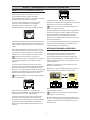 60
60
-
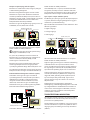 61
61
-
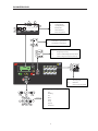 62
62
-
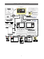 63
63
-
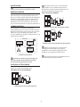 64
64
-
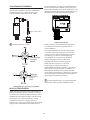 65
65
-
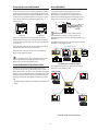 66
66
-
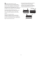 67
67
-
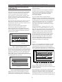 68
68
-
 69
69
-
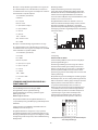 70
70
-
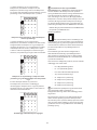 71
71
-
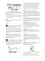 72
72
-
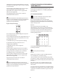 73
73
-
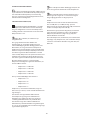 74
74
-
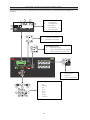 75
75
-
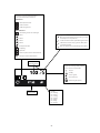 76
76
-
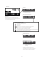 77
77
-
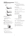 78
78
-
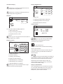 79
79
-
 80
80
-
 81
81
-
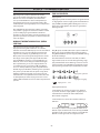 82
82
-
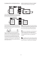 83
83
-
 84
84
-
 85
85
-
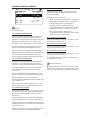 86
86
-
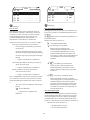 87
87
-
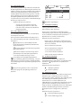 88
88
-
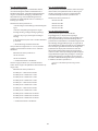 89
89
-
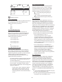 90
90
-
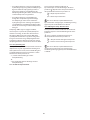 91
91
-
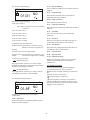 92
92
-
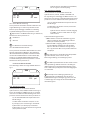 93
93
-
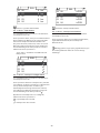 94
94
-
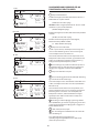 95
95
-
 96
96
-
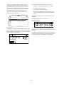 97
97
-
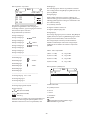 98
98
-
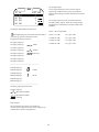 99
99
-
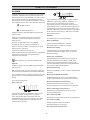 100
100
-
 101
101
-
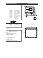 102
102
-
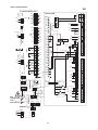 103
103
-
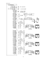 104
104
-
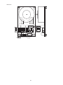 105
105
-
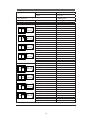 106
106
-
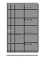 107
107
-
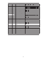 108
108
-
 109
109
-
 110
110
-
 111
111
-
 112
112
-
 113
113
-
 114
114
-
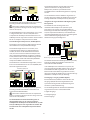 115
115
-
 116
116
-
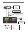 117
117
-
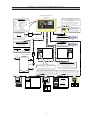 118
118
-
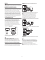 119
119
-
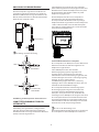 120
120
-
 121
121
-
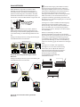 122
122
-
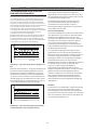 123
123
-
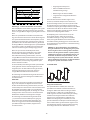 124
124
-
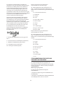 125
125
-
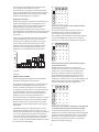 126
126
-
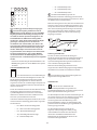 127
127
-
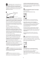 128
128
-
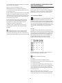 129
129
-
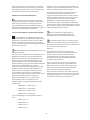 130
130
-
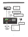 131
131
-
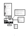 132
132
-
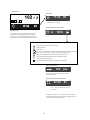 133
133
-
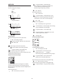 134
134
-
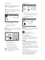 135
135
-
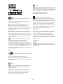 136
136
-
 137
137
-
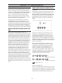 138
138
-
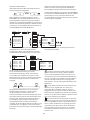 139
139
-
 140
140
-
 141
141
-
 142
142
-
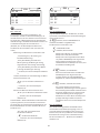 143
143
-
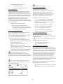 144
144
-
 145
145
-
 146
146
-
 147
147
-
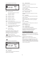 148
148
-
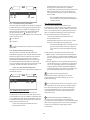 149
149
-
 150
150
-
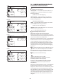 151
151
-
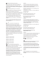 152
152
-
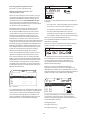 153
153
-
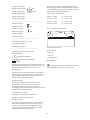 154
154
-
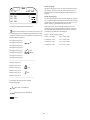 155
155
-
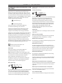 156
156
-
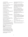 157
157
-
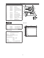 158
158
-
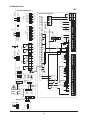 159
159
-
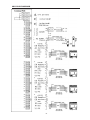 160
160
-
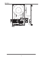 161
161
-
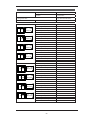 162
162
-
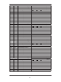 163
163
-
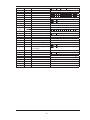 164
164
-
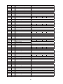 165
165
-
 166
166
-
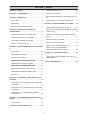 167
167
-
 168
168
-
 169
169
-
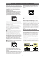 170
170
-
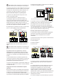 171
171
-
 172
172
-
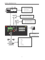 173
173
-
 174
174
-
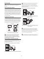 175
175
-
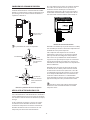 176
176
-
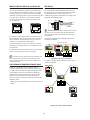 177
177
-
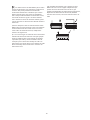 178
178
-
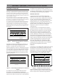 179
179
-
 180
180
-
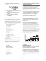 181
181
-
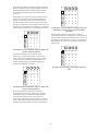 182
182
-
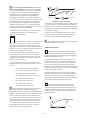 183
183
-
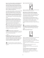 184
184
-
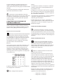 185
185
-
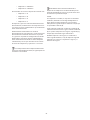 186
186
-
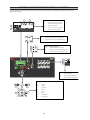 187
187
-
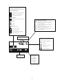 188
188
-
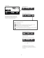 189
189
-
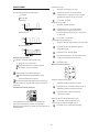 190
190
-
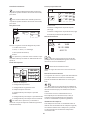 191
191
-
 192
192
-
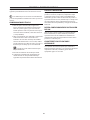 193
193
-
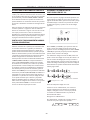 194
194
-
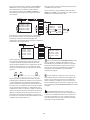 195
195
-
 196
196
-
 197
197
-
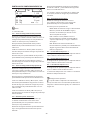 198
198
-
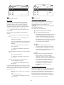 199
199
-
 200
200
-
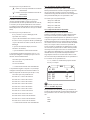 201
201
-
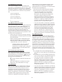 202
202
-
 203
203
-
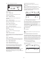 204
204
-
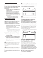 205
205
-
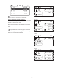 206
206
-
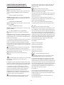 207
207
-
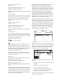 208
208
-
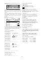 209
209
-
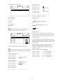 210
210
-
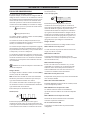 211
211
-
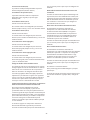 212
212
-
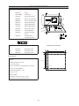 213
213
-
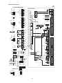 214
214
-
 215
215
-
 216
216
-
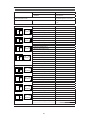 217
217
-
 218
218
-
 219
219
-
 220
220
-
 221
221
-
 222
222
-
 223
223
-
 224
224
-
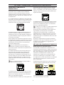 225
225
-
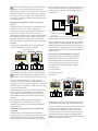 226
226
-
 227
227
-
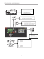 228
228
-
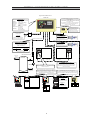 229
229
-
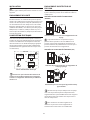 230
230
-
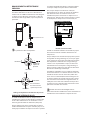 231
231
-
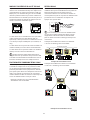 232
232
-
 233
233
-
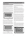 234
234
-
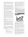 235
235
-
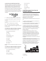 236
236
-
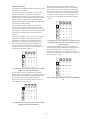 237
237
-
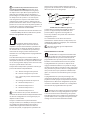 238
238
-
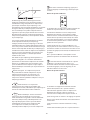 239
239
-
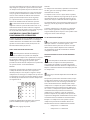 240
240
-
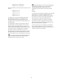 241
241
-
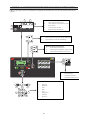 242
242
-
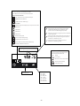 243
243
-
 244
244
-
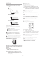 245
245
-
 246
246
-
 247
247
-
 248
248
-
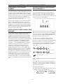 249
249
-
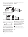 250
250
-
 251
251
-
 252
252
-
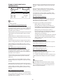 253
253
-
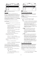 254
254
-
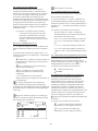 255
255
-
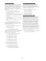 256
256
-
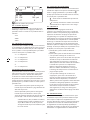 257
257
-
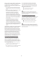 258
258
-
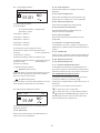 259
259
-
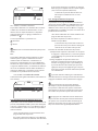 260
260
-
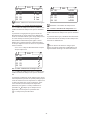 261
261
-
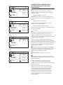 262
262
-
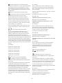 263
263
-
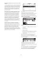 264
264
-
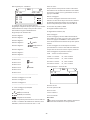 265
265
-
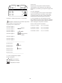 266
266
-
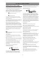 267
267
-
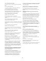 268
268
-
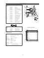 269
269
-
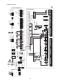 270
270
-
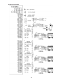 271
271
-
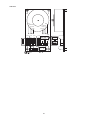 272
272
-
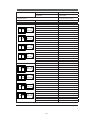 273
273
-
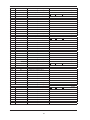 274
274
-
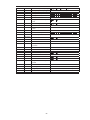 275
275
-
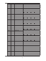 276
276
-
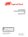 277
277
-
 278
278
-
 279
279
-
 280
280
-
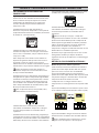 281
281
-
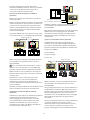 282
282
-
 283
283
-
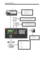 284
284
-
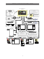 285
285
-
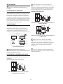 286
286
-
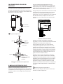 287
287
-
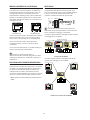 288
288
-
 289
289
-
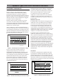 290
290
-
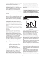 291
291
-
 292
292
-
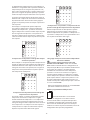 293
293
-
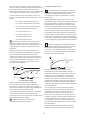 294
294
-
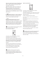 295
295
-
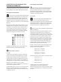 296
296
-
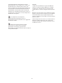 297
297
-
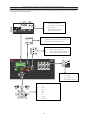 298
298
-
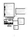 299
299
-
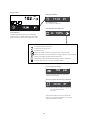 300
300
-
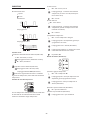 301
301
-
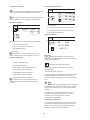 302
302
-
 303
303
-
 304
304
-
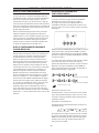 305
305
-
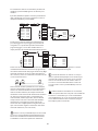 306
306
-
 307
307
-
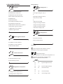 308
308
-
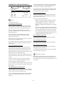 309
309
-
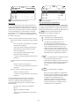 310
310
-
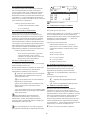 311
311
-
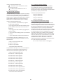 312
312
-
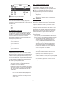 313
313
-
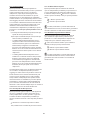 314
314
-
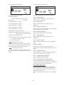 315
315
-
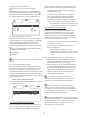 316
316
-
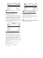 317
317
-
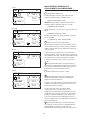 318
318
-
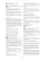 319
319
-
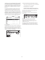 320
320
-
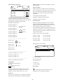 321
321
-
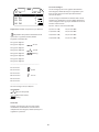 322
322
-
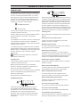 323
323
-
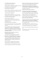 324
324
-
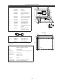 325
325
-
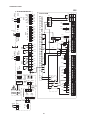 326
326
-
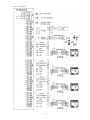 327
327
-
 328
328
-
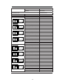 329
329
-
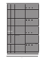 330
330
-
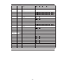 331
331
-
 332
332
-
 333
333
-
 334
334
-
 335
335
-
 336
336
-
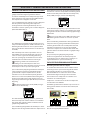 337
337
-
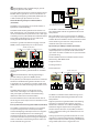 338
338
-
 339
339
-
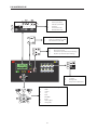 340
340
-
 341
341
-
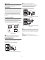 342
342
-
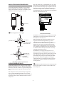 343
343
-
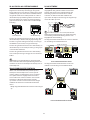 344
344
-
 345
345
-
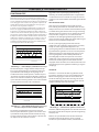 346
346
-
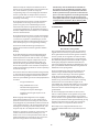 347
347
-
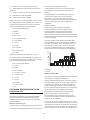 348
348
-
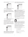 349
349
-
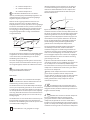 350
350
-
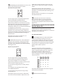 351
351
-
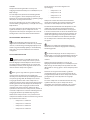 352
352
-
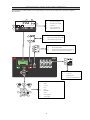 353
353
-
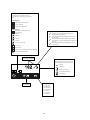 354
354
-
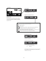 355
355
-
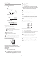 356
356
-
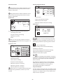 357
357
-
 358
358
-
 359
359
-
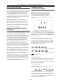 360
360
-
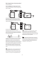 361
361
-
 362
362
-
 363
363
-
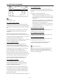 364
364
-
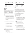 365
365
-
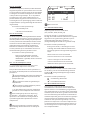 366
366
-
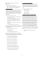 367
367
-
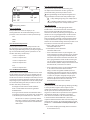 368
368
-
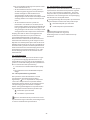 369
369
-
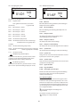 370
370
-
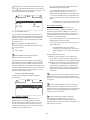 371
371
-
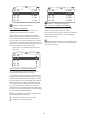 372
372
-
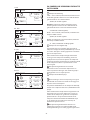 373
373
-
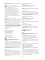 374
374
-
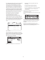 375
375
-
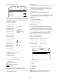 376
376
-
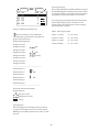 377
377
-
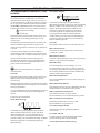 378
378
-
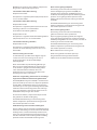 379
379
-
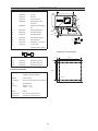 380
380
-
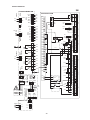 381
381
-
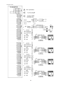 382
382
-
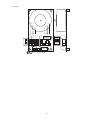 383
383
-
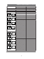 384
384
-
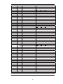 385
385
-
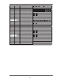 386
386
-
 387
387
-
 388
388
-
 389
389
-
 390
390
-
 391
391
-
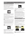 392
392
-
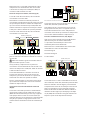 393
393
-
 394
394
-
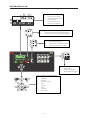 395
395
-
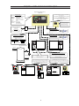 396
396
-
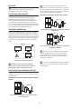 397
397
-
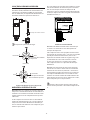 398
398
-
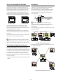 399
399
-
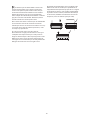 400
400
-
 401
401
-
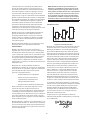 402
402
-
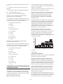 403
403
-
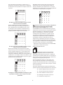 404
404
-
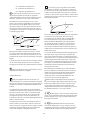 405
405
-
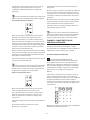 406
406
-
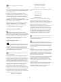 407
407
-
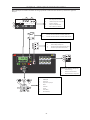 408
408
-
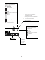 409
409
-
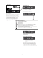 410
410
-
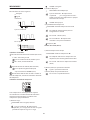 411
411
-
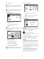 412
412
-
 413
413
-
 414
414
-
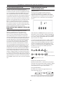 415
415
-
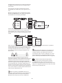 416
416
-
 417
417
-
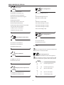 418
418
-
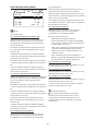 419
419
-
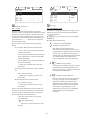 420
420
-
 421
421
-
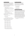 422
422
-
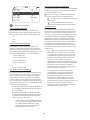 423
423
-
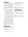 424
424
-
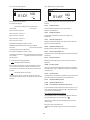 425
425
-
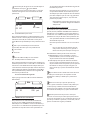 426
426
-
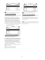 427
427
-
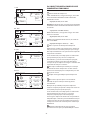 428
428
-
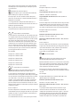 429
429
-
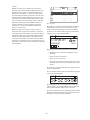 430
430
-
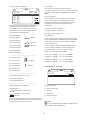 431
431
-
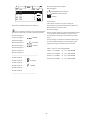 432
432
-
 433
433
-
 434
434
-
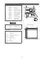 435
435
-
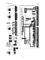 436
436
-
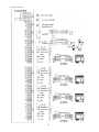 437
437
-
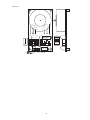 438
438
-
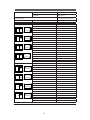 439
439
-
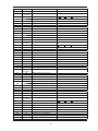 440
440
-
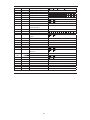 441
441
-
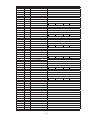 442
442
-
 443
443
-
 444
444
-
 445
445
-
 446
446
-
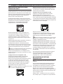 447
447
-
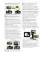 448
448
-
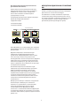 449
449
-
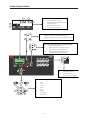 450
450
-
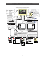 451
451
-
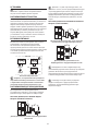 452
452
-
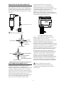 453
453
-
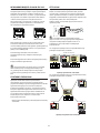 454
454
-
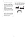 455
455
-
 456
456
-
 457
457
-
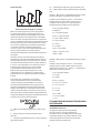 458
458
-
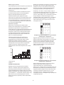 459
459
-
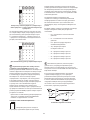 460
460
-
 461
461
-
 462
462
-
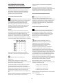 463
463
-
 464
464
-
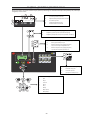 465
465
-
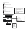 466
466
-
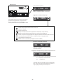 467
467
-
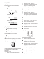 468
468
-
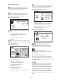 469
469
-
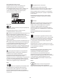 470
470
-
 471
471
-
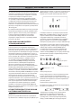 472
472
-
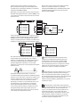 473
473
-
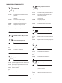 474
474
-
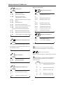 475
475
-
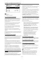 476
476
-
 477
477
-
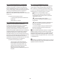 478
478
-
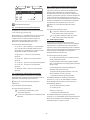 479
479
-
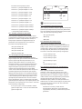 480
480
-
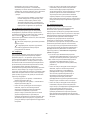 481
481
-
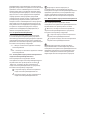 482
482
-
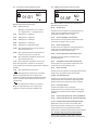 483
483
-
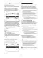 484
484
-
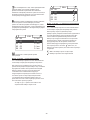 485
485
-
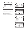 486
486
-
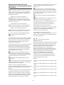 487
487
-
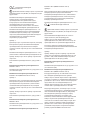 488
488
-
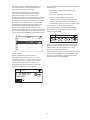 489
489
-
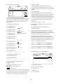 490
490
-
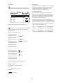 491
491
-
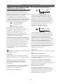 492
492
-
 493
493
-
 494
494
-
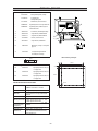 495
495
-
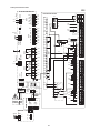 496
496
-
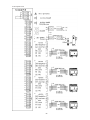 497
497
-
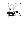 498
498
-
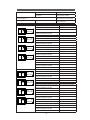 499
499
-
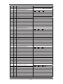 500
500
-
 501
501
-
 502
502


in altre lingue
- English: Ingersoll-Rand X8I User manual
- français: Ingersoll-Rand X8I Manuel utilisateur
- español: Ingersoll-Rand X8I Manual de usuario
- Deutsch: Ingersoll-Rand X8I Benutzerhandbuch
- русский: Ingersoll-Rand X8I Руководство пользователя
- Nederlands: Ingersoll-Rand X8I Handleiding
- português: Ingersoll-Rand X8I Manual do usuário
- dansk: Ingersoll-Rand X8I Brugermanual
Documenti correlati
Altri documenti
-
Mi Portable Electric Air Compressor (DZN4006GL) Manuale utente
-
Fly LIT MEZZANINE JULIEN ESCALIER Manuale del proprietario
-
Digicom 8E4583 IPC531-T03 Manuale utente
-
Pioneer N-30 Manuale utente
-
Novation Launchpad X Guida utente
-
CAME SRS485 Guida d'installazione
-
-
Baumer N 155 Installation and Operating Instructions
-
IMI TA TA-PILOT-R Manuale utente
-
 dirna Bergstrom SlimFIT RENAULT NET Manuale utente
