
English
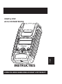
READ ENTIRE MANUAL BEFORE USING THIS PRODUCT
START & STOP
OWNER’S MANUAL
BATTERY & ELECTRICAL SYSTEM ANALYZER

English
BATTERY & ELECTRICAL SYSTEM ANALYZER
START & STOP
TEST PROCEDURES / OPERATING INSTRUCTIONS
-1 -
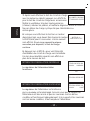
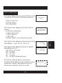
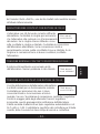
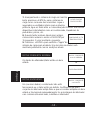
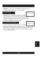
IMPORTANT烉
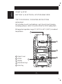
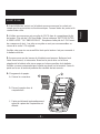
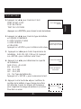
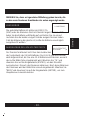
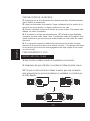
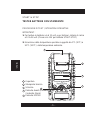
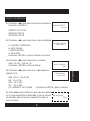
1. For testing 6 and 12 volt batteries, and 12 and 24 volt charging
& starting systems. (ONLY 12 volt for START & STOP battery test)
2. Suggested operation range 0°C (32°F) to 50°C (122°F) in ambient
temperature.
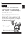
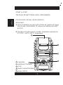
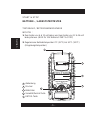
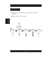
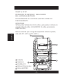
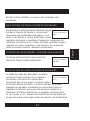
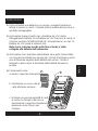
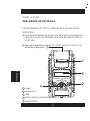
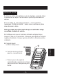
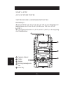
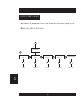
Paper Cover
Printer
Display
Directional Keys
Enter Key

English
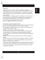
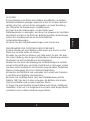
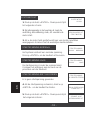
WARNING
1. Working in the vicinity of a lead acid battery is dangerous.
Batteries generate explosive gases during normal battery operation.
For this reason, it is of utmost importance, if you have any doubt,
that each time before using your tester, you read these instructions
very carefully.
2. To reduce risk of battery explosion, follow these instructions and
those published by the battery manufacturer and manufacturer of
any equipment you intend to use in the vicinity of the battery.
Observe cautionary markings on these items.
3. Do not expose the tester to rain or snow.
PERSONAL SAFETY PRECAUTIONS
1. Someone should be within range of your voice or close enough to
come to your aid when you work near a lead acid battery.
2. Have plenty of fresh water and soap nearby in case battery acid
contacts skin, clothing or eyes.
3. Wear safety glasses and protective clothing.
4. If battery acid contacts skin or clothing, wash immediately with
soap and water. If acid enters eye, immediately flood eye with
running cold water for at least ten minutes and get medical attention
immediately.
5. NEVER smoke or allow a spark or flame in vicinity of battery or
engine.
6. Be extra cautious to reduce risk of dropping a metal tool onto the
battery. It could spark or short-circuit the battery or other electrical
parts and could cause an explosion.
7. Remove personal metal items such as rings, bracelets, necklaces
and watches when working with a lead acid battery. It can produce a
short circuit current high enough to weld a ring or the like to metal
causing a severe burn.
-2 -

English
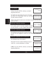
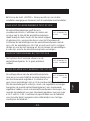
PREPARING TO TEST
1. Be sure area around battery is well ventilated while battery is
being tested.
2. Clean battery terminals. Be careful to keep corrosion from coming
in contact with eyes.
3. Inspect the battery for cracked or broken case or cover. If battery
is damaged, do not use tester.
4. If the battery is not sealed maintenance free, add distilled water in
each cell until battery acid reaches level specified by the manu
-3 -
-facturer. This helps purge excessive gas from cells. Do not overfill.
5. If necessary to remove battery from vehicle to test, always remove
ground terminal from battery first. Make sure all accessories in the
vehicle are off to ensure you do not cause any arcing.
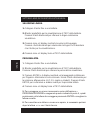
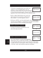
OPERATION & USE:
REPLACEM(NT OF WIRE LEAD
1. Detach the clamp lead when the replacement is necessary.
2. Make sure the new clamp lead is well connected.
NOTE that do not detach the cables unless necessary to make sure
the pins are not rusted or corroded by the acid liquid.

English
-4 -
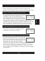
BEFORE TEST
1. Before you test a battery in a vehicle, turn off the ignition, all
accessories and loads. Close all the vehicle doors and the trunk lid.
2. Make sure you have put 4 AA 1.5V batteries into the battery
chamber. Oxyride batteries are NOT recommended because of the
initial 1.7 Volt output. If the internal 1.5V batteries run out of power,
the display will show “POWER LOW”. Replace those AA 1.5V
batteries before starting a new test.
Note that nothing will be seen on the display until the tester is
connected to a vehicle battery.
3. Make sure the battery terminals are clean. Wire brush them if
necessary. Connect the red clamp to the positive battery terminal
post; connect the black clamp to the negative battery terminal post.
For the most accurate results, clamp on the lead part of the terminal
only. Attaching to the clamp or fixture rather than directly on the
terminal will lead to unstable wrong test results.
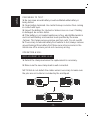
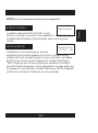
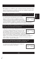
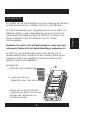
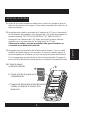
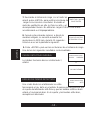
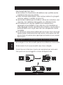
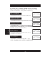
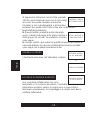
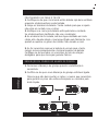
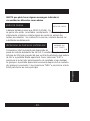
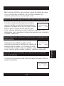
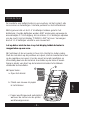
4. Paper load:
a. Open the clear cover.
b. Place a new paper roll
in the compartment.
c. Paper will be fed automatically
when the sensor of printer is sensed.
b
a

English
-5 -
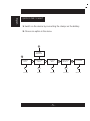
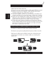
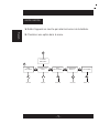
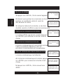
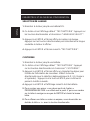
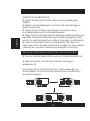
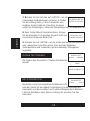
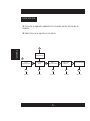
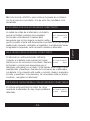
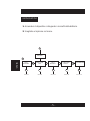
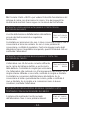
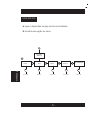
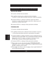
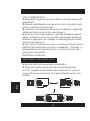
QUICK START CHART
1. Switch on the device by connecting the clamps on the battery.
2. Choose an option in the menu.
START-STOP
TEST
See P.8 See P.6 See P.11 See P.15 See P. 15
BATTERY
TEST
SYSTEM
ANALYSER
SYSTEM
TEST
LANGUAGE
SELECT
1
2
CUSTOMIZE

English
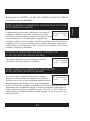
-6 -
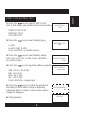
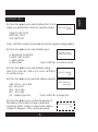
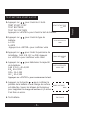
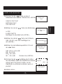
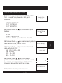
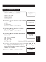
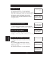
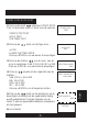
START-STOP BATTERY TEST
1. Press the
key to select START-STOP
Test. In this stage, you will find 3 tests for selection.
START-STOP TEST
BATTERY TEST
SYSTEM TEST
2. Press the
key to select battery type
a. EFB
b. AGM FLAT PLATE
Press «ENTER» to confirm choice.
3. Press the
key to select battery rating:
SAE (CCA), EN, IEC or DIN. Press «ENTER»
to confirm choice.
4. Press the
key to input the battery capacity:
SAE (CCA)
40~2,000
EN
40~2,100
DIN
25~1,300
IEC
30~1,500
Press «ENTER» to begin test.
5. Press the
key to confirm the position of
the battery if the surface charge is detected.
Follow the tester ‘s steps to remove the surface
charge if it happens.
6. Testing battery.
BATTERY TYPE
EFB
START-STOP
TEST
SELECT RATING
SAE
SET CAPACITY
XXXX SAE
TEST IN VEHICLE?
NO
TESTING

English
-7 -
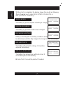
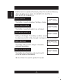
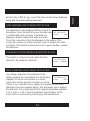
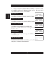
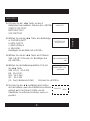
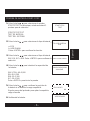
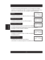
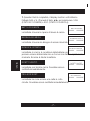
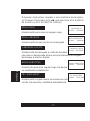
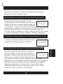
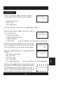
7. When test is completed, the display shows the results as following
{Press theŻ Ź key to select: SOH (STATE OF HEALTH) or
SOC (STATE OF CHARGE)}.
GOOD & PASS
The battery is good & capable of holding a charge.
GOOD & RECHARGE
The battery is good but needs to be recharged.
RECHARGE & RETEST
Battery is discharged. The battery condition cannot
be determined until it is fully charged. Recharge & retest the battery.
BAD & REPLACE
The battery will not hold a charge. It should be
replaced immediately.
BAD CELL & REPLACE
The battery has at least one cell short circuit. It
should be replaced immediately.
8. End of test. Proceed the printout if needed.
GOOD & PASS
XX.XXV XXXXSAE
BAD & REPLACE
XX.XXV XXXXSAE
RECHARGE & RETEST
XX.XXV XXXXSAE
GOOD & RECHARGE
XX.XXV XXXXSAE
BAD CELL & REPLACE
XX.XXV XXXXSAE

English
-8 -
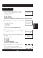
1. Press the Ż Ź key to select Battery Test. In this
stage, you will find the 3 tests for selection below.
START-STOP TEST
BATTERY TEST
SYSTEM TEST
Press «ENTER» button to proceed the test for regular starting battery.
2. Press the Ż Ź key to select battery type
a. REGULAR FLOODED
b. AGM FLAT PLATE
c. AGM SPIRAL
d. VRLA/GEL Press «ENTER» to confirm choice.
3. Press the Ż Ź key to select battery rating:
SAE (CCA), EN, IEC, DIN or JIS. Press «ENTER»
to confirm choice.
4. Press the Ż Ź key to input the battery capacity:
SAE (CCA) 40~2,000
EN 40~2,100
DIN 25~1,300
IEC 30~1,500
JIS Battery Type No. Press «ENTER» to begin test.
5. Press the Ż Ź key to confirm the position of
the battery if the surface charge is detected.
Follow the tester ‘s steps to remove the surface
charge if it happens. Then testing proceeds.
BATTERY TYPE
AGM FLAT PLATE
BATTERY TEST
XX.XXV
SELECT RATING
SAE
SET CAPACITY
XXXX SAE
TEST IN VEHICLE?
NO
BATTERY TEST

English
-9 -
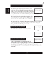
6. When test is completed, the display shows the results as following
{Press theŻ Ź key to select: SOH (STATE OF HEALTH) or
SOC (STATE OF CHARGE)}.
GOOD & PASS
The battery is good & capable of holding a charge.
GOOD & RECHARGE
The battery is good but needs to be recharged.
RECHARGE & RETEST
Battery is discharged. The battery condition cannot
be determined until it is fully charged. Recharge & retest the battery.
BAD & REPLACE
The battery will not hold a charge. It should be
replaced immediately.
BAD CELL & REPLACE
The battery has at least one cell short circuit. It
should be replaced immediately.
12. End of test. Proceed the printout if needed.
GOOD & PASS
XX.XXV XXXXSAE
BAD & REPLACE
XX.XXV XXXXSAE
RECHARGE & RETEST
XX.XXV XXXXSAE
GOOD & RECHARGE
XX.XXV XXXXSAE
BAD CELL & REPLACE
XX.XXV XXXXSAE

English
- 10 -
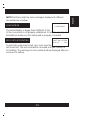
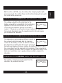
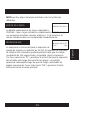
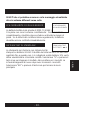
NOTE that there might be some messages displayed to different
circumstances as below.
LOAD ERROR
The tested battery is bigger than 2000SAE (CCA).
Or the connection is not properly established. Check the capacity of
the battery & make sure the clamp lead is properly connected.
24V SYSTEM PRINTING
To print 24V system test result, user must save the
test result first. The test result will be recorded until you connect to
12V battery. The message to check printout will be displayed after you
reconnect to battery.
LOAD ERROR
PRINT 24V SYSTEM
RESULT? YES

English
-11 -
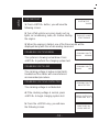
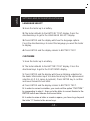
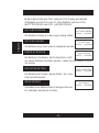
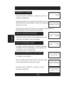
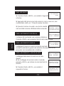
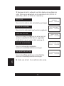
SYSTEM TEST
1. Press «ENTER» button, you will view the
following screen.
2. Turn off all vehicle accessory loads such as
lights, air conditioning, radio, etc. Before starting
the engine.
3. When the engine is started, one of the three results will be
displayed along with the actual reading measured.
CRANKING VOLTS NORMAL
The system is showing normal draw. Press
«ENTER» to perform the charging system test.
CRANKING VOLTS LOW
The cranking voltage is below normal limits,
troubleshoot the starter with manufacturers
recommended procedure.
CRANKING VOLTS NO DETECTED
The cranking voltage is not detected.
4. If the cranking voltage is normal, press
«ENTER» to begin charging system test.
5. Press the «ENTER» key, you will view
the following screen.
SYSTEM TEST
XX.XXV
TURN OFF LOADS
START ENGINE
CRANKING VOLTS
XX.XXV NORMAL
CRANKING VOLTS
XX.XXV LOW
CRANKING VOLTS
NO DETECTED
PRESS ENTER FOR
= CHARGING TEST =
MAKE SURE ALL
LOADS ARE OFF

English
- 12 -
6. Press the «ENTER» key, one of the three results will be displayed
along with the actual reading measured.
LOW CHARGING VOLTS WHEN TEST AT IDLE
The alternator is not providing sufficient current to
the battery. Check the belts to ensure the alternator
is rotating with engine running. If the belts are
slipping or broken, replace the belts and retest.
Check the connections from the alternator to the battery. If the
connection is loose or heavily corroded, clean or replace the cable
and retest. If the belts and connections are in good condition, replace
the alternator.
CHARGING SYSTEM NORMAL WHEN TEST AT IDLE
The system is showing normal output from the
alternator. No problem is detected.
HIGH CHARGING VOLTS WHEN TEST AT IDLE
The voltage output from the alternator to the
battery exceeds the normal limits of a functioning
regulator. Check to ensure there is no loose
connection and the ground connection is normal.
If there is no connection issue, replace the regulator. Since most
alternators have the regulator built-in, this will require you to replace
the alternator. The normal high limit of a typical automotive regulator
is 14.7 volts +/- 0.05. Check manufacturer specifications for the
correct limit, as it will vary by vehicle type and manufacturer.
ALT. IDLE VOLTS
XX.XXV LOW
ALT. IDLE VOLTS
XX.XXV NORMAL
ALT. IDLE VOLTS
XX.XXV HIGH

English
-13 -
7. Following the charging system at idle, press
«ENTER» for the charging system with accessory
loads. Turn on the blower to high (heat), high beam
headlights, and rear defogger (If equipped). Do not
use cyclical loads such as air conditioning or windshield wipers.
8. When testing older model diesel engines, the
users need to run up the engine to 2500 rpm for
15 seconds. You will view the screen as follows:
9. Press «ENTER» to look for the amount of ripple from the charging
system to the battery. One of two testing results will be displayed
along with the actual testing measured.
RIPPLE DETECTED NORMAL
Diodes function well in the alternator / stator.
EXCESS RIPPLE DETECTED
One or more diodes in the alternator are not
functioning or there is stator damage. Check to ensure the alternator
mounting is sturdy and that the belts are in good shape and
functioning properly. If the mounting and belts are good, replace the
alternator.
TURN ON LOADS
AND PRESS ENTER
RUN ENGINE UP TO
2500 RPM 15 SEC.
OR
RIPPLE DETECTED
XX.XXV NORMAL
NO RIPPLE DETECT
RIPPLE DETECTED
XX.XXV HIGH

English
- 14 -
10. Press the «ENTER» key to continue the charging system with
accessory loads. One of the three results will be displayed along with
the actual testing measured.
CHARGING SYSTEM HIGH WHEN TEST WITH ACC. LOADS
The voltage output from the alternator to the
battery exceeds the normal limits of a functioning
regulator. Check to ensure there are no loose
connections and that the ground connection is
normal. If there are no connection issues, replace the regulator.
Since most alternators have the regulator built-in, this will require
you to replace the alternator.
CHARGING SYSTEM LOW WHEN TEST WITH ACC. LOADS
The alternator is not providing sufficient current for
the system’s electrical loads and the charging
current for the battery. Check the belts to ensure
the alternator is rotating with the engine running. If
the belts are slipping or broken, replace the belts and retest. Check
the connections from the alternator to the battery. If the connection is
loose or heavily corroded, clean or replace the cable and retest. If the
belts and connections are in good working condition, replace the
alternator.
CHARGING SYSTEM NORMAL WHEN TEST WITH ACC. LOADS
The system is showing normal output from the
alternator. No problem detected.
ALT. LOAD VOLTS
XX.XXV HIGH
ALT. LOAD VOLTS
XX.XXV LOW
ALT. LOAD VOLTS
XX.XXV NORMAL

English
-15 -
SETTINGS AND INFORMATION RETRIEVAL
LANGUAGE SELECT
1. Hook the tester up to a battery.
2. The tester defaults to the BATTERY TEST display. Press the
directional keys to get to the LANGUAGE SELECT display.
3. Press ENTER and the display will show the language options.
Press the directional keys to select the language you want the tester
to display.
4. Press ENTER and the display returns to BATTERY TEST.
CUSTOMIZE
Hook the tester up to a battery.
The tester defaults to the BATTERY TEST display. Press the
directional keys to get to the CUSTOMIZE display.
Press ENTER and the display will show an blinking underline for
the dealer information input. Use directional key for the alphanumeric
selection (A-Z, 0-9, space & symbols). Press ENTER key to confirm
and move forward to next letter.
Press ENTER and the display returns to BATTERY TEST.
,QRUGHUWRFRUUHFWDPLVWDNH\RXPXVWH[LWWKHRSWLRQ&86720
E\SURFHHGLQJWRVWHSWKHQJRWRWKHOHWWHUWRFRUUHFWWKDQNVWRWKH
(17(5EXWWRQDQGFKRRVHWKHFRUUHFWOHWWHU
,QRUGHUWRHUDVHDOHWWHURUFUHDWHDVSDFH\RXKDYHWRJREH\RQG
WKHOHWWHU]WKDQNVWRWKHDUURZNH\V

French
LIRE L'INTÉGRALITÉ DU MANUEL AVANT D'UTILISER CE PRODUIT.
START & STOP
MANUEL D’UTILISATION
TESTEUR DE BATTERIES AVEC IMPRIMANTE

French
TESTEUR DE BATTERIES AVEC IMPRIMANTE
START & STOP
PROCÉDURES D'ESSAI / MODE D'EMPLOI
-1 -
IMPORTANT烉
1. Testez les batteries de 6 &12 volts et testez du système de charge
12 & 24 volts. (SEULEMENT 12 volt pour les batteries de START
& STOP)
2. Intervalle de fonctionnement conseillé : température ambiante de
0°C (32°F) à 50°C (122°F) temperature.
Couverture
Imprimante Thermique
Écran
Bouton Suivant/Précédent
Bouton ENTER

French
AVERTISSEMENT
1. ll est dangereux de travailler près d'une batterie au plomb-acide.
Lors du fonctionnement normal d'une batterie, des gaz explosifs sont
émis. Pour cette raison il est primordial de lire et de suivre les
instructions, chaque fois que vous utilisez votre testeur.
2. Afin de réduire les risques d'explosion de la batterie, vous devez
suivre ces instructions ainsi que celles du fabricant de la batterie ou
du fabricant de tout équipement utilisé près de la batterie.
Lisez les avertissements apposés sur ces produits.
3. Ne pas exposer le testeur à la pluie ou a la neige.
PPRÉCAUTIONS DE SÉCURITÉ
1. Assurez-vous qu'il y a quelqu'un à porteé du vue ou suffisamment
près pour venir à votre aide lorsque vous travaillez près d'une
batterie au plomb-acide.
2. Assurez-vous d'avoir une bonne quantité d'eau fraîche et du savon
à proximité, au cas ou votre peau, vos yeux ou vos vêtements
entreraient en contact avec l'acide de la batterie.
3. Portez des verres de sécurité et des vêtements appropriés.
Évitez de toucher à vos yeux lorsque vous travaillez près d'une
batterie.
4. Si l'acide de la batterie entre en contact avec votre peau ou vos
vêtements, lavez-les immédiatement avec de l'eau et du savon.
Si l'acide pénètre dans vos yeux, aspergez-les d'eau courante froide
pour au moins 10 minutes et consultez un médecin immédiatement.
5. Ne jamais fumer ou permettre des étincelles ou des flammes près
de la batterie ou du moteur.
6. Soyez très vigilent afin de réduire les risques d'échapper un outil
en métal sur la batterie. Une étincelle, un court-circuit à la batterie
ou à une autre composante électrique peuvent causer une explosion.
7. Enlevez bagues, chaînes, bracelets, montres ou tout autre objet
métallique lorsque vous travaillez avec une batterie au plomb-acide.
Une batterie au plomb-acide peut causer un court-circuit assez
puissant pour faire fondre une bague ou autre, et causer des brûlures
sévères.
-2 -

French
AVANT D'EFFECTUER UN TEST
1. Assurez-vous que l'endroit est bien ventilé avant d'effectuer un test.
2. Nettoyez les bornes de la batterie. Faites attention pour que la
corrosion n'entre pas en contact avec vos yeux.
3. Inspecter la batterie, vérifiez s'il y a des fissures, si le boîtier ou le
couvercle est brisé. S'il y a des dommages, n'utilisez pas le testeur.
4. Ajoutez de l'eau distillée dans chaque cellule jusqu'à ce que l'acide
atteigne le niveau spécifié par le fabriquant de batterie Ceci aide à
purger l'excès de gaz dans les cellules. Ne pas trop remplir.
5. S'il est nécessaire d'enlever la batterie du véhicule pour effectuer
le test, enlevez toujours la borne de terre en premier. Assurez-vous
que tous les accessoires sur le véhicule ne sont pas en fonction
afin d'éviter un jaillissement de l'acide.
-3 -
INSTALLATION OU 5(03/$&(0(17 DES SERRE-CABLE
1. Retirez le couvercle à l’arrière sous le testeur de la pile.
2. Assurez-vous que la nouvelle piste de la pince est bien connecté.
Notez que ne retirez pas les câbles à moins de si nécessaire pour
s'assurer que les broches ne sont pas rouillés ou corrodés par le
liquide acid.
La pagina si sta caricando...
La pagina si sta caricando...
La pagina si sta caricando...
La pagina si sta caricando...
La pagina si sta caricando...
La pagina si sta caricando...
La pagina si sta caricando...
La pagina si sta caricando...
La pagina si sta caricando...
La pagina si sta caricando...
La pagina si sta caricando...
La pagina si sta caricando...
La pagina si sta caricando...
La pagina si sta caricando...
La pagina si sta caricando...
La pagina si sta caricando...
La pagina si sta caricando...
La pagina si sta caricando...
La pagina si sta caricando...
La pagina si sta caricando...
La pagina si sta caricando...
La pagina si sta caricando...
La pagina si sta caricando...
La pagina si sta caricando...
La pagina si sta caricando...
La pagina si sta caricando...
La pagina si sta caricando...
La pagina si sta caricando...
La pagina si sta caricando...
La pagina si sta caricando...
La pagina si sta caricando...
La pagina si sta caricando...
La pagina si sta caricando...
La pagina si sta caricando...
La pagina si sta caricando...
La pagina si sta caricando...
La pagina si sta caricando...
La pagina si sta caricando...
La pagina si sta caricando...
La pagina si sta caricando...
La pagina si sta caricando...
La pagina si sta caricando...
La pagina si sta caricando...
La pagina si sta caricando...
La pagina si sta caricando...
La pagina si sta caricando...
La pagina si sta caricando...
La pagina si sta caricando...
La pagina si sta caricando...
La pagina si sta caricando...
La pagina si sta caricando...
La pagina si sta caricando...
La pagina si sta caricando...
La pagina si sta caricando...
La pagina si sta caricando...
La pagina si sta caricando...
La pagina si sta caricando...
La pagina si sta caricando...
La pagina si sta caricando...
La pagina si sta caricando...
La pagina si sta caricando...
La pagina si sta caricando...
La pagina si sta caricando...
La pagina si sta caricando...
La pagina si sta caricando...
La pagina si sta caricando...
La pagina si sta caricando...
La pagina si sta caricando...
La pagina si sta caricando...
La pagina si sta caricando...
La pagina si sta caricando...
La pagina si sta caricando...
La pagina si sta caricando...
La pagina si sta caricando...
La pagina si sta caricando...
La pagina si sta caricando...
La pagina si sta caricando...
La pagina si sta caricando...
La pagina si sta caricando...
La pagina si sta caricando...
La pagina si sta caricando...
La pagina si sta caricando...
La pagina si sta caricando...
La pagina si sta caricando...
La pagina si sta caricando...
La pagina si sta caricando...
La pagina si sta caricando...
La pagina si sta caricando...
La pagina si sta caricando...
La pagina si sta caricando...
La pagina si sta caricando...
La pagina si sta caricando...
-
 1
1
-
 2
2
-
 3
3
-
 4
4
-
 5
5
-
 6
6
-
 7
7
-
 8
8
-
 9
9
-
 10
10
-
 11
11
-
 12
12
-
 13
13
-
 14
14
-
 15
15
-
 16
16
-
 17
17
-
 18
18
-
 19
19
-
 20
20
-
 21
21
-
 22
22
-
 23
23
-
 24
24
-
 25
25
-
 26
26
-
 27
27
-
 28
28
-
 29
29
-
 30
30
-
 31
31
-
 32
32
-
 33
33
-
 34
34
-
 35
35
-
 36
36
-
 37
37
-
 38
38
-
 39
39
-
 40
40
-
 41
41
-
 42
42
-
 43
43
-
 44
44
-
 45
45
-
 46
46
-
 47
47
-
 48
48
-
 49
49
-
 50
50
-
 51
51
-
 52
52
-
 53
53
-
 54
54
-
 55
55
-
 56
56
-
 57
57
-
 58
58
-
 59
59
-
 60
60
-
 61
61
-
 62
62
-
 63
63
-
 64
64
-
 65
65
-
 66
66
-
 67
67
-
 68
68
-
 69
69
-
 70
70
-
 71
71
-
 72
72
-
 73
73
-
 74
74
-
 75
75
-
 76
76
-
 77
77
-
 78
78
-
 79
79
-
 80
80
-
 81
81
-
 82
82
-
 83
83
-
 84
84
-
 85
85
-
 86
86
-
 87
87
-
 88
88
-
 89
89
-
 90
90
-
 91
91
-
 92
92
-
 93
93
-
 94
94
-
 95
95
-
 96
96
-
 97
97
-
 98
98
-
 99
99
-
 100
100
-
 101
101
-
 102
102
-
 103
103
-
 104
104
-
 105
105
-
 106
106
-
 107
107
-
 108
108
-
 109
109
-
 110
110
-
 111
111
-
 112
112


in altre lingue
- English: USAG 890K User manual
- français: USAG 890K Manuel utilisateur
- español: USAG 890K Manual de usuario
- Deutsch: USAG 890K Benutzerhandbuch
- Nederlands: USAG 890K Handleiding
- português: USAG 890K Manual do usuário
Altri documenti
-
Bahco BBT60 Manuale utente
-
Facom BAT.TEST Manuale utente
-
 JBM 52233 Guida utente
-
GYS BATTERY TESTER DBT350 Scheda dati
-
GYS BATTERY TESTER DBT400 Scheda dati
-
-
-
DHC BT2010 Manuale del proprietario
-
GYS BATTERY TESTER PBT824 - 12/24V Scheda dati
-
 Topdon BTMOBILE PRO Manuale utente

