
Valvole Bitubo
Robinets Bitube monopoint
Zweirohrthermostatventile
Two-pipe system valves
Válvulas Bitubo
Válvulas Bitubo
Tweepijpsaansluitcombinaties
Клапаны для двухтрубной системы
Temperatura massima di esercizio: 5÷110 °C (5÷90 °C con sonda in plastica)
Température maximale de service: 5÷110 °C (5÷90 °C avec sonde en plastique)
Max. Betriebstemperatur: 5÷110 °C (5÷90 °C mit Kunststo-Sonde)
Max. working temperature: 5÷110 °C (5÷90 °C with plastic sensor)
Temperatura máxima de ejercicio: 5÷110 °C (5÷90 °C con sonda de plástico)
Temperatura máxima de exercício: 5÷110 °C (5÷90 °C com sonda de plástico)
Max. watertemperatuur: 5÷110 °C (5÷90 °C met kunststof probe)
Максимальная рабочая температура: 5÷110 °C (5÷90 °C с пластиковым зондом)
Pressione massima di esercizio: 10 bar
Pression maximale de service: 10 bar
Max. Betriebsdruck: 10 bar
Max. working pressure: 10 bar
Presión máxima de ejercicio: 10 bar
Pressão máxima de exercício: 10 bar
Max. werkdruk: 10 bar
Максимальное рабочее давление: 10 bar
Pressione dierenziale massima (con testa termostatica): 1,4 bar
Pression diérentielle maximale (avec tête thermostatique): 1,4 bar
Max. Dierenzdruck (mit Thermostat): 1,4 bar
Max dierential pressure (with thermostatic head): 1,4 bar
Presión diferencial máxima (con la cabeza termostática): 1,4 bar
Pressão diferencial máxima (com cabeça termostática): 1,4 bar
Max. dierentieeldruk (Met thermostaat): 1,4 bar
Максимальный перепад давления (με θερμοστάτη): 1,4 bar
Valvole Monotubo
Robinets Monotube monopoint
Einrohrthermostatventile
Single pipe system valves
Válvulas Monotubo
Válvulas Monotubo
Eénpijpsaansluitcombinaties
Клапаны для однотрубной системы
Temperatura massima di esercizio: 5÷110 °C (5÷90 °C con sonda in plastica)
Température maximale de service: 5÷110 °C (5÷90 °C avec sonde en plastique)
Max. Betriebstemperatur: 5÷110 °C (5÷90 °C mit Kunststo-Sonde)
Max. working temperature: 5÷110 °C (5÷90 °C with plastic sensor)
Temperatura máxima de ejercicio: 5÷110 °C (5÷90 °C con sonda de plástico)
Temperatura máxima de exercício: 5÷110 °C (5÷90 °C com sonda de plástico)
Max. watertemperatuur: 5÷110 °C (5÷90 °C met kunststof probe)
Максимальная рабочая температура: 5÷110 °C (5÷90 °C с пластиковым зондом)
Pressione massima di esercizio: 10 bar
Pression maximale de service: 10 bar
Max. Betriebsdruck: 10 bar
Max. working pressure: 10 bar
Presión máxima de ejercicio: 10 bar
Pressão máxima de exercício: 10 bar
Max. werkdruk: 10 bar
Максимальное рабочее давление: 10 bar
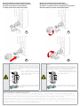
Il bocchettone “autotenuta” Giacomini è dotato di un elemento in materiale elastomerico che lo predispone al montaggio sul corpo scaldante
senza aggiunta di canapa, pasta o altri materiali di tenuta. Per il serraggio del bocchettone è suciente applicare una coppia non superiore a 25
Nm, lubricando eventualmente l’elemento in materiale elastomerico con prodotti a base siliconica.
La douille “autoétanche” Giacomini est livré avec un élément en matériel élastomère qui per-met de la monter sur le radiateur sans ajout de llasse,
de patte ou d’autre produit d’étanchéité. Pour le serrage de la douille il est susant d’appliquer un couple pas plus haut que 25 Nm, en lubriant
au besoin l’élément en matériel élastomère avec des produits à base de silicone.
Die „selbstdichtende“ Tülle von Giacomini mit einem Dichtring aus elastomeren Material, er-möglicht ein Abdichten in den Heizkörper ohne Hanf,
Kleber oder andere Dichtungsmaterialien ver-wenden zu müssen. Beim Reindrehen der Tülle ist darauf zu achten dass der Drehmoment nicht
grö-ßer als 25 Nm beträgt. Vorher ist das Dichtelement mit etwas Öl auf Silikonbasis einzuschmieren.
Giacomini self-sealing tail piece is provided with an element made of elastomeric material that arranges it for mounting on the radiator without
adding hemp, glue or other sealing materials. In order to tighten the tail piece it is sucient to apply a torque not higher than 25 Nm, by lubricating
the ele-ment in elastomeric material, if necessary, with silicone base products.
El enlace con “autojunta” Giacomini esta provisto de un elemento de cierre en material elastó-mero que permite el montaje de la válvula al radiador sin tener la necesidad de
añadir cáñamo u otros materiales. Dado el tipo de cierre, es suciente con aplicar un par de apriete no superior a 25Nm. Pa-ra un correcto montaje se recomienda lubricar
ligeramente la rosca antes de empezar el roscado.
O Ligador “auto-vedante” Giacomini é fornecido com uma junta de material elastomérico que o torna apto para a montagem sobre radiadores sem recorrer a linho ou outros
materiais de vedação. Para apertar o ligador é suciente aplicar uma força não superior a 25 Nm, lubricando o elemento em material elastomérico com produtos de base silicónica.
Het zelfdichtend puntstuk Giacomini is uitgerust met een elastomeer afdichtingsmateriaal zodat het puntstuk direct in het verwarmingslichaam ge-schroefd kan worden,
zonder gebruik van bijkomende bevesti-gingsmaterialen. Voor het aandraaien volstaat een mo-ment van maximum 25 Nm, eventueel gebruik makend van een smeermiddel
op basis van siliconen.
Патрубок “autotenuta” Giacomini снабжен эластичным елементом, который позволяет монтировать его на радиаторы без дополнительных герметичных елементов
(конопля, паста и др.). Для правильного монтажа патрубка достаточно произвести закручивание не более 25 Nm предварительно смазав еластичный елемент.
047U31818 Marzo 2017 - March 2017
ValVole monotubo e bitubo
Single-pipe and twin-pipe ValVeS

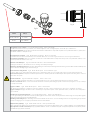
Code Set (s)
R171C / R171P 2÷3 mm
R171F 1,4÷2,0 mm
s
Fig. A
Fig. B
Collegamento al corpo scaldante: Fig. B R171C / R171P = plastica R171F = rame lettato
Per ottenere una buona resa del corpo scaldante, si raccomanda di applicare sonde con lunghezza pari a circa 2/3 del corpo scaldante stesso.
Collegamento all’impianto: Nel collegamento della valvola alle tubazioni di alimentazione è importante rispettare il senso preferenziale del usso, quando questo
viene indicato dalle frecce stampate sul corpo.
Raccordement sur le radiateur: Fig. B R171C / R171P = en plastique R171F = en cuivre leté
Pour obtenir une bonne émission du radiateur, il est recommandé d’utiliser une son de d’une longueur d’environ les 2/3 de le longueur du radiateur.
Raccordement à l’installation: Pour le raccordement du robinet sur les tubes d’alimentation il est important de respecter le sens pré-férentiel du uide, ce sens
est donné par les èches matricées sur le corps.
Anschluss an den Heizkörper: Fig. B R171C / R171P = Kunststo R171F = Gewinde Kupfer
Die Länge des Tauchrohres sollte mindestens 2/3 von der Länge des Heizkörpers betragen.
Anschluss an das Heizungssystem: Beim Anschluss der Rohrleitungen an das Ventil, ist unbedingt auf die Flussrichtung zu achten. Pfeile auf dem Ventilkörper und
in den technischen Unterlagen zeigen die Flussrichtung an.
Connection to the eating element: Fig. B R171C / R171P = plastic R171F = threaded copper
In order to obtain a good output of the heating element, it is recommended to apply sensors of a length equal to approx 2/3 of the eating element itself.
Connection to the system: It is important to follow the preferential sense of the ow, when this is indicated by the arrows printed on the body, for the connection
of the valve to the system.
Conexión al radiador: Fig. B R171C / R171P = de plástico R171F = cobre roscado
Para obtener un buen rendimiento del radiador, se recomienda instalar una sonda con una longitud aproximada de 2/3 de la del propio radiador.
Conexión a la instalación: Para la conexión de la válvula a las tuberías de entrada y salida del agua, respetar el sentido de ujo del agua en caso que se indique
en el cuerpo de la válvula.
Ligação ao radiador: Fig. B R171C / R171P = plástico R171F = cobre threaded
Para obter um bom rendimento do radiador recomenda-se a utilização de sondas com um com-primento que seja de 2/3 do comprimento do radiador.
Ligação à instalação: Na ligação da válvula aos tubos de alimentação é importante respeitar o sentido preferencial do uxo, a vericar nas setas estampadas no
corpo da válvula.
Aansluiting aan het verwarmingslichaam: Fig. B R171C / R171P = plastic R171F = schroefdraad koper
Voor een goede werking dient het uiteinde van de inspuitbuis gelijk te komen met het uiteinde van het puntstuk en dient de lengte van de inspuitbuis gelijk te
zijn aan 2/3 van de lengte van het verwar-mingslichaam.
Aansluiting aan de leidingen: Bij de aansluiting van de aansluitcombinatie aan de aanvoer- en de retourleidingen dient de stro-mingsrichting gerespecteerd te
worden, zoals aangegeven door de pijlen op het lichaam van de aans-luitcombinatie.
Подключение к радиатору: Fig. B R171C / R171P = пластик R171F = резьбовые меди
Для достижения необходимой теплоотдачи радиатора рекомендуется использовать зонды, длина которых составляет примерно 2/3 от длины радиатора.
Подсоединение к системе отопления: Для подсоединения клапана к системе отопления необходимо соблюдать направление потока, как это указано
стрелками непосредственно на клапане.

La protezione da cantiere o il volantino manuale consentono di parzializzare la portata della valvola. Ruotando in senso antiorario si apre la valvola mentre con rotazione oraria
si ottiene la sua chiusura.
Per le valvole con volantino manuale, in caso di funzionamento in “manuale” la regolazione micrometrica può essere eettuata togliendo la parte superiore della manopola e
del piolino che andrà poi rimontato nella posizione corrispondente al numero rilevato sullo specico diagramma di taratura.
Le capuchon de chantier ou le volant manuel permettent de régler le débit dans le robinet : en tournant la partie rouge ou le volant dans le sens des contraire des aiguille d’une
montre on ouvre le robinet, alors que dans le sans des aiguilles d’une montre on ferme le robinet.
En cas de fonctionnement « manuel » le réglage du débit pet être fait en enlevant délicatement la par-tie supérieure de la tête manuel et en positionnant le clou de réglage
sur la position déterminer a partir du diagramme d’équilibrage.
Mit Hilfe des Handrads oder der Schutzkappe lässt sich das Ventil schrittweise önen. Durch Drehen entgegen dem Uhrzeigersinn önet sich das Ventil, durch Drehen im
Uhrzeigersinn schließt es.
Bei „Hand-„ Betrieb lasst sich die Einstellung durch Entfernen des Stiftes aus dem Oberteil errechen. Bei Wiedereinbau ist die Position zu wählen, die dem Wert im entsprechen-
den Druckverlustdiagram entspricht.
The protection cap or the manual handwheel allow to divide in parts the delivery of the valve. By rotatine it counter clockwise the valve opens, while with a clockwise rotation
it closes.
In case of “manual” functioning, the micrometric adjustment can be eected by removing the upper part of the handle and the pip, that shall be then re-assembled into the
position corresponding to the number taken from the specic calibration diagram.
La protección de obra o el volante manual permiten actuar sobre el obturador de la válvula. Girando el volante en sentido antihorario se abre la válvula mientras con rotación
horaria se cierra.
En el caso de funcionamiento “manual” la regulación micrométrica puede efectuarse retirando la tapa frontal del volante, extrayendo el pasador de regulaciòn y ubicándolo en
la posiciòn correspondien-te según el diagrama de regulación.
A protecçao de obra ou o volante manual permitem regular o caudal na válvula. Rodando no sentido anti-horário abre-se a válvula, enquanto que com a rotação horária
obtém-se o seu fecho.
Em caso de funcionamento “manual”, a regulação micrométrica pode ser efectuada tirando a parte superior do manípulo e da cavilha que será posteriormente montada na
posição correspondente ao número obtido sobre o diagrama de equilibragem.
De kunststof beschermkop of het kunststof handwiel laat toe om het debiet door de radiatorkraan te regelen. Door het handwiel te draaien in tegenwijzerzin opent men de
kraan, terwijl men de kraan sluit door het handwielte draaien in wijzerzin.
In geval van “manuele bediening” kan een voorinstelling gedaan worden door het wegnemen van het bovenste dekseltje van het handwiel en het metalen stiftje. Nadien wordt
het metalen stiftje terug-geplaatst in een positie die afgelezen wordt uit het drukverliesdiagramma.
Пластиковый маховичок позволяет регулировать диапазон открывания (пропускную способность) клапана. Eсли повернуть красный колпачок по часовой стрелке,
то клапан закроется, если против – откроется.
При использовании клапана в “ручном режиме” установка режимов может осуществляться путем изъятия верхней части ручки и регулировочного фиксатора, который
потом будет вновь установлен в соответствующую позицию под номером, соответствующем значению, обозначенному на шкале.

Altre informazioni - Additional information
Per ulteriori informazioni consultare il sito www.giacomini.com o contattare il servizio tecnico: ' +39 0322 923372 * [email protected]
Questa comunicazione ha valore indicativo. Giacomini S.p.A. si riserva il diritto di apportare in qualunque momento, senza preavviso, modiche per ragioni tecniche o
commerciali agli articoli contenuti nella presente comunicazione. Le informazioni contenute in questa comunicazione tecnica non esentano l’utilizzatore dal seguire
scrupolosamente le normative e le norme di buona tecnica esistenti. Giacomini S.p.A. Via per Alzo, 39 - 28017 San Maurizio d’Opaglio (NO) Italy
For additional information please check the website www.giacomini.com or contact the technical service: ' +39 0322 923372 * [email protected]
This pamphlet is merely for information purposes. Giacomini S.p.A. retains the right to make modications for technical or commercial reasons, without prior notice, to the items
described in this pamphlet. The information described in this technical pamphlet does not exempt the user from following carefully the existing regulations and norms on good
workmanship. Giacomini S.p.A. Via per Alzo, 39 - 28017 San Maurizio d’Opaglio (NO) Italy
3 4
1 2
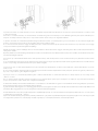
Avvertenza.
Con testa termostatica installata sul corpo valvola, nel periodo estivo per
evitare carichi eccessivi sulla guarnizione di tenuta del vitone termostatico con
il conseguente rischio di impuntamenti e bloccaggi, è opportuno posizionare
la manopola della testa termostatica nella posizione di massima apertura,
contraddistinta dal simbolo .
Calotta
Asta
Molla
Guarnizione
O-Ring
Corpo
In caso di malfunzionamento del vitone è
possibile sostituire l’anello O-Ring dell’asta,
svitando la calotta mediante l’utilizzo di una
chiave esagonale da 11 mm.
R400
Se il problema persiste è inoltre possibile sostituire il
vitone completo mediante l’utilizzo dell’apposita
chiave R400.
Warning.
With thermostatic head installed on the valve body, to avoid excessive loads on
the seal gasket of the thermostatic bonnet (with the resulting risk of jamming and
locking) during the summer, it is recommended to place the handwheel of the
thermostatic head in the fully open position, marked by the symbol .
Nut
Stem
Spring
Gasket
O-Ring
Body
In case of malfunction of the valve it is possible to
replace the O-ring, by unscrewing the nut using
an hexagonal wrench 11 mm
R400
If the problem persists is also possible to replace the
complete bonnet using the appropriate key R400.
Montaggio delle teste termostatiche Giacomini
Montage de les têtes thermostatiques Giacomini
Montage des Giacomini Thermostatkopfs
Assembly of Giacomini thermostatic heads
Montaje del cabezal termostático Giacomini
Montagem das cabeças termostáticas Giacomini
Montage van de thermostatische regelelementen Giacomini
Монтаж термостатических головок Джакомини
-
 1
1
-
 2
2
-
 3
3
-
 4
4


in altre lingue
- English: Giacomini R437N Operating instructions
- français: Giacomini R437N Mode d'emploi
- español: Giacomini R437N Instrucciones de operación
- Deutsch: Giacomini R437N Bedienungsanleitung
- Nederlands: Giacomini R437N Handleiding
- português: Giacomini R437N Instruções de operação
Documenti correlati
-
Giacomini R402TG Istruzioni per l'uso
-
-
-
-
-
-
-
-
-