Fadini nupi66 Instructions Manual
- Categoria
- Gate Opener
- Tipo
- Instructions Manual

NUPI 66
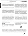
KIT pistone oleodinamico per cancelli a battente con ante no 2,5 m
Ipag.
l'apricancello
FADINI
l'apricancello
FADINI
1 - 8IT Libretto di istruzioni pag.
9 - 16GB Instructions manual pages
17 - 24FR Notice d’instructions page
EN 13241
EN 12453
EN 12445
istr_nupi66_IT.ai 1 27/06/2023 16:09:27

2
AVVERTENZE GENERALI PER LA SICUREZZA DELLE PERSONE
GRAZIE
Vi ringraziamo per aver deciso di acquistare un prodotto Fadini.
Vi invitiamo a leggere attentamente queste istruzioni prima di iniziare
a usare il dispositivo. Le istruzioni contengono informazioni
importanti che vi aiuteranno a trarre il meglio da questo dispositivo e
vi garantiranno altresì sicurezza in fase di installazione, uso e
manutenzione del dispositivo. Conservare questo manuale in un
luogo pratico, in modo da poterlo sempre consultare e garantire un
utilizzo sicuro e adeguato del dispositivo.
INTRODUZIONE
Questa automazione è stata progettata per un utilizzo esclusivo per
quanto indicato in questo libretto, con gli accessori di sicurezza e di
segnalazione minimi richiesti e con i dispositivi Fadini. □ Qualsiasi altra
applicazione non espressamente indicata in questo libretto potrebbe
provocare disservizi o danni a cose e persone. □ Meccanica Fadini S.r.l.
non è responsabile per eventuali danni derivati da usi impropri e non
specicatamente indicati in questo libretto; non risponde inoltre di
malfunzionamenti derivati dall'uso di materiali e/o accessori non
indicati dalla ditta stessa. □ La ditta costruttrice si riserva di apportare
modiche ai propri prodotti senza preavviso. □ Tutto quanto non
espressamente indicato in questo manuale di istruzioni non è
permesso.
PRIMA DELL'INSTALLAZIONE
Prima di qualsiasi intervento valutare l'idoneità dell'ingresso da
automatizzare, nonché la sua condizione e la struttura. □ Accertarsi
che non si verichino situazioni di impatto, schiacciamento,
cesoiamento, convogliamento, taglio, uncinamento e sollevamento,
tali da poter pregiudicare la sicurezza delle persone. □ Non installare il
prodotto nelle vicinanze di fonti di calore ed evitare il contatto con
sostanze inammabili. □ Tenere lontano dalla portata di bambini
qualsiasi dispositivo (trasmettitori, lettori di prossimità, selettori, ecc.)
atto ad avviare l'automazione. □ Il transito nella zona di luce di
passaggio deve avvenire unicamente con l'automazione ferma. □ Non
consentire a bambini e/o persone di stazionare nei pressi
dell'impianto con l'automazione in movimento. □ Per garantire un
livello adeguato di sicurezza dell'impianto è necessario utilizzare
fotocellule, bordi sensibili, spire magnetiche e sensori di presenza per
mettere in sicurezza l'intera area interessata al movimento del
cancello. □ Servirsi di strisce giallo-nere o di adeguati segnali per
identicare i punti pericolosi dell'installazione. □ Togliere sempre
l'alimentazione elettrica all'impianto se si eettuano interventi di
manutenzione e/o pulizia. □ In caso di asportazione dell’attuatore,
non tagliare i li elettrici, ma toglierli dalla morsettiera allentando le
viti di serraggio dentro la scatola di derivazione.
INSTALLAZIONE
L'intera installazione deve essere eettuata da personale tecnico
qualicato, in osservanza della Direttiva Macchine 2006/42/CE e in
particolare le norme EN 12445 ed EN 12453. □ Vericare la presenza, a
monte dell'impianto, di un interruttore di linea 230 V - 50 Hz
magneto-termico dierenziale da 0,03 A. □ Utilizzare corpi di prova
idonei per le prove di funzionamento nella rilevazione della presenza,
in prossimità o interposti, ai dispositivi di sicurezza come fotocellule,
bordi sensibili, ecc.
□ Eseguire una attenta analisi dei rischi, utilizzando appositi strumenti
di rilevazione di impatto e schiacciamento del bordo principale di
apertura e chiusura, secondo quanto indicato nella normativa EN
12445. □ Individuare la soluzione più indicata per eliminare o ridurre
tali rischi. □ Nel caso in cui il cancello da automatizzare fosse dotato di
un ingresso pedonale, è opportuno predisporre l'impianto in maniera
tale da interdire il funzionamento del motore quando l'ingresso
pedonale è utilizzato. □ Fornire indicazioni sulla presenza
dell'impianto realizzato con l'applicazione di targhe segnaletiche con
marcatura CE sul cancello. □ L'installatore è tenuto ad informare ed
istruire l'utilizzatore nale circa l'uso corretto dell'impianto; ciò
avviene rilasciandogli una documentazione rmata denita fascicolo
tecnico, comprensiva di: schema e componenti dell'impianto, analisi
dei rischi, verica degli accessori di sicurezza, verica delle forze di
impatto e segnalazione dei rischi residui.
INDICAZIONI PER L'UTILIZZATORE FINALE
L'utilizzatore nale è tenuto a prendere visione e ricevere informazioni
unicamente per quanto concerne il funzionamento dell'impianto e
diviene lui stesso responsabile del corretto uso. □ Deve stipulare un
contratto di manutenzione ordinaria e straordinaria (su chiamata) con
l'installatore/manutentore. □ Qualsiasi intervento di riparazione deve
essere eettuato solo da personale tecnico qualicato. □ Conservare
sempre il presente manuale di istruzioni.
AVVERTENZE PER IL BUON FUNZIONAMENTO DELL'IMPIANTO
Per una resa ottimale dell’impianto nel tempo e secondo le normative
di sicurezza, è necessario eseguire una corretta manutenzione e un
adeguato monitoraggio dell’intera installazione per l’automazione,
per le apparecchiature elettroniche installate e anche per i cablaggi
ad esse eettuate. □ Tutta l’installazione deve essere eseguita da
personale tecnico qualicato, compilando il documento di verica e
collaudo ed il registro di manutenzione indicato nel libretto
normative di sicurezza (da richiedere o scaricare dal sito
www.fadini.net/supporto/downloads). □ Per l'automazione è
consigliato un controllo di manutenzione almeno ogni 6 mesi, mentre
per apparecchiature elettroniche e sistemi di sicurezza un controllo
mensile di manutenzione. □ Meccanica Fadini S.r.l. non è responsabile
dell'eventuale inosservanza della buona tecnica di installazione e/o
del non corretto mantenimento dell'impianto.
SMALTIMENTO DEI MATERIALI
Gli involucri dell’imballo come cartone, nylon, polistirolo, ecc.
possono essere smaltiti eettuando la raccolta dierenziata (previa
verica delle normative vigenti nel luogo dell'installazione in materia
di smaltimento riuti). Elementi elettrici, elettronici e batterie
possono contenere sostanze inquinanti: rimuovere e adare tali
componenti a ditte specializzate nel recupero dei riuti, come
indicato nella direttiva 2012/19/UE. Vietato gettare nei riuti materiali
nocivi per l’ambiente.
Meccanica Fadini S.r.l.
Direttore Responsabile
DICHIARAZIONE DI CONFORMITÀ CE del costruttore:
Meccanica Fadini S.r.l. (Via Mantova, 177/A - 37053 Cerea - VR - Italy) dichiara sotto la propria responsabilità che Nupi 66 è
conforme alla direttiva macchine 2006/42/CE, inoltre: viene commercializzato per essere installato come "impianto
automatizzato", con accessori e componenti originali indicati dalla Ditta Costruttrice. L'automazione, secondo i termini di legge,
è una "macchina" e pertanto devono essere applicate dall'Installatore tutte le norme di sicurezza. L'installatore stesso è tenuto a
rilasciare la propria Dichiarazione di Conformità. La ditta costruttrice non si assume responsabilità circa l'uso improprio del
prodotto. Il prodotto risulta conforme alle seguenti normative speciche: Analisi dei Rischi e successivo intervento per eliminarli
EN 12445 ed EN 12453, Direttiva Bassa Tensione 2014/35/UE, Direttiva Compatibilità Elettromagnetica 2014/30/UE. Al ne di
certicare il prodotto il Costruttore dichiara sotto la propria responsabilità il rispetto della NORMATIVA DI PRODOTTO
EN 13241-1.
Testato e certicato: marcatura con prove di tipo ITT PDC N. 2391-2008.
Italiano
KIT pistone oleodinamico per cancelli a battente
con ante no 2,5 m
NUPI 66
istr_nupi66_IT.ai 2 27/06/2023 16:09:33

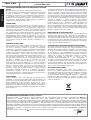
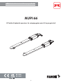
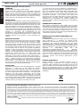
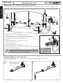
1 - Attacco dello stelo sull’anta (OPTIONAL)
2 - Attacco dello stelo sull’anta con N° 4 seeger e N° 2 spinotti
3 - N° 2 Nupi 66
GENERALITÀ SUL PRODOTTO
L'attuatore oleodinamico NUPI 66 è un pistone idraulico con blocco in chiusura per ante a battente che non superino i 2 metri di
lunghezza anta, da applicare al pilastro e sull'anta, e come particolarità non presenta la necessità di nessuna regolazione di registri
di massima e minima spinta, poiché tali funzioni sono eseguite elettronicamente dal programmatore ELPRO 7 RP.
COMPONENTI E ACCESSORI DEL SOLO PISTONE FORNITI NEL KIT
4 - N° 2 chiavi di sblocco
5 - N° 2 cofani di protezione
6 - N° 2 piastre di attacco forate
Fig. 1
Italiano
3
3
6
5
4
2
1
KIT pistone oleodinamico per cancelli a battente
con ante no 2,5 m
NUPI 66
istr_nupi66_IT.ai 3 27/06/2023 16:09:34

21
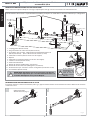
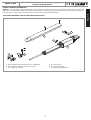
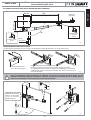
PREDISPOSIZIONE IMPIANTO ELETTRICO E ACCESSORI
Prima di installare il pistone Nupi 66 si consiglia di predisporre tutti gli accessori di sicurezza e di comando minimi.
1 - Lampeggiatore (fornito nel kit)
2 - Programmatore con radio innesto (forniti nel kit)
3 - Interruttore di linea 230 V - 50 Hz magneto-termico dierenziale da
0,03 A (non fornito) - (oltre i 100 m cavo di sezione 2,5 mm²)
4 - Fotocellula ricevitore (fornita nel kit una sola coppia)
5 - Nupi 66
6 - Fotocellula trasmettitore (fornita nel kit una sola coppia)
7 - Selettore a chiave (fornito nel kit)
8 - Colonnetta fotocellule
9 - Battuta di apertura (obbligatoria, non fornita)
10 - Battuta di chiusura dell'anta (obbligatoria, non fornita)
11 - Elettroserratura per ante oltre i 2 metri di lunghezza (non fornita nel kit)
12 - Trasmettitore (fornito nel kit)
230 V - 50 Hz ± 10%
4x1 mm²
4x1,5 mm²
4x1 mm²
2x1 mm²
2x1 mm²
2x1 mm²
RG58
1
2x1 mm²
2
3
4
5
6
6
8
8
5
9
9
4
7
10
12
11
4x1,5 mm²
Fig. 2
Fig. 3
4x1,5 mm²
Vedere operazioni
sblocco manuale (Fig. 7)
Il cavo elettrico di
alimentazione deve
essere libero per
tutta la corsa di
apertura e chiusura
dell'anta.
!
Schema indicativo di massima: è responsabilità dell’installatore predisporre in modo idoneo e corretto le tubazioni per i collegamenti.
4x1 mm²
Italiano
4
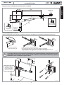
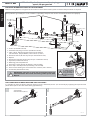
IMPORTANTE: le battute di arresto anta in apertura e in chiusura
sono molto importanti per il corretto funzionamento e la
sicurezza dell’impianto con il pistone Nupi 66.
!
PRIME MANOVRE PER FAR FUORIUSCIRE LO STELO
È possibile muovere lo stelo manualmente (vedi Fig. 3) oppure elettricamente con alimentazione elettrica. Muovere lo stelo no
a metà corsa circa.
KIT pistone oleodinamico per cancelli a battente
con ante no 2,5 m
NUPI 66
istr_nupi66_IT.ai 4 27/06/2023 16:09:34

Fig. 4
Fig. 5
Fig. 6
Misura determinata
della quota B (Fig. 4)
PREPARAZIONE DEGLI ATTACCHI
Saldare anzitempo gli attacchi anteriore e posteriore alle piastre di rinforzo (non in dotazione), livellandoli a bolla (Fig. 5).
Si consiglia di ssare provvisoriamente il pistone Nupi 66 al cancello, livellandolo a bolla, mediante morsetti,
quindi sbloccare ed eseguire alcune manovre manuali di apertura e chiusura per vericare che le quote di
installazione siano corrette per un’apertura di 90°.
!
QUOTE DI INSTALLAZIONE PER APERTURA VERSO L’INTERNO
Italiano
Piastra metallica di rinforzo (optional).
Per installazioni pesanti si consiglia di adeguare il rinforzo
alla tipologia dell'anta, mentre per ante leggere pannellate in alluminio
o legno eseguire il ssaggio con viti passanti e contropiastre.
90°
Livellare in tutte le
direzioni il pistone
prima di installarlo
denitivamente.
Attacco dello
stelo sull’anta
Battuta di
apertura
Battuta di
chiusura
90°
B=130 mm
80
A=130 970
Lama di attacco
al pilastro
5
KIT pistone oleodinamico per cancelli a battente
con ante no 2,5 m
NUPI 66
istr_nupi66_IT.ai 5 27/06/2023 16:09:34

Italiano
DATI TECNICI
PISTONE OLEODINAMICO
Portata pompa idraulica - P5 1,4 l/min
Pressione d'esercizio 10 atm
Velocità lineare apertura/chiusura ~15 mm/s
Forza 3.100 N
Tipo di olio Oil Fadini - cod. 708L
Corsa utile stelo 275 mm
Diametro stantuo 45 mm
Diametro stelo 16 mm
Temperatura di esercizio -20 °C +80 °C [A]
Peso completo pistone con accessori 8 kg
Peso max singola anta 400 kg
Lunghezza max singola anta 2,5 m
Grado di protezione IP 67
Misure d'ingombro (lung. x larg. x alt.) 1.240x86x86 mm
[A]: -40 °C con accessori optional specici (Rif. Catalogo Generale).
NOTA: Oltre i 2,0 m è sempre consigliabile l’uso dell’elettroserratura.
MOTORE ELETTRICO
Potenza resa 0,18 kW (0,25 CV)
Tensione di alimentazione 230 Vac
Frequenza 50 Hz
Corrente assorbita 1,2 A
Potenza assorbita 250 W
Condensatore 12,5 μF
Velocitá rotazione motore 1.350 rpm
Servizio intermittente S3
Classe H
Cavo elettrico essibile CEI 20- 52 -
FROR 450/750 V
PRESTAZIONI
Frequenza di utilizzo intensivo
Ciclo di servizio 18 s apertura - 20 s pausa - 20 s chiusura - 20 s pausa
Tempo di un ciclo completo 78 s
Cicli completi apertura - pausa - chiusura - pausa N° 50/ora
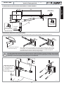
corsa 275
1.240 mm
1.240
86
86
83
60
48
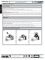
Fig. 7
Fig. 8
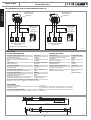
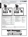
COLLEGAMENTI ELETTRICI AL PROGRAMMATORE ELPRO 7 RP
Comune
Fase
Fase
Morsettiera di
alimentazione
NUPI 66
Elpro 7 RP
Condensatore
di spunto
12,5 μF
in dotazione
230 V - 50 Hz
morsetti alimentazione
motore M1
(quello che apre per primo)
13 11 12
Comune
Fase
Fase
Morsettiera di
alimentazione
NUPI 66
Elpro 7 RP
Condensatore
di spunto
12,5 μF
in dotazione
230 V - 50 Hz
morsetti alimentazione
motore M2
16 14 15
6
KIT pistone oleodinamico per cancelli a battente
con ante no 2,5 m
NUPI 66
istr_nupi66_IT.ai 6 27/06/2023 16:09:35

da consegnare all’utilizzatore nale dell’impianto
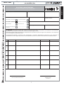
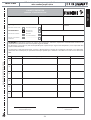
REGISTRO DI MANUTENZIONE
consegnare all’utilizzatore nale dell’impianto
Indirizzo impianto:
Tipo di installazione:
Cancello scorrevole
Basculante
N°
1
2
3
4
5
6
Data intervento
Timbro e rma
tecnico installatore/manutentore
Firma per accettazione
utilizzatore nale
committente
Tecnico manutentore Utilizzatore naleDescrizione intervento
Portone ad impacco
laterale
Cancello a battente
Portone a libro
Dissuasore
.............................
Barriera stradale
Modello attuatore:
Dimensioni dell’anta:
Peso singola anta: Data di installazione:
Quantità dei
modelli installati:
Manutentore: Data:
ATTENZIONE: questo documento deve contenere gli interventi ordinari e straordinari di installazione, manutenzione,
riparazione e le modiche di intervento svolte con ricambi originali Fadini.
Questo documento, come tale, deve essere disponibile alle ispezioni da parte di organismi autorizzati, e una copia deve
essere consegnata all’utilizzatore nale.
L’installatore/manutentore garantisce sulla funzionalità e sicurezza dell’impianto solamente se gli interventi di
manutenzione sono eseguiti da personale tecnico qualicato da lui incaricato e concordato con l'utilizzatore nale.
X
Italiano
7
KIT pistone oleodinamico per cancelli a battente
con ante no 2,5 m
NUPI 66
istr_nupi66_IT.ai 7 27/06/2023 16:09:35

Italiano
Fig. 9
8
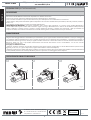
GUIDA ALL’USO (per l’utilizzatore nale)
• Il transito nel passaggio interessato dal cancello deve avvenire unicamente con l'automazione ferma; posizionarsi ad una adeguata
distanza di sicurezza durante il movimento di apertura e/o chiusura del cancello.
• Non toccare nessun componente dell’impianto mentre l’automatismo è in movimento.
• Non consentire a bambini e/o persone di stazionare nei pressi dell'impianto con l'automazione in movimento.
• Tenere lontano dalla portata di bambini qualsiasi dispositivo atto ad avviare l'automazione (trasmettitori, lettori di prossimità, selettori a
chiave, ecc.).
• Non utilizzare l’automatismo in presenza di anomalie dell’impianto.
SMALTIMENTO DEI MATERIALI: gli involucri dell’imballo come cartone, nylon, polistirolo, ecc. possono essere smaltiti eettuando la
raccolta dierenziata (previa verica delle normative vigenti nel luogo dell'installazione in materia di smaltimento riuti). Elementi
elettrici, elettronici e batterie possono contenere sostanze inquinanti: rimuovere e adare tali componenti a ditte specializzate nel
recupero dei riuti, come indicato nella direttiva 2012/19/UE. Vietato gettare nei riuti materiali nocivi per l’ambiente.
AVVERTENZE
Per una resa ottimale dell’impianto nel tempo e secondo le normative di sicurezza, è necessario eseguire una corretta manutenzione e un
adeguato monitoraggio dell’intera installazione per l’automazione, per le apparecchiature elettroniche installate e anche per i cablaggi ad
esse eettuate. Tutta l’installazione deve essere eseguita da personale tecnico qualicato. Per l'automazione è consigliato un controllo di
manutenzione almeno ogni 6 mesi, mentre per apparecchiature elettroniche e sistemi di sicurezza un controllo mensile di manutenzione.
Meccanica Fadini S.r.l. non è responsabile dell'eventuale inosservanza della buona tecnica di installazione e/o del non corretto
mantenimento dell'impianto.
Consigli per l’utilizzatore nale:
• eliminare eventuale materiale che potrebbe depositarsi nelle apparecchiature ed impedirne il corretto funzionamento (resti di insetti,
fogliame, piccoli sassi, ecc.); prima di procedere, togliere alimentazione elettrica dall’impianto;
• eettuare regolarmente la pulizia delle apparecchiature servendosi unicamente di un panno umido. Non utilizzare sostanze inammabili
o alcool, diluenti, benzene: tali sostanze potrebbero provocare esplosioni e/o danneggiare l’intero impianto.
MANUTENZIONE
OPERAZIONE DI SBLOCCO MANUALE
321
Direttiva 2012/19/UE
Smaltimento dei materiali
elettrici ed elettronici
VIETATO GETTARE NEI RIFIUTI
MATERIALI NOCIVI PER L’AMBIENTE
I
Via Mantova, 177/A - 37053 Cerea (VR) Italy
Ph. +39 0442 330422 Fax +39 0442 331054
KIT pistone oleodinamico per cancelli a battente
con ante no 2,5 m
NUPI 66
istr_nupi66_IT.ai 8 27/06/2023 16:09:35

NUPI 66
KIT with oil-hydraulic operators for swinging gates up to 2,5 m per gate leaf
9 - 16GB Instructions manual pages
l'apricancello
FADINI
l'apricancello
FADINI
9
EN 13241
EN 12453
EN 12445
istr_nupi66_GB.ai 1 27/06/2023 16:09:53

10
English
GENERAL WARNINGS FOR PEOPLE SAFETY
THANK YOU
Thank you for purchasing a Fadini product.
Please read these instructions carefully before using this
appliance. The instructions contain important information
which will help you get the best out of the appliance and
ensure safe and proper installation, use and maintenance.
Keep this manual in a convenient place so that you can always
refer to it for the safe and proper use of the appliance.
INTRODUCTION
This operator is designed for a specic scope of applications as
indicated in this manual, including safety, control and signaling
accessories as minimum required with Fadini equipment. □ Any
applications not explicitly included in this manual may cause
operation problems or damages to properties and people. □
Meccanica Fadini S.r.l. is not liable for damages caused by the
incorrect use of the equipment, or for applications not included
in this manual or for malfunctioning resulting from the use of
materials or accessories not recommended by the
manufacturer. □ The manufacturer reserves the right to make
changes to its products without prior notice. □ All that is not
explicitly indicated in this manual is to be considered not
allowed.
BEFORE INSTALLATION
Before commencing operator installation assess the suitability
of the access, its general condition and the structure. □ Make
sure that there is no risk of impact, crushing, shearing,
conveying, cutting, entangling and lifting situations, which
may prejudice people safety. □ Do not install near any source of
heat and avoid contacts with ammable substances. □ Keep all
the accessories able to turn on the operator (transmitters,
proximity readers, key-switches, etc) out of the reach of the
children. □ Transit through the access only with stationary
operator. □ Do not allow children and/or people to stand in the
proximity of a working operator. □ To ensure safety in the
whole movement area of a gate it is advisable to install
photocells, sensitive edges, magnetic loops and detectors. □
Use yellow-black strips or proper signals to identify dangerous
spots. □ Before cleaning and maintenance operations,
disconnect the appliance from the mains by switching o the
master switch. □ If removing the actuator, do not cut the
electric wires, but disconnect them from the terminal box by
loosening the screws inside the junction box.
INSTALLATION
All installation operations must be performed by a qualied
technician, in observance of the Machinery Directive
2006/42/CE and safety regulations EN 12453 - EN 12445. □
Verify the presence of a thermal-magnetic circuit breaker 0,03
A - 230 V - 50 Hz upstream the installation. □ Use appropriate
objects to test the correct functionality of the safety
accessories, such as photocells, sensitive edges, etc. □ Carry out
a risk analysis by means of appropriate instruments measuring
the crushing and impact force of the main opening and closing
edge in compliance with EN 12445. □ Identify the appropriate
solution necessary to eliminate and reduce such risks.
□ In case where the gate to automate is equipped with a
pedestrian entrance, it is appropriate to prepare the system in
such a way to prohibit the operation of the engine when the
pedestrian entrance is used. □ Apply safety nameplates with
CE marking on the gate warning about the presence of an
automated installation. □ The installer must inform and
instruct the end user about the proper use of the system by
releasing him a technical dossier, including: layout and
components of the installation, risk analysis, verication of
safety accessories, verication of impact forces and reporting
of residual risks.
INFORMATION FOR END-USERS
The end-user is required to read carefully and to receive
information concerning only the operation of the installation
so that he becomes himself responsible for the correct use of it.
□ The end-user shall establish a written maintenance contract
with the installer/maintenance technician (on -call). □ Any
maintenance operation must be done by qualied technicians.
□ Keep these instructions carefully.
WARNINGS FOR THE CORRECT OPERATION OF THE
INSTALLATION
For optimum performance of system over time according to
safety regulations, it is necessary to perform proper
maintenance and monitoring of the entire installation: the
automation, the electronic equipment and the cables
connected to these. □ The entire installation must be carried
out by qualied technical personnel, lling in the Maintenance
Manual indicated in the Safety Regulation Book (to be
requested or downloaded from the site
www.fadini.net/supporto/downloads). □ Operator:
maintenance inspection at least every 6 months, while for the
electronic equipment and safety systems an inspection at least
once every month is required. □ The manufacturer, Meccanica
Fadini S.r.l., is not responsible for non-observance of good
installation practice and incorrect maintenance of the
installation.
DISPOSAL OF MATERIALS
Dispose properly of the packaging materials such as
cardboard, nylon, polystyrene etc. through specializing
companies (after verication of the regulations in force at the
place of installation in the eld of waste disposal). Disposal of
electrical and electronic materials: to remove and dispose
through specializing companies, as per Directive 2012/19/UE.
Disposal of substances hazardous for the environment is
prohibited.
Meccanica Fadini S.r.l.
Director in charge
CE DECLARATION OF CONFORMITY of the manufacturer:
Meccanica Fadini S.r.l. (Via Mantova, 177/A - 37053 Cerea - VR - Italy) declares under own responsibility that: Nupi 66
complies with the 2006/42/CE Machinery Directive, and also that it is sold to be installed in an “automatic system”, along
with original accessories and components as indicated by the manufacturing company. An automatic gate operator is, by
law, a “machinery” and therefore the installer must t the equipment with all of the applicable safety norms. The installer is
also required to issue the installer’s Declaration of Conformity. The manufacturer is not liable for possible incorrect use of
the product. The product complies with the following specic norms: analysis of the risks and subsequent action to cure
them as per EN 12445 and EN 12453, Low Voltage Directive 2014/35/UE, Electromagnetic Compatibility 2014/30/UE. In
order to certify the product, the manufacturer declares under own responsibility the compliance with the EN 13241-1
PRODUCT NORMS.
Tested and certied: marking and type testing according to ITT PDC No. 2391-2008.
KIT with oil-hydraulic operators for swinging gates
up to 2,5 m per gate leaf
NUPI 66
istr_nupi66_GB.ai 2 27/06/2023 16:09:55

1 - Gate xing bracket with back plate (as an OPTION)
2 - Gate xing bracket with 4 circlips and 2 pins
3 - N° 2 x Nupi 66 actuators
PRODUCT GENERAL INFORMATION
NUPI 66 is an oil-hydraulic actuator tted with a locking device to hold the gates in closed position, suitable for gate leaves not
wider than 2 meters and designed to be mounted on to the gate and gate post. Its peculiar feature is that thrust power setting into
low and high is not by valves, being this function electronically controlled by ELPRO 7 RP.
ACTUATOR COMPONENTS AND FITTINGS INCLUDED IN THE KIT
4 - N° 2 release keys
5 - N° 2 protection covers
6 - N° 2 pre-bored xing plates
Pic. 1
English
11
3
6
5
4
2
1
KIT with oil-hydraulic operators for swinging gates
up to 2,5 m per gate leaf
NUPI 66
istr_nupi66_GB.ai 3 27/06/2023 16:09:55

ELECTRICAL WIRING AND LAYOUT OF THE ACCESSORIES
Before installing Nupi 66 arrange for the accessories to have control of the system and meet safety standards as required.
1 - Flasher (included in the kit)
2 - Controller with plug-in receiver (included in the kit)
3 - 230 V - 50 Hz - 0,03 A magneto-thermal circuit breaker
(not included) - (beyond 100 m, cable section 2,5 mm²)
4 - Photocell receiver (for the only one pair included in the kit)
5 - Nupi 66
6 - Photocell transmitter (for the only one pair included in the kit)
7 - Keyswitch (included in the kit)
8 - Mounting posts for photocells
9 - Gate stop in open position (mandatory, not included)
10 - Gate stop in closed position (mandatory, not included)
11 - Gate electric lock for gate leaves wider than 2 meters (not in the kit)
12 - Transmitter (included in the kit)
4x1 mm²
4x1,5 mm²
4x1 mm²
2x1 mm²
2x1 mm²
2x1 mm²
RG58
2x1 mm²
2
3
4
5
6
6
8
8
5
9
9
4
7
10
12
11
4x1,5 mm²
Pic. 2
Pic. 3
4x1,5 mm²
The electric cable is
to dangle without
sharp bending all
along gate travel on
opening and closing
cycles.
!
Merely indicative general layout : it is the installler’s responsibility to lay the tubes for the electrical connections most properly.
4x1 mm²
English
12
IMPORTANT: gate stops in open and closed gate positions are
fundamental for the correct functioning of the system with
Nupi 66.
!
FIRST OPERATIONS TO MOVE THE PISTON SHAFT OUTWARDS
It is possible to move the piston shaft out either by hand as indicated (see Pic. 3) or electrically by supplying the operator with
power. Either pull or drive the shaft halfway approximately.
230 V - 50 Hz ± 10%
21 See steps for
manual release (Pic. 7)
1
KIT with oil-hydraulic operators for swinging gates
up to 2,5 m per gate leaf
NUPI 66
istr_nupi66_GB.ai 4 27/06/2023 16:09:55

Pic. 4
Pic. 5
Pic. 6
This dimension depends
on distance B (Pic. 4)
PREPARATORY WORK WITH FIXING ACCESSORIES
First of all weld the front and rear xing brackets to the patch plates (not in the kit pack), perfectly levelled (Pic. 5).
It is advised that Nupi 66 be temporary xed to the gate, perfectly aligned, by means of clamps. Then override
the locking device and carry out a few manual cycles by opening and closing the gate to make sure the xing
geometry is correct and a proper 90° opening can so be achieved.
!
FIXING GEOMETRY WITH DISTANCES FOR THE GATES TO OPEN INWARDS
English
Metal patch plate to strengthen the xing point (optional). With heavy
installations it is recommended that the patch plate be adequate to the gate
type. With light gates made of aluminium sheeted panels or wood, counterplates
should be used to take the screws passing through.
90°
The actuator is to
be aligned in all
directions before
nal xing.
Shaft xing on
to the gate
Gate stop
in open
position
Gate stop in
closed position
90°
A=130 970
Plate for xing
on to gate post
13
B=130 mm
80
KIT with oil-hydraulic operators for swinging gates
up to 2,5 m per gate leaf
NUPI 66
istr_nupi66_GB.ai 5 27/06/2023 16:09:56

English
14
stroke 275
1.240 mm
1.240
86
86
83
60
48
Pic. 7
Pic. 8
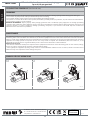
ELECTRICAL CONNECTIONS TO ELPRO 7 RP CONTROLLER
Common
Phase
Phase
Power supply
terminals
NUPI 66
Elpro 7 RP
Equipped
with
12,5 μF
start capacitor
230 V - 50 Hz
Power supply terminals
M1 motor
(opening rst)
13 11 12
Common
Phase
Phase
Power supply
terminals
NUPI 66
Elpro 7 RP
Equipped
with
12,5 μF
start capacitor
230 V - 50 Hz
Power supply terminals
M2 motor
16 14 15
TECHNICAL DATA
OIL-HYDRAULIC OPERATOR
Pump ow rate - P5 1,4 l/min
Working pressure 10 atm
Linear speed opening/closing ~15 mm/s
Thrust 3.100 N
Oil type Fadini Oil - code 708L
Piston stroke 275 mm
Piston diameter 45 mm
Piston shaft diameter 16 mm
Working temperature -20 °C +80 °C [A]
Operator weight, complete 8 kg
Single gate max. weight 400 kg
Single gate max. width 2,5 m
Protection standards IP 67
Overall dimensions (L x W x H) 1.240x86x86 mm
[A]: -40 °C with specic optional accessories (General Catalogue refers).
NOTE: an electric lock is always recommended beyond 2 m gate leaf
ELECTRIC MOTOR
Power 0,18 kW (0,25 HP)
Voltage 230 Vac
Frequency 50 Hz
Absorbed current 1,2 A
Absorbed power 250 W
Capacitor 12,5 μF
Motor revolutions 1.350 rpm
Intermittent service S3
Class H
Flexible electric cable CEI 20- 52 -
FROR 450/750 V
PERFORMANCE
Frequency of use intensive
Duty Cycle 18 s opening - 20 s dwell - 20 s closing - 20 s dwell
Time of one complete cycle 78 s
Complete cycles opening - dwell - closing - dwell N° 50/hour
KIT with oil-hydraulic operators for swinging gates
up to 2,5 m per gate leaf
NUPI 66
istr_nupi66_GB.ai 6 27/06/2023 16:09:56

English
15
MAINTENANCE RECORD
hand over to the end user of the installation
Installation address:
Installation type:
Sliding gate
Over-head door
N°
1
2
3
4
5
6
Service date
Stamp and signature
installation technician/maintainer
Signed for acceptance
end user
buyer
Technical maintainer End user/sService description
Lateral folding
door
Swinging gate
Folding door
Bollard
.............................
Road barrier
Operator model:
Dimensions per gate leaf:
Weight per gate leaf: Installation date:
Quantity of models
installed:
Maintainer: Date:
NOTE WELL: this document must record any ordinary and extraordinary services including installation, maintenance,
repairs and replacements to be made only by using Fadini original spare parts.
This document, for the data included in it, must be made available to authorized inspectors/ocers, and a copy of it must
be handed over the end user/s.
The installer/maintainer are liable for the functionalities and safety features of the installation only if maintenance is
carried on by qualied technical people appointed by themselves and agreed upon with the end user/s.
X
hand over to the end user of the installation
KIT with oil-hydraulic operators for swinging gates
up to 2,5 m per gate leaf
NUPI 66
istr_nupi66_GB.ai 7 27/06/2023 16:09:56

English
16
Pic. 9
MANUAL RELEASE OPERATIONS
321
GUIDANCE FOR PROPER USE (for the end user)
• Transit across the gate is allowed only if motor is stopped; stand at safe distance during opening and/or closing cycles of the gate.
• Do not touch any components of the system while the operator is working.
• Do not allow children and/or people to stand in the proximity of a working operator.
• Keep all the accessories able to turn on the operator (transmitters, proximity readers, key-switches, etc.) out of the reach of the children.
• Do not run the system in case of anomalies.
DISPOSAL OF MATERIAL: dispose properly of the packaging materials such as cardboard, nylon, polystyrene etc. through specializing
companies (after verication of the regulations in force at the place of installation in the eld of waste disposal). Disposal of electrical and
electronic materials: to remove and dispose through specializing companies, as per Directive 2012/19/UE. Disposal of substances
hazardous for the environment is prohibited.
WARNINGS
For optimum performance of system over time according to safety regulations, it is necessary to perform proper maintenance and
monitoring of the entire installation: the automation, the electronic equipment and the cables connected to these. The entire installation
must be carried out by qualied technical personnel. Operator: maintenance inspection at least every 6 months, while for the electronic
equipment and safety systems an inspection at least once every month is required. The manufacturer, Meccanica Fadini S.r.l., is not
responsible for non-observance of good installation practice and incorrect maintenance of the installation.
Advice for the end user:
• clear the site of materials that may have deposited in the equipment and hinder its correct functioning (such as rests of insects, foliage,
stones, etc.); before carrying out this operation, switch o voltage supply;
• clean regularly the equipment by using a damp cloth. Do not use ammable substances such as alcohol, solvents or benzene: these
substances may cause explosions and/or damage the system.
MAINTENANCE
KIT with oil-hydraulic operators for swinging gates
up to 2,5 m per gate leaf
NUPI 66
Via Mantova, 177/A - 37053 Cerea (VR) Italy
Ph. +39 0442 330422 Fax +39 0442 331054
[email protected] - www.fadini.net
GB 2012/19/UE Directive
Re. disposal of electric
and electronic waste
DISPOSE PROPERLY OF MATERIALS
ARMFUL TO THE ENVIRONMENT
20230616
istr_nupi66_GB.ai 8 27/06/2023 16:09:57

NUPI 66
KIT vérin hydraulique pour portails à battant avec vantaux jusqu’à 2,5 m
17 - 24FR Notice d’instructions pages
l'apricancello
FADINI
l'apricancello
FADINI
17
EN 13241
EN 12453
EN 12445
istr_nupi66_FR.ai 1 27/06/2023 16:10:15

18
Français
AVERTISSEMENTS DE SECURITE AUX USAGERS
NOUS VOUS REMERCIONS
Nous vous remercions d'avoir acheté un produit Fadini.
Veuillez lire attentivement ces instructions avant d’utiliser l'appareil.
Ces instructions sont des informations utiles vous permettant de
mieux exploiter cet appareil,et vous assurer une installation, une
utilisation et un entretien sécurisés et adéquats. Veuillez bien garder
ce manuel et toujours vous y référ pour une utilisation sécurisée et
adéquate de l'appareil.
INTRODUCTION
Cet automatisme a été conçu pour une utilisation qui respecte ce qu'il
y a indiqué dans ce livret, avec les accessoires de sécurité et de
signalisation minimaux demandés et avec les dispositifs Fadini. □
Toute autre application pas expressément indiquée dans ce livret
pourrait provoquer des dysfonctionnements ou des dommages à
choses et personnes. □ Meccanica Fadini n'est pas responsable
d'éventuels dommages provoqués par une utilisation impropre et non
spéciquement indiquée dans ce livret. En outre, elle n'est pas
responsable des dysfonctionnements causés par l'usage de matériels
ou accessoires non recommandés par le fabricant. □ L'entreprise de
construction se réserve le droit d'apporter des modications aux
propres produits sans préavis. □ Tout ce qui n'est pas prévue dans
cette notice d'installation n'est pas permis.
INSTRUCTIONS A SUIVRE AVANT L'INSTALLATION
Contrôler avant toute intervention que l'entrée soit adaptée à
l'automatisation, ainsi que ces conditions et la structure. □
Assurez-vous qu'il n’y ait pas des risques d'impact, écrasement,
cisaillement, convoyage, entraînement et enlèvement, tells qu'on
pourrait aecter la sécurité des personnes. □ Installer l'automatisme
loin de tout sources de chaleur et éviter le contact avec substances
inammables. □ Garder tout dispositifs de contrôle automatisme
(émetteurs, lecteurs de proximité, sélecteurs etc) hors de la portée des
enfants. □ Transiter à travers la zone du mouvement du portail
seulement lorsque l'automatisme est fermé. □ An de garantir un
niveau de sécurité adéquat de l'installation il est nécessaire utiliser
photocellules, listeaux sensibles, spires magnétiques, détecteurs de
masse métalliques, en assurant la sécurité de tout l'aire de
mouvement du portail. □ Identier les points dangereux de
l'installation en l'en indiquant avec bandes jaune-noir ou autres
signaux appropriés. □ Couper l'alimentation avant toute intervention
d'entretien ou nettoyage de l'installation. □ Dans le cas ou on doit
enlever l’opérateur du portail, ne pas couper les ls électriques; mais
débranchez-les en desserrant les vis du bornier.
L'INSTALLATION
Toute l'installation doit être accomplie par personnel technique
qualié et autorisé, conformément à la directive Machines 2006/42/CE
et, notamment, aux normes EN 12445 et EN 12453. □ Vérier la
présence en amont de l'installation d'un interrupteur diérentiel
magnétothermique de 0,03 A de courant 230 V - 50 Hz. □ Utiliser des
objets approprié pour eectuer les tests de fonctionnement des
photocellules, détecteurs des masses métalliques, listeaux sensibles,
etc.
□ Eectuer une analyse des risques, en utilisant instruments de
détection de l'impact et écrasement du bord principale d’ouverture et
fermeture, conformément aux normes EN 12445. □ Dénir les
solutions appropriées pour éliminer ou réduire tels risques. □ Dans le
cas où le portail à automatiser aurait doué d'une entrée piétonne, il
serait bon d'accomplir l'installation de façon que le moteur ne
fonctionne pas lorsque l'entrée piéton est utilisé. □ Fournir des
indications concernant la position de l’installation en appliquant sur
le portail des plaquettes de signalisation marquée CE. □ L'installateur
doit informer l'utilisateur sur le fonctionnement correct du système,
en lui remettant le dossier technique signé, incluant: le schéma et les
éléments composants l'installation, l'analyse des risques, la
vérication des accessoires de sécurité, la vérication de la force
d'impact et la déclaration des risques résiduels.
INDICATIONS POUR L'UTILISATEUR FINAL
L'utilisateur doit consulter et recevoir information relative au
fonctionnement de l'installation et il devient lui-même responsable
du bon usage du système. □ Il faut qu'il conclue un contrat d'entretien
ordinaire et extraordinaire (sur appel) avec l'installateur/réparateur. □
Toute l’intervention d'entretien doivent être accompli par des
techniciens qualiés. □ Conserver toujours la notice d'installation.
AVERTISSEMENTS POUR LE FONCTIONNEMENT CORRECT DE
L'INSTALLATION
Pour que l’installation fonctionne correctement de façon durable et
conformément aux normes de sécurité en vigueur, vous devez faire
eectuer un entretien correct et le monitorage de toute l’installation
au niveau de l’automation, des appareils électroniques installés et des
câblages qui y sont branchés. □ Toute l'installation doit être eectuée
par un technicien qualié, qui doit remplir le Manuel d'Entretien
indiqué dans le Livret des Normes (à demander ou télécharger sur le
site www.fadini.net/supporto/downloads). □ L'automation: contrôle
d'entretien tous les 6 mois au moins, tandis que le contrôle d'entretien
des appareils électroniques et systèmes de sécurité doit être accompli
une fois par mois au moins. □ Meccanica Fadini S.r.l. n'est pas
responsable de l'éventuel non-respect des règles de bonne technique
d'installation et/ou de l'entretien incorrect du système.
RAMASSAGE DES MATERIAUX
Les éléments d'emballage, tels que le carton, nylon, polystyrène, etc.
peuvent être recyclés avec le collecte séparé (en vériant la
réglementation en vigueur dans le pays où le dispositif est monté).
Les composants électriques et électroniques, les batteries peuvent
contenir des substances polluantes: enlever et coner tels
composants aux sociétés chargées du traitement et de l’élimination
des déchets, dans le respect de la directive 2012/19/UE. Ne pas jeter
déchets nuisibles à l'environnement.
Meccanica Fadini S.r.l.
Directeur général
DECLARATION DE CONFORMITE CE:
Meccanica Fadini S.r.l. (Via Mantova, 177/A - 37053 Cerea - VR - Italy) déclare sous sa propre responsabilité que Nupi 66 est conforme à la
directive machines 2006/42/CE, en outre: est commercialisée pour être installée comme “installation automatisée”, avec les accessoires et les
composants originaux indiqués par l’entreprise de construction. Aux termes de la loi, l’automatisation est une “machine” et l’installateur doit
donc appliquer toutes les normes de sécurité. L’installateur doit délivrer sa déclaration de conformité. L’entreprise de construction décline
toute responsabilité sur l’utilisation impropre du produit. Le produit est conforme aux normes spéciques suivantes: analyse des risques et
intervention suivante pour les éliminer EN 12445 et EN 12453; Directive basse tension 2014/35/UE; Directive compatibilité électromagnétique
2014/30/UE. An de cértier le produit le producteur déclare sous sa propre résponsabilité la conformité à la NORME PRODUIT EN 13241-1.
Testé et certié: marquage avec essais de type ITT PDC N. 2391-2008.
KIT vérin hydraulique pour portails à battant
avec vantaux jusqu’à 2,5 m
NUPI 66
istr_nupi66_FR.ai 2 27/06/2023 16:10:17

1 - Pièce de xation de la tige sur le vantail (OPTION)
2 - Pièce de xation de la tige sur le vantail par N° 4 seeger et
N° 2 goupilles
3 - N° 2 Nupi 66
CARACTERISTIQUES DU PRODUIT
L’automatisme hydraulique NUPI 66 est un vérin hydraulique avec blocage à la fermeture pour vantaux à battant qui ne dépassent
pas les 2 mètres de largeur par vantail. Il doit être appliqué sur le pilier et sur le vantail et il n'a pas besoin du réglage des registres
de poussée max. et min. puisque ces fonctions sont suivies électroniquement par le programmateur ELPRO 7 RP.
COMPOSANTS ET ACCESSOIRES FOURNIS DANS LE KIT
4 - N° 2 clés de déverrouillage
5 - N° 2 carters de protection
6 - N° 2 plaques de xation trouées
Fig. 1
Français
19
3
6
5
4
2
1
KIT vérin hydraulique pour portails à battant
avec vantaux jusqu’à 2,5 m
NUPI 66
istr_nupi66_FR.ai 3 27/06/2023 16:10:18

PREPARATION DE L’INSTALLATION ELECTRIQUE ET DES ACCESSOIRES
Avant d'installer le Vérin Nupi 66, il est conseillé de préparer tous les accessoires de sécurité et de contrôle minimum.
4x1 mm²
4x1,5 mm²
4x1 mm²
2x1 mm²
2x1 mm²
2x1 mm²
RG58
2x1 mm²
2
3
4
5
6
6
8
8
5
9
9
4
7
10
12
11
4x1,5 mm²
Fig. 2
4x1,5 mm²
Le câble d'alimentation
électrique doit être libre
pour tout le mouvement
d'ouverture et de
fermeture du vantail.
!
Schéma indicatif de l’installation: l’installateur est responsable de la préparation correcte des tuyauteries pour les raccordements.
4x1 mm²
Français
20
IMPORTANT: les butées d’arrét d'ouverture et de fermeture du
vantail sont très importantes pour le bon fonctionnement et
la sécurité du système avec le piston Nupi 66.
!
PREMIERES MANOEUVRES POUR SORTIR LA TIGE
La tige peut être déplacée manuellement (voir Fig. 3) ou électriquement par alimentation électrique.
Déplacez la tige à mi-chemin.
230 V - 50 Hz ± 10%
1 - Lampe clignotante (fournie dans le kit)
2 - Programmateur avec radio enchable (fourni dans le kit)
3 - Interrupteur de ligne 230 V - 50 Hz magnéto-thermique diérentiel de
0,03 A (non fourni) - (au-déla de 100 m câble de section 2,5 mm²)
4 - Photocellule récepteur (une paire seulement dans le kit)
5 - Nupi 66
6 - Photocellule émetteur (une paire seulement dans le kit)
7 - Sélecteur à clé (fourni dans le kit)
8 - Potelet photocellules
9 - Butée d’ouverture (obligatoire, pas fournie)
10 - Butée de fermeture du vantail (obligatoire, pas fournie)
11 - Serrure électrique pour vantaux au-délà de 2 m de largeur (pas fournie dans le kit)
12 - Télécommande (fournie dans le kit)
21
Fig. 3
Voir les opérations de
déverrouillage manuel
(Fig. 7)
1
KIT vérin hydraulique pour portails à battant
avec vantaux jusqu’à 2,5 m
NUPI 66
istr_nupi66_FR.ai 4 27/06/2023 16:10:18
La pagina si sta caricando...
La pagina si sta caricando...
La pagina si sta caricando...
La pagina si sta caricando...
-
 1
1
-
 2
2
-
 3
3
-
 4
4
-
 5
5
-
 6
6
-
 7
7
-
 8
8
-
 9
9
-
 10
10
-
 11
11
-
 12
12
-
 13
13
-
 14
14
-
 15
15
-
 16
16
-
 17
17
-
 18
18
-
 19
19
-
 20
20
-
 21
21
-
 22
22
-
 23
23
-
 24
24


Fadini nupi66 Instructions Manual
- Categoria
- Gate Opener
- Tipo
- Instructions Manual
in altre lingue
- English: Fadini nupi66
- français: Fadini nupi66
Documenti correlati
-
Fadini dardo424-110Vac Instructions Manual
-
-
-
-
-
-
-
-
-