
IT
Elpro 37 HP
GB
FR
DE
Programmatore elettronico monofase - trifase con teleruttori di potenza e freno
elettronico per cancelli scorrevoli e automazioni con o senza necorsa (max 3 CV
monofase o 5 CV trifase).
Single-Three phase electronic control board with power contactors and
electronic brake for sliding gate and automatic systems with or without limit
switches (max 3 HP single-phase or 5 HP three-phase).
Programmateur electronique monophasé - triphasé avec telerupteurs de
puissance et frein electronique pour portails coulissants et automatismes avec ou
sans n de course (max 3 CV monophasé ou 5 CV triphasé).
Elektronische Steuerung, einphasig - dreiphasig mit Fernschalter und
Elektrobremse für Schiebetore, und Automationen mit oder ohne Endschalter
max 3 PS einphasig oder 5 PS dreiphasig).
IT - TELERUTTORI DI POTENZA
- FRENO ELETTRONICO
- FUNZIONE PASSO-PASSO
- UOMO PRESENTE
- APERTURA PEDONALE
- FUNZIONE OROLOGIO
- AUTOMATICO / SEMIAUTOMATICO
- USCITA ELETTROSERRATURA
- LUCE DI CORTESIA TEMPORIZZATA
- POSSIBILITÀ DI ESCLUDERE LAMPEGGIATORE IN PAUSA
GB - POWER CONTACTORS
- ELECTRONIC BRAKE
- STEP BY STEP FUNCTION
- HOLD-ON SWITCHED (DEADMAN) CONTROL
- PEDESTRIAN OPENING
- TIME CLOCK OPTION
- AUTOMATIC / SEMI-AUTOMATIC FUNCTION
- ADJUSTABLE COURTESY LIGHT TIME
- ELECTRIC LOCK OUTPUT
- FLASHING LAMP DURING DWELL TIME MADE ON/OFF SWITCHED ABLE
FR - TELERUPTEURS DE PUISSANCE
- FREIN ELECTRONIQUE
- FONCTION PAS A PAS
- HOMME MORT
- OUVERTURE PIETON
- FONCTION HORLOGE
- FONCTION AUTOMATIQUE / SEMIATUMATIQUE
- SORTIE SERRURE ELECTRIQUE
- LAMPE D’ECLAIRAGE TEMPORISEE
- POSSIBILITE D’ETEINDRE LA LAMPE DE SIGNALISATION EN PAUSE
DE - FERNSCHALTER
- ELEKTROBREMSE
- SCHRITTWEISE FUNKTION
- TOTMANNBETRIEB
- FUßGÄNGERFUNKTION
- UHR-FUNKTION
- AUTOMATISCH/HALBAUTOMATISCH
- ELEKTROSCHLOß AUSGANG
- HILFSBELEUCHTUNG TIMER
- MÖGLICHKEIT ZUM AUSSCHLUSS DER BLINKLEUCHTE BEI DER PAUSE
Dib. N. 7982 Via Mantova, 177/A - 37053 Cerea (VR) Italy
Ph. +39 0442 330422 Fax +39 0442 331054
[email protected] - www.fadini.net
istr_elpro37hp_IT.ai 1 20/06/2023 13:44:31

PROGRAMMATORE ELETTRONICO MONOFASE - TRIFASE
CON TELERUTTORI E FRENO ELETTRONICO
PER CANCELLI SCORREVOLI E AUTOMAZIONI CON O SENZA FINECORSA
Elpro 37 HP
IT
AVVERTENZE GENERALI PER LA SICUREZZA DELLE PERSONE
GRAZIE
Vi ringraziamo per aver deciso di acquistare un prodotto Fadini.
Vi invitiamo a leggere attentamente queste istruzioni prima di
iniziare a usare il dispositivo. Le istruzioni contengono
informazioni importanti che vi aiuteranno a trarre il meglio da
questo dispositivo e vi garantiranno altresì sicurezza in fase di
installazione, uso e manutenzione del dispositivo. Conservare
questo manuale in un luogo pratico, in modo da poterlo
sempre consultare e garantire un utilizzo sicuro e adeguato del
dispositivo.
INTRODUZIONE
Questa automazione è stata progettata per un utilizzo
esclusivo per quanto indicato in questo libretto, con gli
accessori di sicurezza e di segnalazione minimi richiesti e con i
dispositivi Fadini. □ Qualsiasi altra applicazione non
espressamente indicata in questo libretto potrebbe provocare
disservizi o danni a cose e persone. □ Meccanica Fadini S.r.l. non
è responsabile per eventuali danni derivati da usi impropri e
non specicatamente indicati in questo libretto; non risponde
inoltre di malfunzionamenti derivati dall'uso di materiali e/o
accessori non indicati dalla ditta stessa. □ La ditta costruttrice si
riserva di apportare modiche ai propri prodotti senza
preavviso. □ Tutto quanto non espressamente indicato in
questo manuale di istruzioni non è permesso.
PRIMA DELL'INSTALLAZIONE
Prima di qualsiasi intervento valutare l'idoneità dell'ingresso da
automatizzare, nonché la sua condizione e la struttura. □
Accertarsi che non si verichino situazioni di impatto,
schiacciamento, cesoiamento, convogliamento, taglio,
uncinamento e sollevamento, tali da poter pregiudicare la
sicurezza delle persone. □ Non installare il prodotto nelle
vicinanze di fonti di calore ed evitare il contatto con sostanze
inammabili. □ Tenere lontano dalla portata di bambini
qualsiasi dispositivo (trasmettitori, lettori di prossimità,
selettori, ecc.) atto ad avviare l'automazione. □ Il transito nella
zona di luce di passaggio deve avvenire unicamente con
l'automazione ferma. □ Non consentire a bambini e/o persone
di stazionare nei pressi dell'impianto con l'automazione in
movimento. □ Per garantire un livello adeguato di sicurezza
dell'impianto è necessario utilizzare fotocellule, bordi sensibili,
spire magnetiche e sensori di presenza per mettere in sicurezza
l'intera area interessata al movimento del cancello. □ Servirsi di
strisce giallo-nere o di adeguati segnali per identicare i punti
pericolosi dell'installazione. □ Togliere sempre l'alimentazione
elettrica all'impianto se si eettuano interventi di
manutenzione e/o pulizia. □ In caso di asportazione
dell’attuatore, non tagliare i li elettrici, ma toglierli dalla
morsettiera allentando le viti di serraggio dentro la scatola di
derivazione.
INSTALLAZIONE
L'intera installazione deve essere eettuata da personale
tecnico qualicato, in osservanza della Direttiva Macchine
2006/42/CE e in particolare le norme EN 12445 ed EN 12453. □
Vericare la presenza, a monte dell'impianto, di un interruttore
di linea 230 V - 50 Hz magneto-termico dierenziale da 0,03 A.
□ Utilizzare corpi di prova idonei per le prove di funzionamento
nella rilevazione della presenza, in prossimità o interposti, ai
dispositivi di sicurezza come fotocellule, bordi sensibili, ecc. □
Eseguire una attenta analisi dei rischi, utilizzando appositi
strumenti di rilevazione di impatto e schiacciamento del bordo
principale di apertura e chiusura, secondo quanto indicato
nella normativa EN 12445. □ Individuare la soluzione più
indicata per eliminare o ridurre tali rischi. □ Nel caso in cui il
cancello da automatizzare fosse dotato di un ingresso
pedonale, è opportuno predisporre l'impianto in maniera tale
da interdire il funzionamento del motore quando l'ingresso
pedonale è utilizzato. □ Fornire indicazioni sulla presenza
dell'impianto realizzato con l'applicazione di targhe
segnaletiche con marcatura CE sul cancello. □ L'installatore è
tenuto ad informare ed istruire l'utilizzatore nale circa l'uso
corretto dell'impianto; ciò avviene rilasciandogli una
documentazione rmata denita fascicolo tecnico,
comprensiva di: schema e componenti dell'impianto, analisi
dei rischi, verica degli accessori di sicurezza, verica delle
forze di impatto e segnalazione dei rischi residui.
INDICAZIONI PER L'UTILIZZATORE FINALE
L'utilizzatore nale è tenuto a prendere visione e ricevere
informazioni unicamente per quanto concerne il
funzionamento dell'impianto e diviene lui stesso responsabile
del corretto uso. □ Deve stipulare un contratto di
manutenzione ordinaria e straordinaria (su chiamata) con
l'installatore/manutentore. □ Qualsiasi intervento di
riparazione deve essere eettuato solo da personale tecnico
qualicato. □ Conservare sempre il presente manuale di
istruzioni.
AVVERTENZE PER IL BUON FUNZIONAMENTO
DELL'IMPIANTO
Per una resa ottimale dell’impianto nel tempo e secondo le
normative di sicurezza, è necessario eseguire una corretta
manutenzione e un adeguato monitoraggio dell’intera
installazione per l’automazione, per le apparecchiature
elettroniche installate e anche per i cablaggi ad esse eettuate.
□ Tutta l’installazione deve essere eseguita da personale
tecnico qualicato, compilando il documento di verica e
collaudo ed il registro di manutenzione indicato nel libretto
normative di sicurezza (da richiedere o scaricare dal sito
www.fadini.net/supporto/downloads). □ Per l'automazione è
consigliato un controllo di manutenzione almeno ogni 6 mesi,
mentre per apparecchiature elettroniche e sistemi di sicurezza
un controllo mensile di manutenzione. □ Meccanica Fadini S.r.l.
non è responsabile dell'eventuale inosservanza della buona
tecnica di installazione e/o del non corretto mantenimento
dell'impianto.
SMALTIMENTO DEI MATERIALI
Gli involucri dell’imballo come cartone, nylon, polistirolo, ecc.
possono essere smaltiti eettuando la raccolta dierenziata
(previa verica delle normative vigenti nel luogo
dell'installazione in materia di smaltimento riuti). Elementi
elettrici, elettronici e batterie possono contenere sostanze
inquinanti: rimuovere e adare tali componenti a ditte
specializzate nel recupero dei riuti, come indicato nella
direttiva 2012/19/UE. Vietato gettare nei riuti materiali nocivi
per l’ambiente.
Meccanica Fadini S.r.l.
Direttore Responsabile
DICHIARAZIONE DI CONFORMITÀ UE
Fabbricante: Meccanica Fadini S.r.l.
Indirizzo: Via Mantova, 177/A - 37053 Cerea - VR - Italy
dichiara sotto la propria responsabilità che:
Programmatore elettronico ELPRO 37 HP
è conforme alla pertinente normativa di armonizzazione dell’Unione:
- Direttiva Compatibilità Elettromagnetica 2014/30/UE
- Direttiva Bassa Tensione 2014/35/UE
Cerea, 19/04/2017
2
istr_elpro37hp_IT.ai 2 20/06/2023 13:44:53

Descrizione generale:
il programmatore elettronico ELPRO 37 HP è stato realizzato come soluzione per la gestione di un'automazione scorrevole con o senza freno elettronico e necorsa; è
alimentato a 230 V - 50/60 Hz monofase o 400 V - 50/60 Hz trifase. La ditta costruttrice non si assume responsabilità circa l'uso improprio del programmatore; inoltre, si
riserva il diritto di apportare in qualunque momento modiche e aggiornamenti al programmatore.
IT
NOTA BENE:
i led verdi devono essere
sempre accesi.
IMPORTANTE PER L'INSTALLAZIONE E IL CORRETTO FUNZIONAMENTO:
- Il programmatore deve essere installato in un luogo asciutto e protetto.
- Accertarsi che l'alimentazione al programmatore elettronico sia 230 V ±10% oppure 400 V ±10%.
- Accertarsi che l'alimentazione al motore elettrico sia 230 V ±10% oppure 400 V ±10%.
- Per distanze superiori ai 50 metri aumentare la sezione dei li.
- Applicare un interruttore magneto-termico dierenziale del tipo 0,03 A ad alta sensibilità all'alimentazione del programmatore.
- Per alimentazione, motore elettrico e lampeggiatore usare li di sezione da 1,5 mm² no a 50 m di distanza.
- Per necorsa, fotocellule, pulsantiere e accessori usare cavi con li da 1mm².
- Se non si usano le fotocellule eseguire un ponte tra i morsetti 1 e 2.
- Se non si usa nessun pulsante di stop eseguire un ponte tra i morsetti 3 e 6.
- Il trimmer del tempo di lavoro apre/chiude deve essere sempre superiore al tempo eettivo della corsa del cancello.
N.B.: per applicazioni quali accensioni luci, telecamere, ecc. utilizzare relè statici per non creare disturbi al microprocessore.
NEL CASO DI MANCATO FUNZIONAMENTO:
- Accertarsi che l'alimentazione al programmatore elettronico sia 230 V ±10% o 400 V ±10%.
- Accertarsi che l'alimentazione al motore elettrico sia 230 V ±10% o 400 V ±10%.
- Controllare tutti i fusibili.
- Controllare che le fotocellule siano in contatto chiuso.
- Controllare che non ci sia una caduta di tensione tra il programmatore Elpro e il motore elettrico.
- Controllare tutti i contatti NC del programmatore.
- Controllare il corretto collegamento e funzionamento dei necorsa.
LED DI DIAGNOSTICA:
L acceso = presenza tensione di rete 230 V o 400 V e integrità fusibili F1, F2, F3, F4, F5, F6
L0 spento = pedonale, si illumina ad ogni comando pedonale
L1 acceso = coppia di fotocellule chiusura, nessun ostacolo presente
L4 spento = apre, si illumina ad impulso di comando apre
L5 spento = chiude, si illumina ad impulso del comando di chiusura
L6 acceso = blocco, si spegne ad impulso del comando di stop
L7 spento = radio, si illumina ad ogni impulso del trasmettitore e contatto radio
L8 acceso = si spegne a Fc.C. impegnato M1
L10 acceso = si spegne a Fc.A. impegnato M1
L33 acceso = costa a protezione chiusura, nessun ostacolo presente
L34 acceso = costa o fotocellula a protezione apertura, nessun ostacolo presente
SIMBOLOGIA:
Contatto NA
Contatto NC
Contatto resistivo
8,2 kΩ o NC
Led acceso
Led spento
Spia o lampada
Lampeggiatore
3
PROGRAMMATORE ELETTRONICO MONOFASE - TRIFASE
CON TELERUTTORI E FRENO ELETTRONICO
PER CANCELLI SCORREVOLI E AUTOMAZIONI CON O SENZA FINECORSA
Elpro 37 HP
Alimentazione
MOTORE ELETTRICO
M1
L
TRASFORMATORE
UNL
ON
OFF
123456789101112
DIP-SWITCH - A
1234567891011 12 13 14 15
SUPPORTO
PER SCHEDA
RADIO AD
INNESTO
pedonale
fotocellule
chiusura
contatto radio
comune
apre
chiude
stop
spia 24 V max 3 W
uscita 24 Vac (carico max:
n° 1 radio ricevente
n° 3 coppie fotocellule)
alimentazione per
elettroserratura
15 VA max o luce cortesia
USCITA 230 Vac per
lampeggiante
max 25 W
Alimentazione scheda
MONOFASE
230 V - 50/60 Hz ±10%
Uscita 24 Vac
per fotocellula TX
adibita al controllo DSA
NC
comune
NEUTRO
FASE
26
27
28
SUPPORTO
PER SCHEDA
SEMAFORO
(cod. 7282L)
+_
Alimentazione
24 V - 50 mA max
230 V 400 V
ON
OFF
1234
DIP-SWITCH - B
ELPRO 37 HP
UNL
E 37
L0
L1 L4 L5 L6 L7 L8 L10
TEMPO DI
LAVORO
0 s - 120 s
TEMPO
DI PAUSA
1 s - 220 s
PEDONALE
1 s - 45 s
-
+
-
+
-
+
-
+
T.FUN
L33 L34
32 33 34
COSTA
APERTURA
8,2 kΩ
o NC
comune
JA
12
SETUP
EDGE
TYPE
JB
12
Fc.A.
Fc.C.
comune
8,2 kΩ o NC
COSTA
CHIUSURA
INTENSITÀ FRENO
ELETTRONICO
12 453
F3 = 20 A linea
F2 = 20 A linea
F1 = 20 A linea
16 17 18 19 20 21 22 23
F5 = 630 mA protezione
lampeggiatore
F4 = 2 A a protezione
del trasformatore
e freno elettronico
38 39
F6 = 2 A protezione
24 V
Alimentazione scheda
TRIFASE
400 V - 50/60 Hz ±10%
FASE
FASE
FASE
Condensatore per
motori monofase
MESSA A TERRA
24
TELERUTTORE
APRE
Relè
Linea
TELERUTTORE
CHIUDE
istr_elpro37hp_IT.ai 3 20/06/2023 13:44:53

IT
Dip-switch A
1 = ON Fotocellula ferma in apertura
2 = ON Radio non inverte in apertura
3 = ON Chiude in automatico
4 = ON Prelampeggio attivo
5 = ON Radio passo-passo
6 = ON Uomo presente
Dip-switch B
1 = ON Imposta durata frenatura
2 = ON Imposta tempo di arresto addizionale alla frenatura su intervento delle sicurezze
3 = ON Imposta durata serratura o luce di cortesia
4 = OFF: libero
7 = ON Lampeggiatore spento durante la pausa in automatico
8 = ON Richiude in apertura e in pausa dopo passaggio su fotocellule
9 = ON Controllo DSA fotocellule prima di ogni manovra
10 = ON Fotocellule libere da ostacoli prima di muovere
11 = OFF: libero
12 = ON Frenatura elettronica attiva
123456789101112
ON
DIP-SWITCH - A
OFF
1234
DIP-SWITCH - B
ON
OFF
ON: in apertura non inverte e non blocca
OFF: in apertura blocca e inverte sempre
DIP-SWITCH - A N° 2 e N° 5:
2
ON: passo-passo con blocco intermedio
OFF: inverte il movimento ad ogni impulso radio
5
ON: ferma in apertura e inverte in chiusura
a ostacolo rimosso
OFF: non ferma in apertura e inverte in chiusura
in presenza di ostacolo
DIP-SWITCH - A N° 1:
1
Fotocellule chiusura:
Selettore a chiave:
Finecorsa:
Contatto radio
(con funzione passo-passo):
Uscita spia di segnalazione
da 24 V max 3 W:
Accessorio Dip-switch e segnalazione LED delle varie funzioni
Tutti i contatti NC degli accessori
di sicurezza quali fotocellule
(ricevitori) devono essere collegati
in serie ai morsetti 1 e 2
Contatti NA e NC da collegare ai
rispettivi morsetti dei selettori o
pulsantiere.
Tutte le possibili congurazioni
sono allegate ai rispettivi accessori
di comando
Collegando un qualsiasi contatto NA tra i
due morsetti si può ottenere ad ogni
impulso:
- Solo apertura: dip 2 = ON e dip 5 = OFF
- Inversione di marcia ad ogni impulso
dip 2 = OFF e dip 5 = OFF
- Passo-passo: apre-stop-chiude-stop
dip 2 = OFF e dip 5 = ON
- In fase di apertura non accetta nessun
comando. In pausa e in chiusura ad ogni
comando esegue lo stop con inversione
di marcia: dip 2 = ON e dip 5 = ON
Uscita per una eventuale lampada di
segnalazione 24 V max 3 W dello stato
dell'automazione:
Spia accesa = cancello aperto
Spia spenta = cancello chiuso
Lampeggia 0,5 s (veloce) = movimento
di chiusura
Lampeggia 1 s (normale) = movimento
di apertura
IMPORTANTE:
se i necorsa non sono utilizzati,
ponticellare gli ingressi 8 - 9 - 10.
Utilizzare Fc. normalmente chiusi
Uscita 24 Vac carico max:
n° 1 radio ricevente
n° 3 coppie fotocellule
L1 acceso = nessun ostacolo presente,
si spegne ad ostacolo presente
L4 spento = nessun contatto APRE,
si accende ad ogni impulso di apertura
L5 spento = nessun contatto CHIUDE,
si accende ad ogni impulso di chiusura
L6 acceso = contatto di STOP chiuso,
si spegne ad ogni impulso di stop
1
3
37
456
12 132
NC
NC
NC
COMUNE
COMUNE
311
COMUNE
CONTATTO
RADIO
APRE
CHIUDE
STOP
L7 spento = nessun contatto RADIO,
si accende ad ogni impulso del contatto radio
L8 acceso = si spegne a Fc. chiusura
L10 acceso = si spegne a Fc. apertura
Collegamenti elettrici
4
8910
necorsa di chiusura
necorsa di apertura
comune
PROGRAMMATORE ELETTRONICO MONOFASE - TRIFASE
CON TELERUTTORI E FRENO ELETTRONICO
PER CANCELLI SCORREVOLI E AUTOMAZIONI CON O SENZA FINECORSA
Elpro 37 HP
istr_elpro37hp_IT.ai 4 20/06/2023 13:44:53

IT
COSTE DI SICUREZZA
Normalmente acceso:
quando interviene la costa il led si spegne
Costa di sicurezza
in chiusura:
Accessorio Collegamenti elettrici Segnalazione LED delle varie funzioni
Inverte in apertura e in chiusura
per un breve tratto di corsa.
Inverte in apertura e in chiusura
per un tratto doppio di corsa.
ll cancello dopo aver liberato l’ostacolo a seguito
dell’intervento della costa, chiude in automatico
(se impostata la funzione di chiusura in automatico).
Il cancello dopo aver liberato l'ostacolo a seguito
dell'intervento della costa, rimane fermo no a
nuovo comando (anche se impostata la funzione di
chiusura in automatico).
I due ingressi previsti per la gestione dei bordi sensibili, sono separati per la fase di apertura e la fase di chiusura. Inoltre è possibile scegliere il tipo di contatto
a loro collegato, tra quello meccanico NC e quello resistivo 8,2 kΩ tramite i due ponticelli JA1 e JA2.
Grazie alla presenza di un circuito a microcontrollore dedicato e separato a bordo della scheda, viene continuamente monitorata l’eettiva integrità e perfetta
funzionalità del sistema di sicurezza. Ogni eventuale guasto o perdita di ecienza verrà segnalato tramite il lampeggio dei led L33 e L34.
Selezione tipo di funzionamento:
Selezione tipo di costa utilizzata:
Selezione tipo di costa utilizzata:
JB
8,2 kΩ
8,2 kΩ
1
(JB1 ponticellato) (JB2 ponticellato)
2
JB
12
(JA1 ponticellato)
Costa NC
In serie se
coste meccaniche NC
In parallelo se
coste resistive 8,2 kΩ
In serie se
coste meccaniche NC
In parallelo se
coste resistive 8,2 kΩ
Costa resistiva 8,2 kΩ
JA JA
12
L33
Normalmente acceso:
quando interviene la costa il led si spegne
Costa di sicurezza
in apertura:
L34
12
(JA2 ponticellato)
Costa NC Costa resistiva 8,2 kΩ
JA JA
12 12
JB
12
JB
12
32 33 32 33
32 33 34 32 33 34
5
PROGRAMMATORE ELETTRONICO MONOFASE - TRIFASE
CON TELERUTTORI E FRENO ELETTRONICO
PER CANCELLI SCORREVOLI E AUTOMAZIONI CON O SENZA FINECORSA
Elpro 37 HP
istr_elpro37hp_IT.ai 5 20/06/2023 13:44:54

IT
Uscita 24 Vac:
Uscita per motori:
monofase 230 V
max 2.200 W - 3 CV
o
trifase 400 V
max 3.650 W - 5 CV
Alimentazione scheda
230 V - 400 V
MONOFASE
o
TRIFASE
Accessorio Dip-switch e segnalazione LED delle varie funzioni
USCITA 24 Vac per carico max:
n° 3 coppie di fotocellule
n° 1 radio ricevente
n° 1 led selettore Chis 37 / Chis-E 37
Tutte le istruzioni sono allegate ai rispettivi
accessori di comando
12 13
Collegamenti elettrici
Lampeggiatore 230 Vac:
USCITA 230 Vac
per lampeggiatore
max 25 W
19 20 ON: prelampeggio prima del movimento
OFF: senza prelampeggio
DIP-SWITCH - A N° 4 e N° 7:
4
ON: lampeggiatore disattivato durante la pausa in
funzionamento automatico (con dip 3 = ON)
OFF: lampeggia durante la pausa in
funzionamento automatico (con dip 3 = ON)
7
6
-
+
-
+
M1
comune
16 17 18
CONDENSATORE
Alimentazione
MOTORI ELETTRICI
MONOFASE
M1
comune
16 17 18
Alimentazione
MOTORI ELETTRICI
TRIFASE
TEMPO DI LAVORO
APRE-CHIUDE
0 s - 120 s
TEMPO DI PAUSA
1 s - 220 s
NEUTRO
MESSA A TERRA
FASE
21 22 23 24 Alimentazione scheda MONOFASE
230 V - 50/60 Hz ± 10% 230 V
400 V
Alimentazione scheda TRIFASE
400 V - 50/60 Hz ± 10%
PROGRAMMATORE ELETTRONICO MONOFASE - TRIFASE
CON TELERUTTORI E FRENO ELETTRONICO
PER CANCELLI SCORREVOLI E AUTOMAZIONI CON O SENZA FINECORSA
Elpro 37 HP
MESSA A TERRA
FASE
FASE
FASE
21 22 23 24
istr_elpro37hp_IT.ai 6 20/06/2023 13:44:54

IT
Uscita 24 Vdc - 5 W:
Accessorio
USCITA
24 Vdc - 5 W max
Collegamenti elettrici
Schedina semaforo ad innesto (optional - cod. 7282L):
L'alimentazione della schedina è indipendente da quella della scheda del programmatore:
230 V - 50 Hz con uscita di 100 W a 230 V per lampada.
Logica di funzionamento:
- luce VERDE = passaggio APERTO
- luce ROSSA = passaggio CHIUSO
- luce GIALLA = interviene prima del passaggio da luce verde a luce rossa.
Nota: in funzionamento pedonale il semaforo rimane sempre ROSSO.
Dip-switch - A
4 = ON Prelampeggio attivo: luce semaforo rosso - giallo - verde
4 = OFF Prelampeggio disattivo: luce semaforo rosso - verde
Funzionamento con 2 lampade (rossa e verde):
Dip-switch - A 4 = OFF
ROSSO
GIALLO
VERDE
Rosso
Giallo
Verde
Comune
Alimentazione
230 V - 50 Hz
63
Fusibile 1 A
Rossa
Gialla
Verde
64 65 66 60 61
(Optional: schedina semaforo ad innesto
per lampade a 230 V) cod. 7282L
7
Collegamento led Pulin 3: 3282726
Morsettiera
per il collegamento
dei led della pulsantiera
Pulin 3
36 37
+-
PROGRAMMATORE ELETTRONICO MONOFASE - TRIFASE
CON TELERUTTORI E FRENO ELETTRONICO
PER CANCELLI SCORREVOLI E AUTOMAZIONI CON O SENZA FINECORSA
Elpro 37 HP
istr_elpro37hp_IT.ai 7 20/06/2023 13:44:54

8
COMUNE
COMUNE
NA
Orologio esterno
APRE
FUNZIONI PER L'APERTURA SCORREVOLE
IT
Descrizione Dip-switch e segnalazione LED delle varie funzioni
AUTOMATICO / SEMIAUTOMATICO:
Ciclo automatico: ad un impulso di comando apre, il cancello si apre, si ferma in pausa per il
tempo impostato sul trimmer pausa, scaduto il quale richiude automaticamente.
Ciclo semiautomatico: ad un impulso di comando apre, il cancello si apre e si blocca in posizione
aperto. Per chiudere il passaggio bisogna dare l'impulso di chiusura.
APERTURA PEDONALE:
Si ottiene l'apertura pedonale da cancello completamente chiuso
tramite il comando sul contatto pedonale P-P.
(Si consiglia l'uso dell'apertura pedonale con dip-A n° 3 = ON per
la richiusura automatica).
La funzione apertura pedonale non è attiva durante il primo ciclo
di funzionamento, successivo ad una mancanza di tensione di
alimentazione.
RICHIUSURA AL PASSAGGIO SULLE FOTOCELLULE:
in fase di apertura e in pausa (con DIP-A N° 3 = ON)
Funzione che permette la richiusura automatica del cancello dopo 3 s dal passaggio attraverso il
fascio delle fotocellule.
DSA:
CONTROLLO AUTOMATICO DELLE FOTOCELLULE
Per il controllo DSA (Dispositivo Sicurezza Autotest) bisogna collegare
a questa uscita le sole fotocellule trasmettitori e selezionare il dip-A
n° 9 = ON: prima di ogni movimento del cancello, se questa funzione
è abilitata, Elpro 37 HP controlla che tutti i dispositivi fotocellule
collegati siano liberi da ostacoli e correttamente funzionanti, in caso
contrario il cancello non parte.
UOMO PRESENTE:
Si ottiene il comando di apertura e chiusura ad azione mantenuta (senza autoritenuta nei relè),
quindi è richiesta la presenza dell'operatore durante tutto il movimento dell'automazione no al
rilascio del pulsante o della chiave del selettore.
PARTY FUNCTION
APERTURA MEDIANTE OROLOGIO ESTERNO:
Collegamento: collegare il contatto NA dell'orologio ai
morsetti n° 4 APRE e n° 3 COMUNE, attivando la
richiusura automatica con il dip-switch n° 3 = ON.
Funzionamento: programmare l'orario di apertura
sull'orologio, all'ora impostata il cancello si apre
rimanendo aperto (il lampeggiatore si spegne), e non
accetterà più nessun comando (anche radio) sino allo
scadere del tempo impostato sull'orologio, allo scadere
del quale, dopo il tempo di pausa, seguirà la chiusura
automatica. Durante la sosta a cancello aperto con
comando orologio la spia di segnalazione emette due
lampeggi ravvicinati seguiti da una lunga pausa.
ON: chiude in automatico
OFF: semiautomatico
DIP-SWITCH - A N° 3:
3
ON: chiude in automatico
IMPORTANTE:
utilizzare sempre e solo con dip-A N° 3 = ON
DIP-SWITCH - A N° 3:
3
Trimmer pausa: si regola il tempo di pausa
nella modalità automatico da 1 s no a 220 s
L0 spento = nessun contatto pedonale si accende
ad ogni comando pedonale
34
APRE
PEDONALE
APERTURA
PEDONALE
1 s - 45 s
Uscita 24 Vac
per fotocellula TX
adibita al controllo DSA
DIP-SWITCH - A N° 8:
ON: attiva il controllo delle sicurezze DSA
OFF: disattiva controllo delle sicurezze DSA
DIP-SWITCH - A N° 9:
9
ON: attiva funzione uomo presente
OFF: disattiva uomo presente
DIP-SWITCH - A N° 6:
6
ON: richiusura automatica al passaggio sulla
coppia fotocellule dopo 3 secondi
OFF: nessuna richiusura automatica al passaggio
su fotocellule
8
12345 6
38 39
PROGRAMMATORE ELETTRONICO MONOFASE - TRIFASE
CON TELERUTTORI E FRENO ELETTRONICO
PER CANCELLI SCORREVOLI E AUTOMAZIONI CON O SENZA FINECORSA
Elpro 37 HP
istr_elpro37hp_IT.ai 8 20/06/2023 13:44:54

Uscita alimentazione 12 Vac
per elettroserratura 15 VA max
o relè per comando luce di cortesia
9
FUNZIONI FRENO ELETTRONICO
IT
Descrizione Dip-switch e segnalazione LED delle varie funzioni
Per attivare il freno elettronico è suciente porre in ON il dip-switch - A n° 12 e regolare l’intensità del freno
elettronico tramite il selettore in gura.
Le regolazioni preimpostate in fabbrica sono idonee per la maggior parte delle installazioni.
Per una regolazione più ne del freno elettronico è possibile impostare i vari parametri di frenatura come
illustrato nelle impostazioni avanzate del freno elettronico.
Per regolare la durata di intervento del freno elettronico porre in ON il
dip-switch - B N° 1 e regolare il tempo di frenatura tramite il trimmer T.FUN.
Una volta conclusa la taratura della durata della frenatura mettere in OFF
tutti i dip-switch - B.
INTENSITÀ FRENO
ELETTRONICO
12 453
ON
OFF
ON
OFF
1234567891011
12
DIP-SWITCH - A
IMPOSTAZIONI AVANZATE DEL FRENO ELETTRONICO
ATTENZIONE:
Deve essere attivato il freno elettronico tramite il dip-switch - A N° 12.
!
Funzione Dip-switch e trimmer delle varie funzioni
Descrizione
Durata frenatura:
Per impostare il tempo di arresto addizionale alla frenatura porre in ON il
dip-switch - B N° 2 e regolare la durata di arresto tramite il trimmer T.FUN.
Una volta conclusa la taratura del tempo di arresto addizionale alla frenatura
mettere in OFF tutti i dip-switch - B.
N.B.: questa funzione è attiva e regolabile anche con freno elettronico
disattivo. Permette di aumentare il tempo di inversione su intervento
delle fotocellule o coste di sicurezza in modo da ottenere inversioni
sicure con cambio di direzione del moto del cancello, specie nei motori
monofase con grande inerzia.
Per impostare il tempo di funzionamento dell’elettroserratura o della luce
di cortesia collegata all’uscita 14-15 porre in ON il dip-switch - B N° 3 e
regolare la durata di funzionamento tramite il trimmer T.FUN.
Il trimmer T.FUN in questa modalità permette di regolare il tempo di attivazione
di una elettroserratura da 0 s a 5 s nella prima metà della corsa del trimmer.
Nella seconda metà della corsa consente di collegare all’uscita 14-15 un relè
per il comando di una luce di cortesia regolabile da 30 s a 5 min.
Una volta impostato il tempo di funzionamento dell’elettroserratura o della
luce di cortesia mettere in OFF tutti i dip-switch - B.
Tempo di arresto
addizionale alla
frenatura sulle
sicurezze:
Elettroserratura:
o luce di cortesia:
IIIIII
1234
ON
OFF
DIP-SWITCH - B
-
+
T.FUN
0 s - 2 s
1234
ON
OFF
DIP-SWITCH - B
Operazioni
IIIIII
1234
ON
OFF
DIP-SWITCH - B
-
+
T.FUN
0 s - 3 s
341
ON
OFF
DIP-SWITCH - B
2
Operazioni
IIIIII
1234
ON
OFF
DIP-SWITCH - B
T.FUN
5 s 30 s
41 2
ON
OFF
DIP-SWITCH - B
3
Operazioni
14 15
0 s 5 min
PROGRAMMATORE ELETTRONICO MONOFASE - TRIFASE
CON TELERUTTORI E FRENO ELETTRONICO
PER CANCELLI SCORREVOLI E AUTOMAZIONI CON O SENZA FINECORSA
Elpro 37 HP
istr_elpro37hp_IT.ai 9 20/06/2023 13:44:54

SINGLE - THREE PHASE ELECTRONIC CONTROL BOARD WITH
POWER CONTACTORS AND ELECTRONIC BRAKE FOR
SLIDING GATE AUTOMATIC SYSTEMS WITH OR WITHOUT LIMIT SWITCHES
GB
10
GENERAL WARNINGS FOR PEOPLE SAFETY
THANK YOU
Thank you for purchasing a Fadini product.
Please read these instructions carefully before using this
appliance. The instructions contain important information
which will help you get the best out of the appliance and
ensure safe and proper installation, use and maintenance. Keep
this manual in a convenient place so that you can always refer
to it for the safe and proper use of the appliance.
INTRODUCTION
This operator is designed for a specic scope of applications as
indicated in this manual, including safety, control and signaling
accessories as minimum required with Fadini equipment. □ Any
applications not explicitly included in this manual may cause
operation problems or damages to properties and people. □
Meccanica Fadini S.r.l. is not liable for damages caused by the
incorrect use of the equipment, or for applications not included
in this manual or for malfunctioning resulting from the use of
materials or accessories not recommended by the
manufacturer. □ The manufacturer reserves the right to make
changes to its products without prior notice. □ All that is not
explicitly indicated in this manual is to be considered not
allowed.
BEFORE INSTALLATION
Before commencing operator installation assess the suitability
of the access, its general condition and the structure. □ Make
sure that there is no risk of impact, crushing, shearing,
conveying, cutting, entangling and lifting situations, which
may prejudice people safety. □ Do not install near any source of
heat and avoid contacts with ammable substances. □ Keep all
the accessories able to turn on the operator (transmitters,
proximity readers, key-switches, etc) out of the reach of the
children. □ Transit through the access only with stationary
operator. □ Do not allow children and/or people to stand in the
proximity of a working operator. □ To ensure safety in the
whole movement area of a gate it is advisable to install
photocells, sensitive edges, magnetic loops and detectors. □
Use yellow-black strips or proper signals to identify dangerous
spots. □ Before cleaning and maintenance operations,
disconnect the appliance from the mains by switching o the
master switch. □ If removing the actuator, do not cut the
electric wires, but disconnect them from the terminal box by
loosening the screws inside the junction box.
INSTALLATION
All installation operations must be performed by a qualied
technician, in observance of the Machinery Directive
2006/42/CE and safety regulations EN 12453 - EN 12445. □
Verify the presence of a thermal-magnetic circuit breaker 0,03
A - 230 V - 50 Hz upstream the installation. □ Use appropriate
objects to test the correct functionality of the safety
accessories, such as photocells, sensitive edges, etc. □ Carry
out a risk analysis by means of appropriate instruments
measuring the crushing and impact force of the main opening
and closing edge in compliance with EN 12445. □ Identify the
appropriate solution necessary to eliminate and reduce such
risks. □ In case where the gate to automate is equipped with a
pedestrian entrance, it is appropriate to prepare the system in
such a way to prohibit the operation of the engine when the
pedestrian entrance is used. □ Apply safety nameplates with CE
marking on the gate warning about the presence of an
automated installation. □ The installer must inform and instruct
the end user about the proper use of the system by releasing
him a technical dossier, including: layout and components of
the installation, risk analysis, verication of safety accessories,
verication of impact forces and reporting of residual risks.
INFORMATION FOR END-USERS
The end-user is required to read carefully and to receive
information concerning only the operation of the installation
so that he becomes himself responsible for the correct use of it.
□ The end-user shall establish a written maintenance contract
with the installer/maintenance technician (on -call). □ Any
maintenance operation must be done by qualied technicians.
□ Keep these instructions carefully.
WARNINGS FOR THE CORRECT OPERATION OF THE
INSTALLATION
For optimum performance of system over time according to
safety regulations, it is necessary to perform proper
maintenance and monitoring of the entire installation: the
automation, the electronic equipment and the cables
connected to these. □ The entire installation must be carried
out by qualied technical personnel, lling in the Maintenance
Manual indicated in the Safety Regulation Book (to be
requested or downloaded from the site
www.fadini.net/supporto/downloads). □ Operator:
maintenance inspection at least every 6 months, while for the
electronic equipment and safety systems an inspection at least
once every month is required. □ The manufacturer, Meccanica
Fadini S.r.l., is not responsible for non-observance of good
installation practice and incorrect maintenance of the
installation.
DISPOSAL OF MATERIALS
Dispose properly of the packaging materials such as
cardboard, nylon, polystyrene etc. through specializing
companies (after verication of the regulations in force at the
place of installation in the eld of waste disposal). Disposal of
electrical and electronic materials: to remove and dispose
through specializing companies, as per Directive 2012/19/UE.
Disposal of substances hazardous for the environment is
prohibited.
UE DECLARATION OF CONFORMITY (DoC)
Manufacturer: Meccanica Fadini S.r.l.
Address: Via Mantova, 177/A - 37053 Cerea - VR - Italy
declare that the DoC is issued under our sole responsibility and
belongs to the following product:
Control unit model ELPRO 37 HP
is in conformity with the relevant Union harmonisation legislation:
- Electromagnetic Compatibility Directive 2014/30/UE
- Low Voltage Directive 2014/35/UE
Cerea, 19/04/2017 Meccanica Fadini S.r.l.
Responsible Manager
Elpro 37 HP
istr_elpro37hp_GB.ai 1 20/06/2023 13:45:08

General description:
the electronic control box ELPRO 37 HP has been developed to provide a reliable unit to control sliding gate automatic systems with or without electronic brake and
limit switches; single-phase 230 V - 50/60 Hz or three-phase 400 V - 50/60 Hz trifase. The manufacturer is not liable for any incorrect use of this appliance; and also
reserves the right to change and update it without previous notice.
NOTE:
the green LEDs must
always be on.
IMPORTANT FOR THE INSTALLATION AND THE CORRECT FUNCTIONING:
- The control box must be installed in a dry and sheltered place.
- Make sure that power supply to the control board be 230 V ±10% or 400 V ±10%.
- Make sure that power supply to the electric motor be 230 V ±10% or 400 V ±10%.
- For distances longer than 50 metres increase the section of the wires.
- Fit the mains to the control box with a high sensitivity, 0,03 A, dierential, magnetic-thermal circuit breaker.
- Cables with 1,5 mm² section wires are to be used for the power supply, electric motor and asher for distances up to 50 m.
- Cables with 1 mm² section wires are to be used for the limit switches, photocells, push buttons and accessories.
- If no photocells are used link out terminals 1 and 2.
- If no stop button is used link out terminals 3 and 6.
- Open/close motor run time trimmer must be always superior to the time actually required for the gate travel.
N.W.: for applications such as light switching, CCTV, etc. use solid state relays to prevent the microprocessor from being aected.
IN CASE OF FAILURE PLEASE MAKE SURE THAT:
- Power supply to the electronic control board is 230 V ±10% or 400 V ±10%.
- Power supply to the electric motor is 230 V ±10% or 400 V ±10%.
- All of the fuses is all right.
- The photocell contacts are closed.
- No voltage drop has occurred from the Elpro board to the electric motor.
- The limit switches are properly connected and work correctly.
- All of the NC contacts of the control board are all right.
Diagnostic LEDs:
L ON = board on 230 V or 400 V voltage and F1, F2, F3, F4, F5, F6 fuses all right
L0 OFF = pedestrian mode, it switches on by any pedestrian pulsing
L1 ON = pair photocells in closing not obstructed
L4 OFF = open, it switches on by any open pulse
L5 OFF = close, it switches on by any close pulse
L6 ON = stop, it switches o by any stop pulse
L7 OFF = radio, it switches on by any pulse from the transmitter/radio contact
L8 ON = it switches o when Fc.C (limit switch closing = L-sw.C) is engaged, M1
L10 ON = it switches o when Fc.O. (limit switch opening = L-sw.O) is engaged, M1
L33 ON = safety edge protecting closing not obstructed
L34 ON = safety edge or photocell protecting opening not obstructed
SYMBOLS:
NO contact
NC contact
Resistive contact
8,2 kΩ or NC
Led ON
Led OFF
Pilot light
Flasher
11
GB SINGLE - THREE PHASE ELECTRONIC CONTROL BOARD WITH
POWER CONTACTORS AND ELECTRONIC BRAKE FOR
SLIDING GATE AUTOMATIC SYSTEMS WITH OR WITHOUT LIMIT SWITCHES
Elpro 37 HP
ELECTRIC MOTOR
power supply
M1
L
TRANSFORMER
UNL
ON
OFF
123456789101112
DIP-SWITCH - A
1234567891011 12 13 14 15
230 Vac OUTPUT for
ashing lamp
max 25 W
NC
common
26
27
28
+_
Power supply
24 V - 50 mA max
230 V 400 V
ON
OFF
1234
DIP-SWITCH - B
ELPRO 37 HP
UNL
E 37
L0
L1 L4 L5 L6 L7 L8 L10
-
+
-
+
-
+
-
+
L33 L34
32 33 34
SAFETY EDGE
in OPENING
JA
12
SETUP
EDGE
TYPE
JB
12
SAFETY EDGE
in CLOSING
12 453
F3=20 A network
F2=20 A network
F1=20 A network
16 17 18 19 20 21 22 23
38 39
Three-phase control
board power supply
400 V - 50/60 Hz ±10%
LIVE
LIVE
LIVE
Capacitor for
single-phase motors
EARTH CONNECTION
24
8,2 kΩ
or NC
common
8,2 kΩ or NC
RUN TIME
0 s - 120 s DWELL
TIME
1 s - 220 s
PEDESTRIAN
1 s - 45 s T.FUN
PLUG-IN
RADIO
CARD
CONNECTOR
CARD
CONNECTOR FOR
TRAFFIC LIGHTS
(Item 7282L)
24 Vac output
for photocell TX
enabling DSA control
F6 = 2 A protection
24 V
pedestrian
photocell
in closing
radio contact
common
open
close
stop
Indication lamp 24 V
max 3 W
24 Vac output (max load:
n° 1 radio receiver
n° 3 pairs photocells
power supply for
electric lock 15VA max
or indication lamp
common
L.s.O
L.s. C
ELECTRONIC BRAKE
INTENSITY
F4 = 2 A transformer and
electronic brake
protection
F5 = 630 mA ashing
light protection
Single-phase control board
power supply
230 V - 50/60 Hz ±10%
NEUTRAL
LIVE
CONTACTOR
OPEN
Relay
Network
CONTACTOR
CLOSE
istr_elpro37hp_GB.ai 2 20/06/2023 13:45:11

Dip-switch A
1 = ON Photocells stop gate in opening
2 = ON Radio, no reversing in opening
3 = ON Automatic closing
4 = ON Pre-ashing enabled
5 = ON Radio step-by-step
6 = ON Dead man
Dip-switch B
1 = ON Set braking duration
2 = ON Set additional stop time after braking when safety devices are activated
3 = ON Set electric lock or courtesy lamp duration
4 = OFF: blank
7 = ON Flasher o in dwell time in automatic
8 = ON Gate re-closing in opening and dwell on photocells engaging
9 = ON DSA control of photocells before any movement
10 = ON Photocells not obstructed before moving
11 = OFF: blank
12 = ON Electronic brake enabled
123456789101112
ON
DIP-SWITCH - A
OFF
1234
DIP-SWITCH - B
ON
OFF
ON: it does not stop and reverse gate travel
in opening
OFF: always stops & reverses in opening
DIP-SWITCH - A N° 2 and N° 5:
2
ON: step by step with intermediate stop
OFF: gate travel reversed by any radio pulse
5
ON: stop gate/s in opening and reverse travel
in closing when cleared
OFF: no stop in opening and reverse travel
in closing when obstructed
DIP-SWITCH - A N° 1:
1
Photocells in closing:
Key-switch:
Limit switches:
Radio contact
(step by step mode):
Indication lamp output
24 V max 3 W:
Accessory Dip-switch setting and LED indication of functions
All NC contacts of safety accessories
such as photocells (receivers) must be
connected in series with terminals
1 and 2
NO and NC contacts to be connected
to the respective terminals in the
key-or button-switches.
All of the possible setting
combinations are described in the
instructions sheets included with the
respective control accessories
Any NO connection to these two terminals
will perform the following:
- Opening only: dip 2 = ON and dip 5 = OFF
- Gate travel reversing by any pulse
dip 2 = OFF and dip 5 = OFF
- Step by step: open-stop-close-stop
dip 2 = OFF and dip 5 = ON
- No new pulse is accepted in opening.
In dwell phase and in closing any new
pulses tops and reverses gate travel:
dip 2 = ON and dip 5 = ON
Output for a 24 V max 3 W indication
lamp showing the status of the system:
Lamp ON = gate open
Lamp OFF = gate closed
0,5 s (fast) ashing = gate closing
1 s (normal) ashing = gate opening
IMPORTANT:
if no limit switches are involved,
link out terminals 8 - 9 - 10.
Limit switches (L-sw.) must have normally
closed contacts
24 Vac output max load:
n° 1 radio receiver
n° 3 pairs photocells
L1 ON = no obstacle,
it goes o in case of obstruction
L4 OFF = no OPENING contact,
it goes on whenever an opening pulse is given
L5 OFF = no CLOSING contact,
it goes on whenever a closing pulse is given
L6 ON = STOP contact closed,
it goes o whenever a stop pulse is given
1
3
37
456
12 132
NC
NC
NC
COMMON
COMMON
311
COMMON
RADIO
CONTACT
OPEN
CLOSE
STOP
L7 OFF = no RADIO contact,
it goes on by any radio pulse
L8 ON = OFF on engaging L.sw. closing
L10 ON = OFF on engaging L.sw. opening
Electrical connections
12
8910
closing limit switch
opening limit switch
common
GB SINGLE - THREE PHASE ELECTRONIC CONTROL BOARD WITH
POWER CONTACTORS AND ELECTRONIC BRAKE FOR
SLIDING GATE AUTOMATIC SYSTEMS WITH OR WITHOUT LIMIT SWITCHES
Elpro 37 HP
istr_elpro37hp_GB.ai 3 20/06/2023 13:45:11

SAFETY EDGES
Normally alight:
whenever the safety edge is engaged,
the LED goes o
Safety edge
in closing:
Accessory Electrical connections LED indications of functions
Gate travel is reversed on
opening and closing for a short
spell.
Gate travel is reversed in
opening and closing for twice
as much the spell.
Once the safety edge has been engaged and the
obstacle removed, the gate closes automatically
(if automatic close mode has been selected).
Once the safety edge has been engaged and the
obstacle removed, the gate stays stopped until a new
pulse is given (even if automatic close mode has
been selected).
The two inputs, that are tted to control the safety edges, are separated for the opening and closing phases. Also, it is possible to select the type of contact connected
to them, either NC mechanical or 8,2 kΩ resistive, by means of the two jumpers JA1 or JA2 (SELECT EDGE TYPE).
Thanks to a dedicated microcontroller circuit separately tted on to the board, the actual integrity and correct functioning of the safety system is constantly controlled.
Any possible fault or loss of eciency is signalled by the L33 and L34 LEDs keeping ashing.
Selecting functioning:
Safety edge selection:
Safety edge selection:
JB
8,2 kΩ
8,2 kΩ
1
(JB1 bridged) (JB2 bridged)
2
JB
12
(JA1 bridged)
NC safety edge
In series if
safety edges are mechanical, NC
In parallel if safety edges
are resistive 8,2 kΩ
In series if
safety edges
are mechanical, N.C.
In parallel if
safety edges
are resistive 8,2 kΩ
8,2 kΩ
resistive safety edge
JA JA
12
L33
Normally alight:
whenever the safety edge is engaged,
the LED goes o
Safety edge in
opening:
L34
12
(JA2 bridged)
NC safety edge 8,2 kΩ
resistive safety edge
JA JA
12 12
JB
12
JB
12
32 33 32 33
32 33 34 32 33 34
13
GB SINGLE - THREE PHASE ELECTRONIC CONTROL BOARD WITH
POWER CONTACTORS AND ELECTRONIC BRAKE FOR
SLIDING GATE AUTOMATIC SYSTEMS WITH OR WITHOUT LIMIT SWITCHES
Elpro 37 HP
istr_elpro37hp_GB.ai 4 20/06/2023 13:45:12

24 Vac output:
Output for motors:
single-phase 230 V
max 2.200 W - 3 HP
or
three-phase 400 V
max 3.650 W - 5 HP
Control board 230 V - 400 V
power supply
SINGLE-
or
THREE-PHASE
Accessory Dip-switch setting and LED indication of functions
24 Vac OUTPUT max load:
No. 3 pairs photocells
No. 1 radio receiver
No. 1 LED Chis 37 / Chis-E 37 key-switch
Instructions are attached to the related control
accessories
12 13
Electrical connections
Flashing lamp 230 Vac:
230 Vac OUTPUT
for ashing lamp
max 25 W
ON: pre-ashing before movement
OFF: no pre-ashing
DIP-SWITCH - A N° 4 and N° 7:
4
ON: out of service in dwell phase
automatic mode (by dip 3 = ON)
OFF: powered, ie. in service in dwell phase
automatic mode (by dip 3 = ON)
7
14
-
+
-
+
RUN TIME
OPEN-CLOSE
0 s - 120 s
DWELL TIME
1 s - 220 s
230 V
400 V
GB
19 20
SINGLE - THREE PHASE ELECTRONIC CONTROL BOARD WITH
POWER CONTACTORS AND ELECTRONIC BRAKE FOR
SLIDING GATE AUTOMATIC SYSTEMS WITH OR WITHOUT LIMIT SWITCHES
Elpro 37 HP
M1
common
16 17 18
CAPACITOR
SINGLE-PHASE
ELECTRIC MOTORS
power supply
M1
common
16 17 18
THREE-PHASE
ELECTRIC MOTORS
power supply
NEUTRAL
EARTH CONNECTION
LIVE
21 22 23 24
EARTH CONNECTION
LIVE
LIVE
LIVE
21 22 23 24
SINGLE-PHASE
control board power supply
230 V - 50/60 Hz ± 10%
THREE-PHASE
control board power supply
400 V - 50/60 Hz ± 10%
istr_elpro37hp_GB.ai 5 20/06/2023 13:45:12

RED
YELLOW
GREEN
Red
Yellow
Green
Common
Power supply
230 V - 50 Hz
63
Fuse 1 A
Red
Yellow
Green
64 65 66 60 61
(Optional: trac lights plug-in card
for 230 V lamps) Item 7282L
24 Vdc - 5 W output:
OUTPUT
24 Vdc - 5 W max
Trac lights plug-in card (optional - Item No. 7282L):
The power supply of this card is independent from that of the control board:
230 V - 50 Hz with an output of 100 W at 230 V each lamp.
Logic of operation:
- GREEN light = driveway OPEN
- RED light = driveway CLOSED
- YELLOW light = it switches on before light changes from green to red.
Note: in pedestrians mode the trac light is always RED.
Dip-switch - A
4 = ON Pre-ashing enabled: trac lights red - yellow - green
4 = OFF Pre-ashing disabled: trac lights red - green
Functioning with 2 lamps (red and green):
Dip-switch - A 4 = OFF
15
Power connections
to Pulin 3 LEDs: 3282726
Terminals for the
connections of the LEDs
of the push buttons
Pulin 3
36 37
+-
Elpro 37 HP
GB SINGLE - THREE PHASE ELECTRONIC CONTROL BOARD WITH
POWER CONTACTORS AND ELECTRONIC BRAKE FOR
SLIDING GATE AUTOMATIC SYSTEMS WITH OR WITHOUT LIMIT SWITCHES
Accessory Electrical connections
istr_elpro37hp_GB.ai 6 20/06/2023 13:45:12

16
COMMON
COMMON
NO
External clock
OPEN
FUNCTIONS FOR SLIDING GATE OPENING
Description Dip-switch setting and LED indication of functions
AUTOMATIC / SEMI-AUTOMATIC:
Automatic cycle: by one pulse from the open command the gate opens and stops in dwell mode for
the time as pre-set on the dwell trimmer. When this time expires the gate closes automatically.
Semi-automatic cycle: by one pulse from the open command the gate opens and stops in fully open
position. To close the gate, a close pulse is needed.
PEDESTRIAN OPENING:
With the gate in fully closed position, a pulse to terminals P-P
operates the gate for pedestrians.
(On pedestrian mode, it is advisable to set dip-A N° 3 = ON for
automatic re-closing).
The function pedestrian opening is not in service during the rst
operation cycle, after a power failure.
RE-CLOSING BY PASSING ACROSS THE PHOTOCELLS:
in opening and dwell cycles (DIP-A N° 3 = ON)
Gate is automatically closed after 3 s from passing between the photocells.
DSA:
PHOTOCELL AUTOMATIC CONTROL
For the DSA control (Device for Safety Auto-test) it is necessary to
connect only the photocell transmitters (TX) to this output and
select dip-A n° 9 = ON: if this function is enabled, ELPRO 37 HP
checks that all the connected photocell devices are cleared from
obstacles and properly working before starting any door/gate
movements, otherwise the door/gate is not started.
DEADMAN (HOLD-ON-SWITCHED) CONTROL:
The open/close operations are achieved by holding on a command switched (the relays are not
self-holding) and consequently the user must be actively present during gate movements until
the push-button or the key-switch is released.
PARTY FUNCTION
OPEN-AND-HOLD BY EXTERNAL CLOCK:
Connect the clock NO contact to OPEN terminals N° 4
and COMMON N° 3, and activate automatic closing by
setting dip-switch N° 3 = ON.
How it works: program the opening time on the clock.
At the preset time, the gates will open and remain open
(the ashing light will turn o) and will not accept any
other command (not even radio commands) until the
time set on the clock expires.
When this time expires the gates close automatically
after the pause time.
While the gates are held open by the time set on the
clock, the indication light keeps giving out two
consecutive ashes followed by a long pause.
ON: automatic closing
OFF: semi-automatic, closing by pulse
DIP-SWITCH - A N° 3:
3
ON: automatic closing
IMPORTANT:
use always and only with dip-A N° 3 = ON
DIP-SWITCH - A N° 3:
3
Dwell trimmer: adjust dwell time on
automatic mode from 1 s up to 220 s
L0 OFF = no pedestrian contact given,
it goes on by pulsing for pedestrians
34
OPEN
PEDESTRIANS
PEDESTRIAN
OPENING
1 s - 45 s
24 Vac output
for photocell TX
enabled for DSA control
DIP-SWITCH - A N° 8:
ON: DSA safety control enabled
OFF: DSA safety control disabled
DIP-SWITCH - A N° 9:
9
ON: deadman control enabled
OFF: deadman control disabled
DIP-SWITCH - A N° 6:
6
ON: automatic closing on passing across
the photocells after 3 seconds
OFF: no automatic closing on passing
across the photocells
8
12345 6
38 39
GB SINGLE - THREE PHASE ELECTRONIC CONTROL BOARD WITH
POWER CONTACTORS AND ELECTRONIC BRAKE FOR
SLIDING GATE AUTOMATIC SYSTEMS WITH OR WITHOUT LIMIT SWITCHES
Elpro 37 HP
istr_elpro37hp_GB.ai 7 20/06/2023 13:45:12

12 Vac power supply output
for electric lock 15 VA max
or relè for courtesy lamp control
17
ELECTRONIC BRAKE FUNCTION
To adjust the braking duration put the dip-switch - B N° 1 in ON and set the
braking time by trimmer T.FUN.
Once the calibration of braking duration is completed put all dip-switches
- B in OFF.
Description Dip-switch setting and LED indication of functions
To enable the electronic brake function set the dip-switch - A N° 12 in ON and adjust the electronic brake
intensity by the selector in the gure.
The factory preset adjustments are suitable for most installations.
For a more precise regulation of the electronic brake, it is possible to set up various braking parameters by
following the advanced instructions bellow.
ELECTRONIC BRAKE
INTENSITY
12 453
ON
OFF
ON
OFF
1234567891011
12
DIP-SWITCH - A
ADVANCED INSTRUCTIONS FOR THE ELECTRONIC BRAKE
ATTENTION:
the electronic brake is to be enabled by putting the dip-switch - A N° 12.
!
Function Dip-switch and trimmer of functions
Description
Braking time:
To set the additional stop time after braking put the dip-switch B N° 2 in ON
and adjust the stop time by mean of trimmer T.FUN.
Once the calibration of additional stop time is completed put all dip-switches
- B in OFF.
N.W.: this function is enabled and adjustable even if the electronic brake
is disabled. It allows more time for the gate to reverse the travel
direction when safety devices as photocells or sensitive edges are
engaged, so as proper reverse movement is achieved, especially for
single-phase motors where high inertia is involved.
For setting working time of the electric lock or courtesy lamp connected to
the 14-15 outputs, put the dip-switch - B N° 3 in ON and adjust the working
time by mean of trimmer T.FUN.
In this mode, the trimmer T.FUN enables you adjust electric lock working time
from 0 s to 5 s on the rst half of trimmer travel. On the second half of trimmer
travel it allows you to connect a relé to 14-15 outputs for a courtesy lamp
working time control, adjustable from 30 s to 5 min.
Once the electric lock or courtesy lamp working time is set, put all
dip-switches - B in OFF.
Additional stop time
after braking
when safety devices
are activated:
Electric lock:
or courtesy lamp:
IIIIII
1234
ON
OFF
DIP-SWITCH - B
-
+
T.FUN
0 s - 2 s
1234
ON
OFF
DIP-SWITCH - B
Operations
IIIIII
1234
ON
OFF
DIP-SWITCH - B
-
+
T.FUN
0 s - 3 s
341
ON
OFF
DIP-SWITCH - B
2
Operations
IIIIII
1234
ON
OFF
DIP-SWITCH - B
T.FUN
5 s 30 s
41 2
ON
OFF
DIP-SWITCH - B
3
Operations
14 15
0 s 5 min
GB SINGLE - THREE PHASE ELECTRONIC CONTROL BOARD WITH
POWER CONTACTORS AND ELECTRONIC BRAKE FOR
SLIDING GATE AUTOMATIC SYSTEMS WITH OR WITHOUT LIMIT SWITCHES
Elpro 37 HP
istr_elpro37hp_GB.ai 8 20/06/2023 13:45:12

PROGRAMMATEUR ELECTRONIQUE MONOPHASE - TRIPHASE AVEC
TELERUPTEURS ET FREIN ELECTRONIQUE POUR PORTAILS COULISSANTS
ET AUTOMATISMES AVEC OU SANS FIN DE COURSE
FR
18
AVERTISSEMENTS DE SECURITE AUX USAGERS
NOUS VOUS REMERCIONS
Nous vous remercions d'avoir acheté un produit Fadini.
Veuillez lire attentivement ces instructions avant d’utiliser
l'appareil. Ces instructions sont des informations utiles vous
permettant de mieux exploiter cet appareil,et vous assurer une
installation, une utilisation et un entretien sécurisés et adéquats.
Veuillez bien garder ce manuel et toujours vous y référ pour une
utilisation sécurisée et adéquate de l'appareil.
INTRODUCTION
Cet automatisme a été conçu pour une utilisation qui respecte ce
qu'il y a indiqué dans ce livret, avec les accessoires de sécurité et de
signalisation minimaux demandés et avec les dispositifs Fadini. □
Toute autre application pas expressément indiquée dans ce livret
pourrait provoquer des dysfonctionnements ou des dommages à
choses et personnes. □ Meccanica Fadini n'est pas responsable
d'éventuels dommages provoqués par une utilisation impropre et
non spéciquement indiquée dans ce livret. En outre, elle n'est pas
responsable des dysfonctionnements causés de l'usage de
matériels ou accessoires non recommandés par le fabricant. □
L'entreprise de construction se réserve le droit d'apporter des
modications aux propres produits sans préavis. □ Tout ce qui n'est
pas prévue dans cette notice d'installation n'est pas permis.
INSTRUCTIONS A SUIVRE AVANT L'INSTALLATION
Contrôler avant toute intervention que l'entrée soit adapté à
l'automatisation, ainsi que ces conditions et structure. □
Assurez-vous qu'y ne soit pas des risques d'impact, écrasement,
cisaillement, convoyage, entraînement et enlèvement, tells qu'on
pourrait aecter la sécurité des personnes. □ Installer
l'automatisme loin de tout sources de chaleur et éviter le contact
avec substances inammables. □ Garder tout dispositifs de
contrôle automatisme (émetteurs, lecteurs de proximité,
sélecteurs etc) hors de la portée des enfants. □ Transiter à travers la
zone du mouvement du portail seulement lorsque l'automatisme
est fermé. □ An de garantir un niveau de sécurité adéquat de
l'installation il est nécessaire d'utiliser photocellules, listeaux
sensibles, spires magnétiques, détecteurs de masse métalliques,
en assurant la sécurité de tout l'aire de mouvement du portail. □
Identier les points dangereux de l'installation en l'en indiquant
avec bandes jaune-noir ou autres signaux appropriés. □ Couper
l'alimentation avant toute intervention d'entretien ou nettoyage
de l'installation. □ Dans le cas on doit enlever l’opérateur du
portail, ne pas couper les ls électrique; mais les débrancher en
desserrant les vis du bornier.
L'INSTALLATION
Toute l'installation doit être accomplie par personnel technique
qualié et autorisé, conformément à la directive Machines
2006/42/CE et, notamment, aux normes EN 12445 et EN 12453. □
Vérier la présence en amont de l'installation d'un interrupteur
diérentiel magnétothermique de 0,03 A de courant 230 V - 50 Hz.
□ Utiliser des objets approprié pour eectuer les tests de
fonctionnement des photocellules, détecteurs des masses
métalliques, listeaux sensibles, etc. □ Eectuer une analyse des
risques, en utilisant instruments de détection de l'impact et
écrasement du bord principale d’ouverture et fermeture,
conformément aux normes EN 12445. □ Dénir les solutions
appropriées pour éliminer ou réduire tels risques. □ Dans le cas où
le portail à automatiser aurait doué d'une entrée piétonne, il serait
bon d'accomplir l'installation de façon que le moteur ne
fonctionne pas lorsque l'entrée piéton est utilisé. □ Fournir des
indications concernant la position de l’installation en appliquant
sur le portail des plaquettes de signalisation marquée CE. □
L'installateur doit informer l'utilisateur sur le fonctionnement
correct du système, en lui remettant le dossier technique signé,
incluant: le schéma et les éléments composants l'installation,
l'analyse des risques, la vérication des accessoires de sécurité, la
vérication de la force d'impact et la déclaration des risques
résiduels.
INDICATIONS POUR L'UTILISATEUR FINAL
L'utilisateur doit consulter et recevoir information relative au
fonctionnement de l'installation et il devient lui-même
responsable du bon usage du système. □ Il faut qu'il conclue un
contrat d'entretien ordinaire et extraordinaire (sur appel) avec
l'installateur/réparateur. □ Toute l’intervention d'entretien doivent
être accompli par des techniciens qualiés. □ Conserver toujours
la notice d'installation.
AVERTISSEMENTS POUR LE FONCTIONNEMENT CORRECT DE
L'INSTALLATION
Pour que l’installation fonctionne correctement de façon durable
et conformément aux normes de sécurité en vigueur, vous devez
faire eectuer un entretien correct et le monitorage de toute
l’installation au niveau de l’automation, des appareils
électroniques installés et des câblages qui y sont branchés. □
Toute l'installation doit être eectuée par un technicien qualié,
qui doit remplir le Manuel d'Entretien indiqué dans le Livret des
Normes (à demander ou télécharger sur le site
www.fadini.net/supporto/downloads). □ L'automation: contrôle
d'entretien tous les 6 mois au moins, tandis que le contrôle
d'entretien des appareils électroniques et systèmes de sécurité
doit être accompli une fois par mois au moins. □ Meccanica Fadini
S.r.l. n'est pas responsable de l'éventuel non-respect des règles de
bonne technique d'installation et/ou de l'entretien incorrect du
système.
RAMASSAGE DES MATERIAUX
Les éléments d'emballage, tels que le carton, nylon, polystyrène,
etc. peuvent être recyclés avec le collecte séparé (en vériant la
réglementation en vigueur en la matière dans le pays où le
dispositif est monté). Les composants électriques et
électroniques, les batteries peuvent contenir des substances
polluantes: enlever et coner tels composants aux sociétés
chargées du traitement et de l’élimination des déchets, dans le
respect de la directive 2012/19/UE. Ne pas jeter déchets nuisibles
à l'environnement.
Meccanica Fadini S.r.l.
Directeur Responsable
DECLARATION UE DE CONFORMITE
Fabricant: Meccanica Fadini S.r.l.
Adresse: Via Mantova, 177/A - 37053 Cerea - VR - Italy
déclare sous sa propre responsabilité que le produit:
Programmateur électronique modèle ELPRO 37 HP
il est conforme à la législation d'harmonisation de l'Union:
- Directive Compatibilité Electromagnétique 2014/30/UE
- Directive Basse Tension 2014/35/UE
Cerea, 19/04/2017
Elpro 37 HP
istr_elpro37hp_FR.ai 1 20/06/2023 13:45:31

Description générale:
le programmateur électronique ELPRO 37 HP a été réalisé comme une solution pour la gestion d'un coulisseau automatisé avec ou sans frein électronique et n de
course; est alimenté à 230 V - 50/60 Hz monophasé ou 400 V - 50/60Hz triphasé. L'entreprise de construction ne s'assume pas des responsabilités en ce qui concerne
l'usage incorrect du programmateur; et elle se réserve le droit d'apporter des modications au programmateur en n'importe quel moment.
REMARQUE:
les leds vertes doivent
toujours être allumées.
NOTICES IMPORTANTES POUR LA CORRECTE INSTALLATION ET LE CORRECT FONCTIONNEMENT:
- Le programmateur doit étre installé dans un lieu sec et abrité.
- Assurez-vous que l'alimentation du programmateur électronique soit 230 V ±10% ou 400 V ±10%.
- Assurez-vous que l'alimentation du moteur électrique soit 230 V ±10% ou 400 V ±10%.
- Augmentez-vous la section des ls pour des distances supérieures aux 50 mètres.
- Appliquez-vous à l'alimentation du programmateur un interrupteur magnéto-thermique diérentiel du type 0,03 A à haute sensibilité.
- Pour l'alimentation, le moteur électrique, la lampe clignotante utilisez des ls avec section de 1,5 mm² jusqu'à 50 m de distance.
- Pour les ns de course, les photocellules, les boîtes à boutons poussoirs et les accessoires utilisez des câbles avec ls de 1 mm².
- Si on n'utilise pas les photocellules, faites un pontage entre les bornes 1 et 2.
- Si on n'utilise aucune boîte à boutons poussoirs, faites un pontage entre les bornes 3 et 6.
- Le trimmer du temps de travail ouvre/ferme doit être toujours supérieur au temps eectif de la course du portail.
N.B.: pour d'applications comme l'allumage des lumières, caméras, ecc. utilisez des relais statiques pour éviter de créer brouillages au microprocesseur.
EN CAS DE MANQUE DE FONCTIONNEMENT:
- Assurez-vous que l'alimentation du programmateur électronique soit 230V ±10% ou 400 V ±10%.
- Assurez-vous que l'alimentation du moteur électrique soit 230 V ±10% ou 400 V ±10%.
- Contrôlez-vous tous les fusibles.
- Contrôlez-vous que les photocellules soient en contact fermé.
- Contrôlez-vous qu'il n'y ait pas une chute de tension entre le programmateur Elpro et le moteur électrique.
- Contrôlez-vous tous les contacts NF du programmateur.
- Contrôlez-vous tous les raccordements et le fonctionnement des n de course.
LED DE CONTROLE:
L allumée = présence de tension de réseau 230 V ou 400 V et intégrité fusibles F1, F2, F3, F4, F5, F6
L0 éteinte = piéton, s'allume à chaque commande piétonne
L1 allumée = paire photocellules, sans obstacle
L4 éteinte = ouvre, s'allume à l'impulsion de la commande d'ouverture
L5 éteinte = ferme, s'allume à l'impulsion de la commande de fermeture
L6 allumée = arrêt, s'éteint à l'impulsion de la commande d'arrêt
L7 éteinte = radio, s'allume à chaque impulsion de l'émetteur et contact radio
L8 allumée = s'éteint à Fc.F. utilisé M1
L10 allumée = s'éteint à Fc.O. utilisé M1
L33 allumée = listeau de sécurité en fermeture, sans obstacle
L34 allumée = listeau de sécurité ou photocellule en ouverture, sans obstacle
SYMBOLES:
Contact NO
Contact NF
Contact résistive
8,2 kΩ ou NC
Led allumée
Led éteinte
Voyant ou lampe
Lampe clignotante
19
FR PROGRAMMATEUR ELECTRONIQUE MONOPHASE - TRIPHASE AVEC
TELERUPTEURS ET FREIN ELECTRONIQUE POUR PORTAILS COULISSANTS
ET AUTOMATISMES AVEC OU SANS FIN DE COURSE
Elpro 37 HP
M1
L
UNL
ON
OFF
123456789101112
DIP-SWITCH - A
1234567891011 12 13 14 15
NC
26
27
28
+_
230 V 400 V
ON
OFF
1234
DIP-SWITCH - B
ELPRO 37 HP
UNL
E 37
L0
L1 L4 L5 L6 L7 L8 L10
-
+
-
+
-
+
-
+
L33 L34
32 33 34
JA
12
SETUP
EDGE
TYPE
JB
12
12 453
F3 = 20 A de réseau
F2 = 20 A de réseau
F1 = 20 A de réseau
16 17 18 19 20 21 22 23
F5 = 630 mA protection
lampe clignotante
38 39
MISE A LA TERRE
24
LISTEAU DE
SECURITE EN
OUVERTURE
8,2 kΩ
ou NC
commun
8,2 kΩ ou NC
LISTEAU DE
SECURITE EN
FERMETURE
Alimentation
24 V - 50 mA max
TEMPS DE
TRAVAIL
0 s - 120 s
TEMPS
DE PAUSE
1 s - 220 s
PIETONNE
1 s - 45 s T.FUN
SUPPORT
POUR CARTE
RADIO
ENFICHABLE
SUPPORT
POUR CARTE
FEU DE
CIRCULATION
(code 7282L)
TRASFORMATEUR
INTENSITE FREIN
ELECTRONIQUE
F4 = 2 A pour protection
transformateur et
frein électronique
Sortie 24 Vac
pour photocellule TX
pour le contrôle DSA
F6 = 2 A protection
24 V
piéton
photocellule en
fermeture
contact radio
commun
ouvre
ferme
arrêt
voyant 24V max 3W
sortie 24 Vac (charge max:
n° 1 récepteur radio
n° 3 paires photocellules)
alimentation pour
serrure électrique
15 VA max ou voyant de
courtoisie
commun
Fc.O.
Fc.F.
Alimentation
MOTEUR ELECTRIQUE
SORTIE 230 Vac pour
lampe clignotante max
25 W
commun
Condensateur
pour moteur
monophasé
NEUTRE
PHASE
PHASE
PHASE
PHASE
Alimentation
carte MONOPHASE
230 V - 50/60 Hz ±10%
Alimentation
carte TRIPHASE
400 V - 50/60 Hz ±10%
TELERUPTEUR
OUVRE
Relais
de réseau
TELERUPTEUR
FERME
istr_elpro37hp_FR.ai 2 20/06/2023 13:45:33

Dip-switch A
1 = ON Photocellule arrête à l'ouverture
2 = ON Radio n'inverse pas à l'ouverture
3 = ON Ferme en automatique
4 = ON Pré-clignotement actif
5 = ON Radio pas-pas
6 = ON Homme mort
Dip-switch B
1 = ON Règle la durée du freinage
2 = ON Règle le temps d’arrêt additionnel après le freinage à l'intervention des photocellules
3 = ON Règle la durée de fonctionnement serrure électrique ou lampe de courtoisie
4 = OFF: libre
7 = ON Lampe clignotante éteinte en pause en automatique
8 = ON Referme en ouverture et en pause après passage devant les photocellules
9 = ON Contrôle DSA photocellules émetteurs avant chaque manœuvre
10 = ON Photocellules libre d’obstacle avant chaque mouvement
11 = OFF: libre
12 = ON Freinage électronique actif
123456789101112
ON
DIP-SWITCH - A
OFF
1234
DIP-SWITCH - B
ON
OFF
ON: en ouverture n'inverse pas et n'arrête pas
OFF: en ouverture arrête et inverse toujours
DIP-SWITCH - A N° 2 et N° 5:
2
ON: pas-pas avec arrêt intermédiaire
OFF: inverse le mouvement à chaque impulsion
radio
5
ON: arrête en ouverture et inverse en fermeture
avec l'obstacle enlevé
OFF: n'arrête pas en ouverture et inverse en
fermeture avec la présence de l'obstacle
DIP-SWITCH - A N° 1:
1
Photocellule fermeture:
Sélecteur à clé:
Fin de course:
Contact radio
(avec fonction pas à pas):
Sortie voyant de
signalisation de 24 V max 3 W:
Accessoire Dip-switch et LED de signalisation des fonctions
Tous les contacts NF des accessoires
de sécurité comme les photocellules
(récepteurs) doivent être raccordés
en série auxbornes 1 et 2
Contacts NO et NF à raccorder aux
réspectives bornes des sélecteurs
ou des boîtes à boutons poussoirs.
Toutes les possibles congurations
sont jointes aux réspectifs
accessoires de commande.
Raccordant un contact NO entre les deux
bornes on peut obtenir à chaque impulsion:
- Seulement ouverture:
dip 2 = ON et dip 5 = OFF
- Inversion de marche à chaque impulsion
dip 2 = OFF et dip 5 = OFF
- Pas-pas: ouvre-arrêt-ferme-arrêt
dip 2 = OFF et dip 5 = ON
- En phase d'ouverture il n'accepte aucune
commande. En pause et en fermeture, à
chaque commande, il éxecute l'arrêt avec
l'inversion de marche:
dip 2 = ON et dip 5 = ON
Sortie pour un éventuel voyant 24 V max
3 W pour la signalisation de l'état de
l'automation:
Voyant allumé = portail ouvert
Voyant èteint = portail fermé
Clignotement 0,5 s (rapide) =
mouvement de fermeture
Clignotement 1 s (normal) =
mouvement d'ouverture
IMPORTANT:
si les ns de course ne sont pas utilisés,
faire un pontage entre les entrées 8 - 9 - 10.
Utiliser Fc. normalement fermé
Sortie 24 Vac charge max:
n° 1 récepteur radio
n° 3 paires photocellules
L1 allumée = aucun obstacle,
s'éteint avec la présence de l'obstacle
L4 éteinte = aucun contact OUVRE,
s'allume à chaque impulsion d'ouverture
L5 éteinte = aucun contact FERME,
s'allume à chaque impulsion de fermeture
L6 allumée = contact d'ARRET fermé,
s'éteint à chaque contact d'arrêt
1
3
37
456
12 132
NF
NF
NF
COMMUN
COMMUN
311
COMMUN
CONTACT
RADIO
OUVRE
FERME
ARRET
L7 éteinte = aucun contact RADIO,
s'allume à chaque impulsion du contact radio
L8 allumée = éteinte à Fc fermeture
L10 allumée = éteinte à Fc ouverture
Raccordements électriques
20
8910
n de course de fermeture
n de course de ouverture
commun
FR PROGRAMMATEUR ELECTRONIQUE MONOPHASE - TRIPHASE AVEC
TELERUPTEURS ET FREIN ELECTRONIQUE POUR PORTAILS COULISSANTS
ET AUTOMATISMES AVEC OU SANS FIN DE COURSE
Elpro 37 HP
istr_elpro37hp_FR.ai 3 20/06/2023 13:45:34
La pagina si sta caricando...
La pagina si sta caricando...
La pagina si sta caricando...
La pagina si sta caricando...
La pagina si sta caricando...
La pagina si sta caricando...
La pagina si sta caricando...
La pagina si sta caricando...
La pagina si sta caricando...
La pagina si sta caricando...
La pagina si sta caricando...
La pagina si sta caricando...
La pagina si sta caricando...
La pagina si sta caricando...
La pagina si sta caricando...
La pagina si sta caricando...
-
 1
1
-
 2
2
-
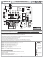 3
3
-
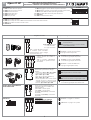 4
4
-
 5
5
-
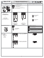 6
6
-
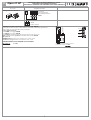 7
7
-
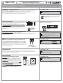 8
8
-
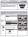 9
9
-
 10
10
-
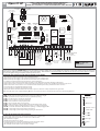 11
11
-
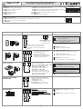 12
12
-
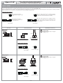 13
13
-
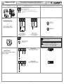 14
14
-
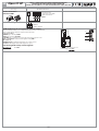 15
15
-
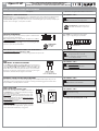 16
16
-
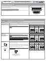 17
17
-
 18
18
-
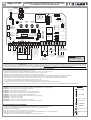 19
19
-
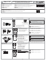 20
20
-
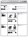 21
21
-
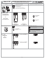 22
22
-
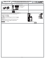 23
23
-
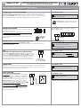 24
24
-
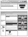 25
25
-
 26
26
-
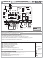 27
27
-
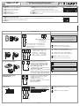 28
28
-
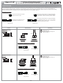 29
29
-
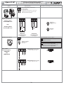 30
30
-
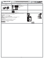 31
31
-
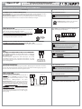 32
32
-
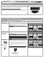 33
33
-
 34
34
-
 35
35
-
 36
36


in altre lingue
- English: Fadini elpro37hp
- français: Fadini elpro37hp
- Deutsch: Fadini elpro37hp
Documenti correlati
-
Fadini elpro37ds Instructions Manual
-
-
-
-
-
-
-
-
-
Altri documenti
-
Meccanica Fadini Elpro 12 EVO Instructions Manual
-
Erone SEP230M2X Manuale del proprietario
-
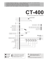 Key Automation 580ISCT-400 Manuale utente
-
CAME BY-3500T Guida d'installazione
-
Key Gates CT-400 Manuale utente
-
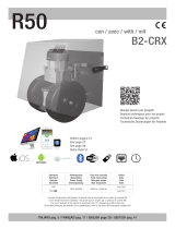 RIB AA21580 Manuale utente
-
CAME All Manuale del proprietario
-
-

