Mitsubishi Electric DX-VS1UE Setup Manual
- Tipo
- Setup Manual

THIS INSTRUCTION MANUAL IS IMPORTANT TO YOU.
PLEASE READ IT BEFORE USING YOUR VIDEO SERVER BOX.
Ver.1.0a
VIDEO SERVER BOX
DX-VS1UE
SETUP GUIDE
ENGLISHOTHERS


DX-VS1UE Setup Guide
2
Intel
®
, Pentium
®
, Celeron
®
are registered trademarks or trademarks the Intel Corporation in the US
and other regions.
Adobe
®
, Adobe Acrobat
®
are registered trademarks or trademarks the Adobe Systems Incorporated
in the US and other regions.
Microsoft
®
, Windows
®
, ActiveX
®
, Internet Explorer are registered trademarks or trademarks the
Microsoft Corporation in the US and other regions.
(The official name of Windows is Microsoft Windows Operating System.)
All other company and product names appearing herein are the property of their respective owners.
Moreover, the “®” mark and the “TM” mark are not described in this document.
* Windows 98SE is an abbreviation of Microsoft Windows 98 Second Edition.
* Windows NT4.0 WS is an abbreviation of Microsoft Windows NT Workstation Version 4.0.
* Windows 2000 is an abbreviation of Microsoft Windows 2000 Professional.
* Windows Me is an abbreviation of Microsoft Windows Millennium Edition.
* Windows XP is an abbreviation of Microsoft Windows XP Home Edition and Microsoft Windows
XP Professional Edition.
Mitsubishi Electric Corporation reserved all rights, including copyright, related to this product.
Never photocopy or reproduce all or a part of this document without prior consent of Mitsubishi
Electric Corporation.
ENGLISH

3
DX-VS1UE Setup Guide
Important safeguards
PLEASE READ ALL THESE INSTRUCTIONS REGARDING YOUR VIDEO SERVER BOX AND RETAIN FOR FUTURE
REFERENCE. FOLLOW ALL WARNINGS AND INSTRUCTIONS MARKED ON THE VIDEO SERVER BOX.
1. Read Instructions
All the safety and operating instructions should be read before the appliance is operated.
2. Retain Instructions
This safety and operating instructions should be retained for future reference.
3. Heed Warnings
All warnings on the appliance and in the operating instructions should be adhered to.
4. Follow Instructions
All operating and use instructions should be followed.
5. Cleaning
Unplug this product from the wall outlet before cleaning. Do not use liquid or aerosol cleaners. For cleaning, wipe the
product with a damp cloth and then wipe up with a dry one.
6. Attachments
Do not use attachments not recommended by the product manufacturer as they may cause hazards.
7. Water and Moisture
Do not use this product near water - for example, near a bath tub, wash bowl, kitchen sink, or laundry tub, in a wet
basement, or near a swimming pool, and the like.
8. Accessories
Do not place the product on an unstable cart, stand, tripod, bracket, or table. The product may fall, causing serious injury.
Any mounting of the appliance should follow the manufacturer's instructions, and should use a mounting accessory
recommended by the manufacturer.
An appliance and cart combination should be moved with care. Quick stops, excessive force, and uneven surfaces may
cause the appliance and cart combination to overturn.
9. Ventilation
Slots of terminals in the cabinet are provided for ventilation and to ensure reliable operation of the product and to protect it
from overheating, and these openings must not be blocked or covered. This product should never be placed near or over
a radiator or heat register. This product should not be placed in a built-in installation such as a bookcase or rack unless
proper ventilation is provided or the manufacturer's instructions have been adhered to.
10. Power Sources
This product should be operated only from the type of power source indicated on the marking label. For products intended
to operate from battery power, other sources, refer to the operating instructions.
11. Grounding or Polarization
This product requires a 3-wire grounding-type plug, a plug having a third (grounding) pin. The power cord supplied for this
product is for use in Europe. When using in the country other than Europe, use the appropriate power cord for your
country. This plug will only fit into a grounding-type power outlet. This is a safety feature. If you are unable to insert the
plug into the outlet, contact your electrician to replace your obsolete outlet. Do not defeat the safety purpose of the
grounding-type plug.
12. Power-Cord Protection
Power-supply cords should be routed so that they are not likely to be walked on or pinched by items placed upon or against
them, paying particular attention to cord at plugs, convenience receptacles, and the point where they exit from the appliance.
13. Lightning
For added protection for this product receiver during a lightning storm, or when it is left unattended and unused for long
periods of time, unplug it from the wall outlet. This will prevent damage to the product due to lightning and power-line
surges.
14. Overloading
Do not overload wall outlets and extension cords as this can result in a risk of fire or electric shock.
15. Object and Liquid Entry
Never fall and insert any object into the product. Never spill liquid of any kind on the product.
16. Servicing
Do not attempt to service this product yourself as opening or removing covers may expose you to dangerous voltage or
other hazards. Refer all servicing to qualified service personnel.
ENGLISH

DX-VS1UE Setup Guide
4
17. Damage Requiring Service
Unplug this product from the wall outlet and refer servicing to qualified service personnel under the following conditions:
(a) When the power-supply cord or plug is damaged.
(b) If liquid has been spilled, or objects have fallen and inserted into the product.
(c) If the product has been exposed to rain or water.
(d) If the product does not operate normally by following the operating instructions. Adjust only those controls that are
covered by the operating instructions as an improper adjustment of other controls may result in damage and will often
require extensive work by a qualified technician to restore the product to its normal operation.
(e) If the product has been dropped or the cabinet has been damaged.
(f) When the product exhibits a distinct change in performance, this indicates a need for service.
18. Replacement Parts
When replacement parts are required, be sure the service technician has used replacement parts specified by the
manufacturer or have the same characteristics as the original part. Unauthorized substitutions may result in fire, electric
shock or other hazards.
19. Safety Check
Upon completion of any service or repairs to this product, ask the service technician to perform safety checks to determine
that the product is in safe operating conditions.
20. Heat
The product should be situated away from heat sources such as radiators, heat registers, stoves, or other products
(including amplifiers) that product heat.
CAUTION
Changes or Modifications not expressly approved by the party responsible for compliance could void the users authority
to operate the equipment.
NOTE
This equipment has been tested and found to comply with the limits for a CLASS B digital device, pursuant to Part 15
of FCC Rules. These limits are designed to provide reasonable protection against harmful interference when the
equipment is operated in a commercial environment. This equipment generates, uses and can radiate radio frequency
energy and, if not installed and used in accordance with the instructions, may cause harmful interference to radio
communications. However, there is no guarantee that interference will not occur in a particular installation. If this
equipment does cause harmful interference to radio or television reception, which can be determined by turning the
equipment off and on, the user is encouraged to try correct the interference by one or more of the following measures:
--Reorient or relocate the receiving antenna.
--Increase the separation between the equipment and receiver.
--Connect the equipment into an outlet on a circuit different from that to which the receiver is connected.
--Consult the dealer or an experienced radio/TV technician for help.
NOTE
THIS CLASS B DIGITAL APPARATUS COMPLIES WITH CANADIAN ICES-003.
CET APPAREIL NUM
É
RIQUE DE LA CLASSE B EST CONFORME
À
LA NORME NMB-003 DU CANADA.
ENGLISH

5
DX-VS1UE Setup Guide
Caution and care English
HEAVY OBJECTS SHOULD NEVER BE PLACED ON THE UNIT(E.G., TV)
POWER SOURCE
This appliance operates from a power source of 12 V DC (direct current) or 24 V AC (alternating current) only.
CONNECTING THE POWER CORD TO THIS APPLIANCE
・
When using the supplied AC adapter or 12-V DC power source:
Make sure to connect the positive (+) connector and the negative (-) connector of the power cord to the +12V terminal and the
GND terminal of this appliance respectively. Do not connect the power cord to the terminal for a 24-V AC power source.
Incorrect connection or connection to a wrong terminal will damage the appliance.
When using the supplied AC adapter, use only rated input and output range that indicated on the bottom of AC adapter,
・
When using a 24-V AC power source:
Connect the power cord to the terminal for 24-V AC power source correctly. Leave the GND terminal unconnected.
NEVER TOUCH OR INSERT ANY OBJECT INSIDE THE UNIT
Touching the inside of the cabinet or inserting foreign objects of any kind not only creates a safety hazard but can also cause
extensive damage.
PROTECT THE POWER CORD
Damage to the power cord may cause fire or shock hazard. If the mains cord is damaged, switch off the mains outlet and
carefully unplug the cord by holding the mains plug.
UNPLUG THE POWER CORD DURING A LONG ABSENCE
Unplug the power cord to turn off the power during a long absence.
PROTECT FROM EXCESSIVE FORCE OR SHOCK
To prevent fire or shock hazard, the appliance need to be protected from excessive force or shock.
MAINTAIN GOOD VENTILATION
Do not obstruct the many ventilation holes on the unit. For maximum ventilation, leave some space around the unit and place
the unit on a hard level surface only, and ensure it is not covered during use. Heavy objects should never be placed on the unit.
WHEN NOT IN USE
When not in use always unplug the power cord.
CABINET CARE
Never use petroleum-based cleaners. Clean with a soft cloth moistened with soap and water and wipe dry. PVC cables or
leads should not be left in contact with the cabinet surface for long periods.
INSTALLATION LOCATION
For excellent performance and lasting reliability install in a location that is:-
1. Well ventilated, out of direct sunlight and away from direct heat.
2. A solid vibration-free surface.
3. Free from high humidity, excessive dust and away from magnetic fields.
4. Please ensure that the ventilation fan located on the unit's back panel is not blocked.
UNSUITABLE LOCATIONS
Placing the unit in the following places might shorten the product life:
・
Extremely cold places, such as refrigerated warehouses and ice houses
・
Places where excessive hydrogen sulfide is likely to be generated, such as hot-springs areas
・
Places or locations with salt air environment
WARNING: TO PREVENT FIRE OR SHOCK HAZARD, DO NOT EXPOSE THIS APPLIANCE TO RAIN OR
MOISTURE. THIS APPLIANCE MUST BE GROUNDED.
CAUTION ON USE IN UK AND IRELAND
Do not use the power cord with the plug provided in this appliance. Use the appropriate AC power code for your country.
This Video Server Box complies with the requirements of the EC Directive 89/336/EEC, "EMC Directive". The requirements
for the susceptibility according to EN 55024 and the requirements for interference according to EN 55022 are observed for
the operation on residential areas, business, light industrial premises and in small scale enterprises, inside as well as outside
of the building. All places of operation are characterized by their connection to the low voltage power supply system (DC 12
V or AC 24 V).
The AC adapter provided this product complies with the requirements of the EC Directive 89/336/EEC, "EMC Directive" and
73/23/EEC, "Low Voltage Directive", as amended by Directive 93/68/EEC. The requirements for the susceptibility according
to EN 55024 and the requirements for interference according to EN 55022 are observed for the operation on residential
areas, business, light industrial premises and in small scale enterprises, inside as well as outside of the building. All places
of operation are characterized by their connection to the public low voltage power supply system. This AC adapter is
manufactured in accordance with EN 60950.
There may be cases when the unit's built-in MOTION DETECTION function does not operate properly due to external
condition or video input signal or other factors.
The user will not be indemnified for problems (e.g., monitoring failure or remote operating failure) that occur with either the
unit or a connected device during operation.
ENGLISH

DX-VS1UE Setup Guide
6
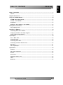
TABLE OF CONTENTS DX-VS1UE
What is DX-VS1UE?............................................................................................................................. 7
Features.............................................................................................................................................................. 7
Supplied Accessories .......................................................................................................................... 8
Using the CD-ROM Manual .............................................................................................................. 10
CD-ROM System Requirements.................................................................................................................... 10
Contents of the CD-ROM .............................................................................................................................. 10
Preparations..................................................................................................................................................... 10
Reading the User’s Manual in the CD-ROM.............................................................................................. 10
Description and Function ................................................................................................................. 11
Using Tapping Screw..................................................................................................................................... 12
Assigning IP Address........................................................................................................................ 13
Connecting DX-VS1UE to Network .............................................................................................................. 13
Configuring IP Address with Setup Program............................................................................................ 14
Viewing Image through Network.................................................................................................................. 16
Input/Output ......................................................................................................................................... 18
How to Make Cable ....................................................................................................................................... 18
Connecting Power .......................................................................................................................................... 19
Connecting Serial Cable................................................................................................................................ 20
Connecting an External Sensor Device...................................................................................................... 20
DIP Switch ....................................................................................................................................................... 21
Video Input/Output ......................................................................................................................................... 21
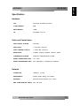
Specification ........................................................................................................................................ 22
Hardware .......................................................................................................................................................... 22
Video and Compression................................................................................................................................ 22
Network ............................................................................................................................................................ 22
Environment..................................................................................................................................................... 23
Additional Function & I/O ............................................................................................................................. 23
Others............................................................................................................................................................... 24
Mechanical ....................................................................................................................................................... 24
ENGLISH

7
DX-VS1UE Setup Guide
OVERVIEW DX-VS1UE
What is DX-VS1UE?
Video Server Box DX-VS1UE offers the solution of the network type remote surveillance server
having many features, such as an internet server, an image compression device, and serial device
control. Viewing image transmitted from a digital recorder or a PTZ(Pan/Tilt/Zoom) camera,
operating those devices can be performed through DX-VS1UE.
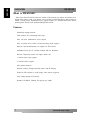
Features
Monitoring through network
Flash memory for customizing home page.
Max. 100 users simultaneous access support
Max. 64 points Preset control (Group and Swing mode support)
RS-232C and RS-485/RS-422 port support for PTZ control
Embedded Linux OS for excellent stability and less downtime
Wavelet compression system for higher refresh rate
1 channel video input support
4 external sensors support
S/W motion detection
Network security through password protect and IP filtering
E-Mail & FTP function to send images when sensors triggered
Easy setting through web browser
Dynamic IP (DHCP, Floating IP) support (for xDSL)
ENGLISH

DX-VS1UE Setup Guide
8
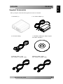
Supplied Accessories
When you unpack, check that all the supplied accessories are included.
1. DX-VS1UE (1) 2. AC Power Adapter (1)
3. AC Power Cord(1) 4. CD-ROM (including the Setup Program
and User’s manual)(1)
5. Ethernet Cable (1, red)
(UTP category 5 crossover cable)
6.Ethernet Cable(1, white)
(UTP category 5 straight cable)
OVERVIEW DX-VS1UE
ENGLISH

9
DX-VS1UE Setup Guide
OVERVIEW DX-VS1UE
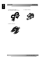
7. RS-232C Serial Cable (1)
(For connecting to digital recorder)
8. Tapping Screws(4)
9. Plastic Anchors (4)
ENGLISH

DX-VS1UE Setup Guide
10
OVERVIEW DX-VS1UE
Using the CD-ROM Manual
The supplied CD-ROM disc includes “DX-VS1UE User’s manual” and various programs for DX-
VS1UE.
CD-ROM System Requirements
CPU : Intel Pentium series or Celeron series 400MHz or faster
Memory(RAM) : 128MB or more
CD-ROM drive : x8 or faster
Monitor : resolution 1024x768 or higher
OS : Windows 98SE/Me/NT4.0SP6/2000/XP SP1
In case these requirements are not satisfied, access to the CD-ROM disc may be impossible.
Contents of the CD-ROM
DX-VS1UESetup.exe : DX-VS1UE Setup Program
ar505enu.exe : Acrobat reader Program
DX-VS1Control installer.exe : ActiveX Program for manual installation
DX-VS1UE User's Guide V1.0.PDF : DX-VS1UE User’s Manual
*There are both “English” and “Japanese” folders in the “Acrobat reader”, “Document” and “Setup” folder
in the attached CD-ROM. Please refer to “English” folder.
Preparations
Adobe Acrobat Reader Version 5.0 must be installed on your computer in order to use the user’s
manual contained in the CD-ROM disc.
<NOTE>
If Adobe Acrobat Reader is not installed on your computer, please use the Acrobat Reader
Setup Program included in the CD-ROM.
Reading the User’s Manual in the CD-ROM
To read the user’s manual contained in the CD-ROM, do the following step.
1. Insert the supplied CD-ROM into your CD-ROM drive.
2. Open the pdf-format user’s manual.
ENGLISH

11
DX-VS1UE Setup Guide
OVERVIEW DX-VS1UE
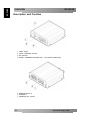
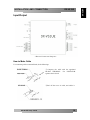
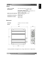
Description and Function
① VIDEO INPUT
② VIDEO THROUGH OUTPUT
③ DIP SWITCH
④ SERIAL COMMUNICATION(RS-232C , RS-232C/RS-422/RS-485)
⑤ SENSOR INPUT x4
⑥ ETHERNET
⑦ POWER(DC12V, AC24V)
ENGLISH

DX-VS1UE Setup Guide
12
OVERVIEW DX-VS1UE
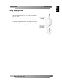
Using Tapping Screw
The following describes how to attach DX-VS1UE to
wall or ceiling.
1) Make a hole. (diameter:Φ6.5, depth:30mm or longer)
2) Insert the supplied PLASTIC ANCHOR into the hole.
3)
Fix DX-VS1UE with the supplied TAPPING SCREW.
ENGLISH

13
DX-VS1UE Setup Guide
INSTALLATION AND CONNECTION DX-VS1UE
Assigning IP Address
To connect DX-VS1UE to network, assign a new IP address to the DX-VS1UE.
Setup Program is used to set IP address.
Do the following step to use the Setup Program contained in the supplied CD-ROM.
To use the Setup Program, DX-VS1UE should be connected to the same local network as client’s
PC.
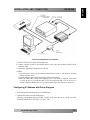
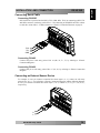
Connecting DX-VS1UE to Network
Connect DX-VS1UE to client’s PC directly with crossover cable, or through HUB with straight
cable. Please refer to the following pictures.
Connecting client’s PC to DX-VS1UE directly
1) Connect DX-VS1UE to Client’s PC with crossover cable.
2) Connect a digital recorder or an external camera to the video input terminal of DX-VS1UE
with BNC cable.
3) Connect the supplied AC Adapter to DX-VS1UE.
ENGLISH

DX-VS1UE Setup Guide
14
INSTALLATION AND CONNECTION DX-VS1UE
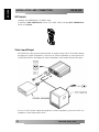
Connecting DX-VS1UE to Local Network
1) Connect DX-VS1UE to a hub with straight cable.
2) Connect a digital recorder or an external camera to the video input terminal of DX-VS1UE
with BNC cable.
3) Connect the supplied AC Adapter to DX-VS1UE.
<NOTE>
1. Note that power cable must be connected after Ethernet cable is connected for avoiding
damage on DX-VS1UE
2. Connect Ethernet cable to the Ethernet plug of DX-VS1UE firmly.
3. Check the LED of DX-VS1UE after supplying power. After power is supplied, yellow LED
is on for the first 4-5 seconds and then it goes off, and green LED is on for the first 1-2
seconds, and then it blinks once at every one second as long as the network is connected.
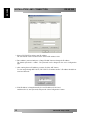
Configuring IP Address with Setup Program
1. Insert the supplied CD-ROM into your CD-ROM drive.
2. Open the file named “DX-VS1UESetup.exe”.
After the setup program starts up, All DX-VS1UEs on the same network as your PC are listed.
Default IP address of DX-VS1UE is "192.168.1.100".
ENGLISH

15
DX-VS1UE Setup Guide
INSTALLATION AND CONNECTION DX-VS1UE
3. Select a DX-VS1UE to assign a new IP Address.
The selected DX-VS1UE is shown in the “Selected IP Address” field.
4. Enter Admin’s password and press “Change IP Addr” button to change the IP address.
The default password is “admin”. The password can be changed on the server configuration
page.
5. After entering the new IP Address you want, click the “OK” button.
To view image through DX-VS1UE, DX-VS1UE’s IP address and PC’s IP address should be at
same local Network.
6. If the IP address is changed normally, the new IP address will be listed.
And then select it, enter password, and press the “Start Configuration” button.
ENGLISH

DX-VS1UE Setup Guide
16
INSTALLATION AND CONNECTION DX-VS1UE
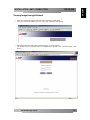
Viewing Image through Network
1. Start up web browser and enter DX-VS1UE’s IP address in URL field.
After you enter the IP address, the User Login page of DX-VS1UE appears.
2. Enter passwords into each password field and press “LOGIN” button.
The default value of each password is not configured (i.e. default value of each password is null
string)
ENGLISH

17
DX-VS1UE Setup Guide
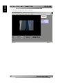
INSTALLATION AND CONNECTION DX-VS1UE
3. You can check image on the simple viewer page.
ENGLISH

DX-VS1UE Setup Guide
18
INSTALLATION AND CONNECTION DX-VS1UE
Input/Output
<Electrical Connection Diagram>
How to Make Cable
For connecting cable to terminal block, do the followings.
① Compress the cable with the appointed
BLADE TERMINAL. Use INSULATOR
against electric shock.
②Peel off the cover of cable, and solder it.
ENGLISH

19
DX-VS1UE Setup Guide
INSTALLATION AND CONNECTION DX-VS1UE
Connecting Power
Before supplying power to DX-VS1UE, note that power cable is connected to DX-VS1UE
properly. Don’t connect power cable to DX-VS1UE with power being supplied.
DC POWER
When connecting DC power, be cautious of “+” / “-“. The pin with tagged “+12” should be
connected to the related hole, and another pin should be connected to “GND” hole. And then fix
them by turning screws clockwise.
AC POWER
Connect two pins(AC24V, AC24V) as followings.
ENGLISH
La pagina si sta caricando...
La pagina si sta caricando...
La pagina si sta caricando...
La pagina si sta caricando...
La pagina si sta caricando...
La pagina si sta caricando...
La pagina si sta caricando...
La pagina si sta caricando...
La pagina si sta caricando...
La pagina si sta caricando...
La pagina si sta caricando...
La pagina si sta caricando...
-
 1
1
-
 2
2
-
 3
3
-
 4
4
-
 5
5
-
 6
6
-
 7
7
-
 8
8
-
 9
9
-
 10
10
-
 11
11
-
 12
12
-
 13
13
-
 14
14
-
 15
15
-
 16
16
-
 17
17
-
 18
18
-
 19
19
-
 20
20
-
 21
21
-
 22
22
-
 23
23
-
 24
24
-
 25
25
-
 26
26
-
 27
27
-
 28
28
-
 29
29
-
 30
30
-
 31
31
-
 32
32


Mitsubishi Electric DX-VS1UE Setup Manual
- Tipo
- Setup Manual
in altre lingue
- English: Mitsubishi Electric DX-VS1UE
- français: Mitsubishi Electric DX-VS1UE
- español: Mitsubishi Electric DX-VS1UE
- Deutsch: Mitsubishi Electric DX-VS1UE
- Nederlands: Mitsubishi Electric DX-VS1UE
Altri documenti
-
Denon DBP-2012UD Manuale del proprietario
-
JVC VN-T216VPRU Manuale utente
-
Yamaha RX V3900 - AV Network Receiver Manuale utente
-
Yamaha RX-V3800 Manuale del proprietario
-
Yamaha DSP-Z11 Manuale utente
-
Yamaha DSP-Z7 Manuale del proprietario
-
Yamaha RX-A810 Manuale del proprietario
-
Yamaha RX-A1010 Manuale del proprietario
-
Yamaha RX-V1071 Manuale del proprietario
-
TOA WD-5800 Manuale utente