
IT Istruzioni per installazione
EN Installation manual
FR Instructions pour l’installation
DE Installationsanweisung
ES Instrucciones para instalación
EW2 SERIES
INDUSTRIAL PANEL PC

1
E
W
2
1
2
A
2
E
W
2
1
2
B
3
E
W
2
1
2

4
E
W
2
1
5
A
5
E
W
2
1
5
B
6
E
W
2
1
5

7
E
W
2
1
8
A
8
E
W
2
1
8
B
9
E
W
2
1
8

1
0
E
W
2
2
2
A
1
1
E
W
2
2
2
B
1
2
E
W
2
2
2

1
3
E
W
2
.
.
A
1 2
1
4
E
W
2
.
.
A
2
3
1
FRONT
BACK
1
5
E
W
2
1

1
6
E
W
2
CB
EA
D
1
7
E
W
2
F
1
8
E
W
2
PUSH
PUSH
PUSH
PULL
CFAST
HDD/SSD

1
9
E
W
2
2
0
E
W
2
2
1
E
W
2

2
2
E
W
2
2
3
E
W
2
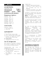
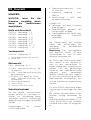
Power supply 4 pins connectors
1 +24 VDC
2 0 VDC
3 Not Connected
4 Protective ground
2
4
E
W
2
~
+-
24V
3
+24V
PE
0V
EW2xx
DEVICE
PE
N
L1
4
1
2

2
5
E
W
2
~
+-
24V
PE
N
L1
~
-
24V
+
PE
N
L1
2
6
E
W
2
2
7
E
W
2
DEVIC
E
EW
2
CONNECTOR
D-SUB
9 PIN FEMALE
470 ohm
1/4 W
GND
DATA-
DATA+
220 ohm
1/4 W
470 ohm
1/4 W
120 ohm
1/4 W
1DATA+
DATA-2
+5VDC

2
8
E
W
2
DEVIC
E
EW
2
CONNECTOR
D-SUB
9 PIN FEMALE
470 ohm
1/4 W
GND
DATA-
DATA+
220 ohm
1/4 W
470 ohm
1/4 W
120 ohm
1/4 W
1DATA+
+5VDC
GND5
DATA-2
6,8V
600W
6,8V
600W

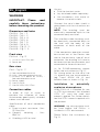
IT_Italiano
AVVERTENZA
IMPORTANTE: leggere
attentamente queste
istruzioni prima della
installazione del prodotto.
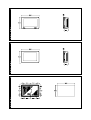
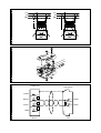
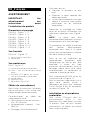
Dimensioni e forature
EW212A – Fig. 1 . 3
EW212B – Fig. 2 . 3
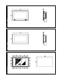
EW215A – Fig. 4 . 6
EW215B – Fig. 5 . 6
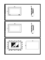
EW218A – Fig. 7 . 9
EW218B – Fig. 8 . 9
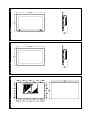
EW222A – Fig. 10 . 12
EW222B – Fig. 11 . 12
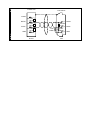
Vista frontale
EW2xxA – Fig. 13
1) Porta seriale USB.
2) Power led.
Vista posteriore
EW2 – Fig. 16 . 17
A) Vedi manuale scheda madre.
B) COM - Vedi manuale scheda madre.
C) POWER (ATX power on switch) -
Vedi manuale scheda madre.
D) Alimentazione.
E) Slot PCI/PCIe.
F) Alloggiamento HDD/SSD/Cfast.
Cavi di collegamento
Per limitare al massimo l’influenza
dei disturbi è necessario utilizzare
cavi schermati di buona qualità.
Caratteristiche del cavo di
collegamento seriale:
! Resistenza in corrente continua -
Max. 151 Ohm/Km
! Accoppiamento capacitivo -
Max. 29pF/m
! Schermatura > 80% oppure
Totale
In ogni caso:
! Cercare il percorso più breve.
! Effettuare la posa separata da
cavi disturbati e/o cavi di
potenza.
! Utilizzare connettori con gusci
metallici o di plastica conduttiva.
Collegare la schermatura del cavo
seriale attenendosi alle indicazioni
riportate in Fig. 26.
NOTA: La calza deve risultare
connessa elettricamente sia al
corpo connettore che al coperchio.
Lo schermo del cavo deve risultare
connesso elettricamente sia alla
custodia che al corpo del
connettore stesso da ambo i lati del
cavo.
Nel caso che non possa essere
eseguita l'operazione di
collegamento schermo lato
Dispositivo causa tipo di
connettore seriale particolare, la
schermatura stessa dovrà essere
portata esternamente al connettore
e collegata al morsetto di terra.
Per la connessione in RS485
seguire le indicazioni riportate in
Fig. 27.
In presenza di forti disturbi sulla
linea seriale utilizzare due
soppressori di disturbi (e.s. Transil
6,8V 600W) e collegarli come in
Fig. 28.
Installazione in atmosfera
potenzialmente esplosiva
Per l’utilizzo del EW2xxA in
ambiente ATEX occorre applicare
l’apposito KIT in dotazione al
prodotto. Per ulteriori dettagli vedi
apposito manuale a corredo del
prodotto.

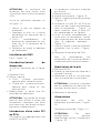
ATTENZIONE: la piastrina di
chiusura DEVE essere montata
PRIMA dell’installazione in ambiente
ATEX.
Attenersi alle indicazioni riportate
in Fig. 14.
1. Rimuovere la guarnizione dal
supporto di protezione
2. Applicare la guarnizione sulla
parte posteriore della piastrina
di chiusura USB.
3. Aprire completamente il tappo
di gomma e applicare con le
apposite viti la piastrina di
chiusura USB.
4. Richiudere il tappo di gomma.
Installazione EW2
EW2 – Fig. 15
Inserimento/rimozione HDD
e Cfast
Attenersi alle indicazioni riportate
in Fig. 18.
a. Spegnere il EW2.
b. Rimuovere lo sportello e riporlo su
un piano.
! Cfast: sistema push-push;
premere per inserirla e premere
per estrarla.
! HDD: sistema push-pull; premere
per inserirlo e tirare per estrarlo.
c. Una volta terminate le operazioni
riposizionare lo sportello come in
origine.
ATTENZIONE: Durante l’estrazione
l’HDD potrebbe opporre una certa
resistenza dovuta alle connessioni
elettriche. Applicare una forza
costante (non eccessiva) per
consentirne lo sgancio dai
connettori.
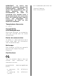
Inserimento di una scheda
PCI o PCIe
EW2 prevede l’alloggiamento per
una scheda PCI o PCIe.
La massima dimensione consentita
è 180mm.
a. Spegnere il EW2.
b. Rimuovere la copertura - Fig. 19.
c. Rimuovere la staffetta di chiusura -
Fig. 20.
d. Inserire la scheda PCI o PCIe
avendo cura di inserirla
perfettamente nel connettore - Fig.
21 (nelle figure viene mostrata per
semplicità solo la scheda PCI).
e. Prima di inserire completamente la
scheda nel connettore verificare
che la staffetta sia entrata
nell’apposita sede - Fig. 22.
f. Fissare la scheda una volta che è
stata perfettamente inserita - Fig.
22.
g. Rimontare la copertura del EW2.
Per il collegamento ai connettori
della scheda fare riferimento alla
documentazione del costruttore.
Sostituzione della batteria
a. Spegnere il EW2.
b. Rimuovere la copertura (lato
marchio esaware).
c. Sostituire la batteria della scheda
madre (vedi manuale scheda
madre).
ATTENZIONE: Inserire la batteria
nuova rispettando il tipo e le
polarità.
d. Rimontare la copertura.
Alimentazione
Significato dei pin del connettore di
alimentazione - Fig. 23.
Collegamento consigliato - Fig. 24.

ATTENZIONE: queste due
configurazioni danneggiano
gravemente il EW2 - Fig. 25.
IMPORTANTE: La massa dei
dispositivi collegati alle porte di
comunicazione seriali e/o
parallele deve essere
tassativamente allo stesso
potenziale dello 0V di
alimentazione del EW2. La
circolazione di una corrente tra lo
0V di alimentazione e la massa
delle porte di comunicazione
potrebbe causare il
danneggiamento di alcuni
componenti del EW2 o dei
dispositivi ad esso collegati.
Temperatura di esercizio
0 / +50°C
Compatibilità
elettromagnetica
Restrizioni d’uso: i requisiti di
protezione non sono assicurati in
zone residenziali.
Porte di comunicazione
Per il collegamento ai connettori
delle periferiche fare riferimento
alla documentazione della scheda
madre.
Pulizia della superficie
Per la pulizia del EW2 si consiglia di
utilizzare Alcool Etilico Denaturato.
Certificazioni
Tutti i prodotti descritti in questo
manuale sono conformi ai seguenti
standard:
compatibilità elettromagnetica
(EMC):
! emissioni EN 61000-6-4
(2007)
! immunità EN 61000-6-2
(2005)
e perciò rispondono a:
Council Directive
EMC 2004/108/EC

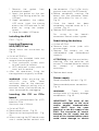
EN_English
WARNING
IMPORTANT: Please read
carefully these instructions
before mounting the product.
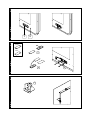
Dimensions and holes
EW212A – Fig. 1 . 3
EW212B – Fig. 2 . 3
EW215A – Fig. 4 . 6
EW215B – Fig. 5 . 6
EW218A – Fig. 7 . 9
EW218B – Fig. 8 . 9
EW222A – Fig. 10 . 12
EW222B – Fig. 11 . 12
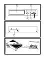
Front view
EW2xxA – Fig. 13
1) Universal Serial Bus port.
2) Power led.
Rear view
EW2 – Fig. 16 . 17
A) See motherboard manual.
B) COM - See motherboard manual.
C) POWER (ATX power on switch) -
See motherboard manual.
D) Power supply.
E) Slot PCI/PCIe.
F) Slot for HDD/SSD/CFast.
Connection cables
In order to limit as much as
possible the influence of these
disturbances good quality shielded
cables must be used.
Specifications of serial connection
cable:
! Direct current resistance - Max.
151 Ohm/Km
! Capacity coupling - Max.
29pF/m
! Shielding > 80% or total
Always:
! Find the shortest route.
! Lay disturbed cables separately.
! Use connectors with metal or
conduc-tive plastic shells.
Connect the serial cable shield in
accordance with the instructions on
Fig. 26.
NOTE: The braiding must be
electrically connected both to the
connector body and shell.
The interface cable braiding must
be electrically connected both to
the shell and the body of the
connector at both ends of the
cable.
If the connection operation cannot
be carried out at the Device side
due to the particular type of serial
connector, the braiding will have to
be taken outside the connector and
connected to the earth terminal.
As for RS485-connection, please
follow the instructions by Fig. 27.
For strong spikes on the serial line
it’s, please use two noise-reducers
(eg Transil 600W 6.8 V) and
connect them as shown in Fig . 28.
Installation in potentially
explosive atmospheres
When EW2xxA is intended for use
in ATEX environment, the attached
ATEX KIT must be used and
properly applied. For further details
see the ATEX manual supplied with
the product.
WARNING: the closing plate must
be fixed before the EW2xx is
installed in ATEX environment.
Please follow the instructions by
Fig. 14.

1. Remove the gasket from
protective support.
2. Apply the gasket on the rear
side of the closing plate for the
USB port.
3. Open completely the rubber
USB cover, insert the closing
plate in the USB hole and fix the
plate by using the proper
screws.
4. Close the rubber USB cover
Installing the EW2
EW2 – Fig. 15
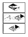
Inserting/Removing
HDD/SSD/CFast
Please follow the instructions by
Fig. 18.
a. Switch off EW2xx.
b. Unscrew the threaded knob and
remove the closing plate.
! Cfast: push-push system, push
to insert, push to remove.
! HDD: push-pull system, push to
insert, pull to remove.
c. After the operations, fixing the
closing plate as originally installed.
WARNING: When extracting the
HDD/SSD may offer some
resistance due to the electrical
connector. Keep on pulling with a
constant force (Not excessive) to
allow the connector unplugging.
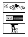
Inserting the PCI or PCIe
board
EW2 has a compartment for a PCI
board or PCIe.
Maximum size is 180mm.
a. Switch off EW2.
b. Remove back cover - Fig. 19.
c. Remove the locking brackets - Fig.
20.
d. When inserting the PCI board make
sure it makes perfect contact with
the connector - Fig. 21 (For clarity
pictures show only the PCI board).
e. Before completely inserting the
board into the connector check
that the bracket fits into its slot -
Fig. 22.
f. Once the board has been
completely inserted screw to fix it
in place - Fig. 22.
g. Replace EW2 back cover.
For wiring to the board’s
connectors consult maker’s guide.
Substituting the battery
a. Switch off EW2.
b. Remove back cover (side with
esaware logo).
c. Replace the battery on the
motherboard (see motherboard
manual).
ATTENTION: Insert the new battery
checking that the polarities are
correct. Discarded batteries should
be placed in appropriate
containers.
d. Replace back cover.
Power supply
Power connector pin-out - Fig. 23.
Recommended power connection -
Fig. 24.
WARNING: These two
configuration will seriously damage
components - Fig. 25.
IMPORTANT: The earth of the
devices connected to the serial
and/or parallel communication
ports MUST have the same
potential as the 0V supply of the
EW2. The circulation of current
between the 0V supply and the
earth of the communication ports
could cause damage to certain

components of the EW2 or of the
devices connected to it.
Working temperature
0 / +50°C
Electromagnetic
compatibility
Restriction of use: protection
requirements are not ensured in
residential areas.
Communication ports
Refer to motherboard
documentation for connection of
link to peripheral devices.
Cleaning
For cleaning the EW2 we
recommend Denaturalised Ethyl
Alcohol.
Certifications
All the products described in this
manual comply with the following
standards:
electromagnetic compatibility
(EMC):
! emissions EN 61000-6-4
(2007)
! immunity EN 61000-6-2
(2005)
and thus are in line with:
Council Directive
EMC 2004/108/EC

FR_Français
AVERTISSEMENT
IMPORTANT : lire
attentivement ces
instructions avant
l’installation du produit.
Dimensions et perçage
EW212A – Figure . 1 . 3
EW212B – Figure . 2 . 3
EW215A – Figure . 4 . 6
EW215B – Figure . 5 . 6
EW218A – Figure . 7 . 9
EW218B – Figure . 8 . 9
EW222A – Figure . 10 . 12
EW222B – Figure . 11 . 12
Vue frontale
EW2xxA – Figure . 13
1) Port Universal Serial Bus.
2) Power led.
Vue postérieure
EW2 – Fig. 16 . 17
A) Voir le manuel de la carte mère
B) COM - Voir le manuel de la carte
mère.
C) POWER (ATX power on switch) -
Voir le manuel de la carte mère.
D) Alimentation.
E) Baie PCI/PCIe.
F) Baie HDD/SSD/CFast.
Câbles de raccordement
Pour limiter au maximum l’influence
de ces parasites il faut utiliser des
câbles blindés de bonne qualité.
Caractéristiques du câble de
raccordement sériel :
! Résistance en courant continu -
Max. 151 Ohm/Km
! Accouplement capacitif - Max.
29pF/m
! Blindage > 80% ou bien total
Dans tous les cas :
! Chercher le parcours le plus
bref.
! Effectuer la pose séparée des
câbles perturbés.
! Utiliser des connecteurs du type
spécial à carcasse avec gaines
métalliques ou en plastique
conductible.
Raccorder le blindage du câble
sériel en se tenant strictement aux
indications reportées dans Figure .
26.
NOTE : La gaine doit être
connectée électriquement au corps
du connecteur et à son habillage.
La protection du câble d’interface
doit résulter électriquement
connectée aussi bien à la gaine
qu’au corps du connecteur luimême
des deux côtés du câble.
Dans le cas où l’opération de
raccordement protection côté
Périphérique ne puisse pas être
exécutée à cause du type
particulier de connecteur sériel, le
blindage même devra être porté
extérieurement au connecteur et
raccordé à la borne de terre.
Pour la connexion RS485, suivez les
instructions de la Figure . 27.
Pour les pointes importantes sur la
ligne série, veuillez utiliser 2
réducteurs de bruit (par exemple
Transil 600W 6.8V) et connectez
les selon la Figure . 28.
Installation en atmosphères
explosibles
Pour utiliser l’EW2xxA dans un
environnement ATEX il faut
appliquer le kit spécifique livré avec
la produit. Pour de plus amples
informations, se référer au manuel
fourni avec le produit.

ATTENTION : le couvercle de
fermeture doit être monté avant
l’installation dans un environnement
ATEX
Suivre les indications données sur
la Figure . 14.
1. Retirer le joint du support de
protection
2. Appliquer le joint sur la partie
postérieure du couvercle de la
porte USB.
3. Ouvrir complètement le
bouchon en caoutchouc et fixer
avec les vis le couvercle de la
porte USB.
4. Remettre en place le bouchon
en caoutchouc.
Installation du EW2
EW2 – Figure . 15
Introduction/retrait du
disque dur
Suivre les indications de la Figure.
18.
a. Eteindre l’EW2.
b. Retirer la porte.
! Cfast : système push-push ;
appuyer pour insérer et retirer.
! Disque dur : système push-pull ;
appuyer pour insérer et tirer
pour extraire.
c. Repositionner la porte une fois
terminées les opérations.
ATTENTION : l’extraction du disque
pourrait être difficile à cause des
connections. Appliquer une force
constante mais non excessive pour
permettre la déconnexion.
Introduction d’une carte PCI
ou PCIe
EW2 prévoit un logement pour une
carte PCI ou PCIe.
La dimension maximum autorisée
est 180mm.
a. Éteindre le EW2.
b. Enlever le couvercle – Figure . 19.
c. Retirer la petite patte de fermeture
- Figure . 20.
d. Introduire la carte PCI ou PCIe en
ayant soin de l’insérer correctement
dans le connecteur – Figure . 21
(pour simplifier, seule la carte PCI
est représentée sur les figures).
e. Avant d’insérer complètement la
carte dans le connecteur, vérifier
que la petite patte soit bien entrée
dans le logement approprié –
Figure . 22.
f. Une fois qu’elle a été parfaitement
introduite, fixer la carte – Figure .
22.
g. Remonter le couvercle de EW2.
Pour le raccordement aux
connecteurs de la carte se référer à
la documentation du constructeur.
Substitution de la pile
a. Éteindre le EW2.
b. Enlever le couvercle (du côté de la
marque Esaware).
c. Remplacer la pile sur la carte mère
(voir le manuel de la carte mère).
ATTENTION : Introduire la nouvelle
pile en respectant les polarités. Ne
pas jeter les piles dans la nature.
d. Remonter le couvercle.
Alimentation
Signification des pins du
connecteur d’alimentation - Figure .
23.
Connexion conseillée - Figure . 24.
ATTENTION : Ces deux
configurations peuvent
endommager certains composants
- Figure . 25.

IMPORTANT : La masse des
dispositifs connectés aux ports de
communication parallèles ou
sériels doit formellement être au
même potentiel qu’il 0V
d’alimentation du EW2. La
circulation d’un courant entre il
0V d’alimentation et la masse des
ports de communication pouvait
causer des dommages aux
composants du EW2 ou des
dispositifs connectés.
Température d’exercice
0 / +50°C
Compatibilité
électromagnétique
Restriction d'emploi: les protection
n'est pas assurée dans les zones
résidentielles.
Portes de comunication
Se référer à la documentation de la
carte mère pour les connexions
avec les périphériques.
Nettoyage
Pour nettoyer le EW2 est conseillé
d’utiliser de l’Alcool Éthylique
Dénaturé.
Certifications
Tous les produits décrits dans ce
manuel sont conformes aux
standards suivants :
compatibilité electromagnétique
(EMC) :
! émissions EN 61000-6-4
(2007)
! immunité EN 61000-6-2
(2005)
et ils répondent pour cela aux :
Council Directive
EMC 2004/108/EC
La pagina si sta caricando...
La pagina si sta caricando...
La pagina si sta caricando...
La pagina si sta caricando...
La pagina si sta caricando...
La pagina si sta caricando...
La pagina si sta caricando...
La pagina si sta caricando...
-
 1
1
-
 2
2
-
 3
3
-
 4
4
-
 5
5
-
 6
6
-
 7
7
-
 8
8
-
 9
9
-
 10
10
-
 11
11
-
 12
12
-
 13
13
-
 14
14
-
 15
15
-
 16
16
-
 17
17
-
 18
18
-
 19
19
-
 20
20
-
 21
21
-
 22
22
-
 23
23
-
 24
24
-
 25
25
-
 26
26
-
 27
27
-
 28
28


ESA EW222A Guida d'installazione
- Tipo
- Guida d'installazione
in altre lingue
- English: ESA EW222A Installation guide
- français: ESA EW222A Guide d'installation
- español: ESA EW222A Guía de instalación
- Deutsch: ESA EW222A Installationsanleitung
Altri documenti
-
Eldes EW2 Guida utente
-
-
Yamaha RY8 Manuale utente
-
Samsung WF-B1261 Manuale utente
-
ASROCK K10N780SLIX3 Manuale del proprietario
-
ASROCK AOD790GX-128M Manuale del proprietario
-
-
ASROCK K10N7SLI Manuale del proprietario
-
ASROCK K10N750SLI-WIFI Manuale del proprietario
-
Sulzer Muffin Monster™ – 30004T Installation, Operating And Maintenance Instructions