
EN
V2.2 Supplemental Manual

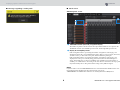
CONTENTS
2 RIVAGE PM series V2.2 Supplemental Manual
Supporting a new HY144-D-SRC card .............................................................3
Supporting a new HY128-MD card .................................................................4
MIX SEND COPY ..............................................................................................6
Additional option during loading....................................................................7
Displaying a patch conflict between DSP engines..........................................8
Expanded SENDS ON FADER mode function ................................................10
Additional CUE monitor sources....................................................................10
Mirroring Operation Check function.............................................................11
Contents

CONTENTS
Supporting a new HY144-D-SRC card
3 RIVAGE PM series V2.2 Supplemental Manual
This new digital I/O card supports four options for SRC (Sampling Rate Converter) mode, as well as
the Dante digital audio network. It can handle 144 channels and be installed in the HY card slot.
■ About SRC mode
Five SRC mode options are provided. You can switch to each mode option by writing firmware that
supports the desired mode on the HY144-D-SRC.
*1 Synchronous SRC:
If the clock of the Dante network, and that of the device with the HY144-D-SRC
card installed, are synchronized at a clock ratio of 1:2 (48 kHz
96 kHz or 44.1 kHz
88.2 kHz),
then
data at various sampling frequencies can be transmitted without sacrificing input or output
channels. If the Dante network is operating at 44.1 kHz, the frequency response above 18 kHz
will slightly deteriorate due to the elimination of aliasing.
*2 Asynchronous SRC: In this case, the clock of the Dante network and that of the device with the
HY144-D-SRC card installed do not have to synchronize with each other. You can specify
sampling frequencies separately.
NOTE
• If you are using Synchronous (144io Sync SRC) mode:
If you assign this card in a device on the Dante network as the clock master, the card will operate at
twice the clock value at which it was originally synchronizing to the network.
Example: If this card was operating as a Slave on the 48 kHz Dante network, it will now operate at a
clock of 96 kHz which is generated based on the PTP master clock on the Dante network.
If you plan to set the clock master to Internal or TWINLANe SLAVE on the device that has this card
installed, use Dante Controller to check the “Enable Sync to External” option for this card, and
operate the card as the master on the Dante network.
• You cannot specify a card operating in Asynchronous SRC mode as the clock master. Specify a
different device as the word clock master.
To change the SRC mode, you must rewrite the firmware by using Dante Firmware Update Manager.
For more information, please refer to the “HY144-D-SRC Firmware Update Guide”.
The procedure to mount a card and configure it for Dante audio network can be used with any
HY144-D card.
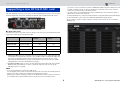
Supporting a new HY144-D-SRC card
Mode name SRC Number of input
channels
Number of output
channels
144io None 144 144
144io Sync SRC Synchronous SRC
*1
144 144
72io Async SRC Asynchronous SRC
*2
72 72
144i Async SRC Asynchronous SRC
*2
144 0
144o Async SRC Asynchronous SRC
*2
0144

CONTENTS
Supporting a new HY128-MD card
4 RIVAGE PM series V2.2 Supplemental Manual
This audio interface card transmits and receives up to 128-in/128-out MADI signals. This card
features two sets of fiber optic and coaxial connectors, supporting redundant connection.
You can use it by inserting it into the HY slot on a DSP engine or I/O rack.
(DSP-R10: HY Slot 3/4, CSD-R7: HY Slot 2/3, RPio622/222: HY Slot 2) Same as Dante cards.
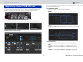
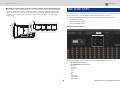
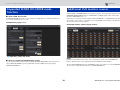
SYSTEM CONFIG popup window
The screen is displayed when the HY128-MD card is inserted into HY SLOT 3 on a DSP engine. The
screen contains the following items:
REDUNDANCY MODE
Enables you to select one of two redundancy combinations.
•MODE 1
Redundancy is maintained by using both optical and coaxial connections.
•MODE 2
Redundancy is maintained by using either two sets of optical or two sets of coaxial
connections.
INPUT PRIORITY
Enables you to specify the input signal that has priority in a redundant pair.
•PRI1
If MODE 1 is selected, signals at OPTICAL 1 and OPTICAL 2 have priority.
If MODE 2 is selected, signals at OPTICAL 1 and COAXIAL 1 have priority.
•PRI2
If MODE 1 is selected, signals at COAXIAL 1 and COAXIAL 2 have priority.
If MODE 2 is selected, signals at OPTICAL 2 and COAXIAL 2 have priority.
Supporting a new HY128-MD card

CONTENTS
Supporting a new HY128-MD card
5 RIVAGE PM series V2.2 Supplemental Manual
SPLIT button
Specifies whether or not the input signal should be split and sent to the output connectors. The
signal will be sent to the same type of output connectors.
•ON
The input signal is split and sent to the output connectors.
•OFF
The input signal from the mounted card is output without being split.
INPUT SRC button
Turns the SRC for MADI input signals on or off.
SRC CLOCK buttons
Enable you to select the input signal clock when the SRC is turned on.
• MADI IN
Selects the MADI IN clock as the SRC’s input clock.
•WCLK IN
Selects the WCLK IN FOR SRC clock as the SRC’s input clock.
Fs indicators
Show whether the input signal is 48 kHz or 44.1 kHz. If a valid MADI signal is not being
input, neither indicator will light up.
RATE buttons
Enable you to select whether the MADI input signal will be processed as 1Fs, 2Fs, or 4Fs.
•1Fs
44.1 kHz/48 kHz, up to 64 channels
•2Fs
88.2 kHz/96 kHz, up to 32 channels
•4Fs
176.4 kHz/192 kHz, up to 16 channels
FRAME indicators
Show the input signal’s frame format. If a valid MADI signal is not being input, neither
indicator will light up.
CHANNEL FORMAT indicators
Show the channel format of the input signal. If a valid MADI signal is not being input, neither
indicator will light up.
OUTPUT SRC button
Turns the SRC for MADI output signals on or off.
SRC CLOCK buttons
Enable you to select the output signal clock while the SRC is turned on.
• MADI IN
The output signal will use the clock that is being input at the corresponding MADI IN
connector.
•WCLK IN
The output signal will use the clock that is being input at the WCLK IN FOR SRC connector.
OUTPUT FRAME buttons
Enable you to select the output signal’s frame format.
•SAME AS INPUT
The same format as the MADI IN signal will be used for the output signal. If a valid MADI
signal is not being input, the signal of the 48 k frame format will be output.
• 96k
The signal of the 96 k frame format will be output.
• 48k
The signal of the 48 k frame format will be output.
OUTPUT CHANNEL FORMAT buttons
Enable you to select the output signal’s channel format.
•SAME AS INPUT
The number of the output signal will be the same as that of the MADI IN signal. If a valid
MADI signal is not being input, the 64-channel signal will be output.
•64
The 64-channel signal will be output.
•56
The 56-channel signal will be output.

CONTENTS
MIX SEND COPY
6 RIVAGE PM series V2.2 Supplemental Manual
■ About the SOFT CTRL (software control) switches on the HY128-MD card
If the switch 1 is set to ON (default setting), you can use the control surface to view and modify the
parameter settings. If the switch 1 is OFF, the parameter settings will be fixed by the DIP switch
settings on the card. For more information, please refer to the “HY128-MD Owner’s Manual.” The
parameters on screen will be grayed out and you will be unable to modify the settings from the
control surface.
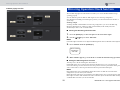
If you are planning to copy the mix parameters for the output channel, the new Simple Copy Sends
function enables you to copy the SENDS parameters for that channel as an option.
You can use the MIX SEND COPY function between the following channel combinations.
• Between MIX channels
• Between MATRIX channels
• Between STEREO channels
CH COPY popup window
The following SENDS parameters will be copied if the WITH SENDS button is turned on.
• If a MIX channel is selected:
• If a MATRIX channel is selected:
Pre/Post
Pre Point
Post Point
Level
Pan
On
Follow On
Follow Fader
Follow DCA
MIX SEND COPY

CONTENTS
Additional option during loading
7 RIVAGE PM series V2.2 Supplemental Manual
• If a STEREO channel is selected:
To Stereo A
To Stereo B
NOTE
The WITH SENDS button will be grayed out and disabled under the following conditions:
• The copy source or paste destination is a surround bus, downmix bus, or mix minus bus.
• The copy source and paste destination use a different type of bus (VARI/FIX).
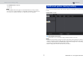
Now you can select whether the Dante audio network settings are loaded while a project file is being
loaded.
LOAD SELECT screen
WITH DANTE SETUP button
Turn this button on to use the Dante settings included in the file to be loaded.
NOTE
• The Dante Controller ID will not change even after the Dante audio network settings are loaded. For
example, if the ID was changed to ID#1 from another number, the Dante settings of the entire system
would be reconfigured based on the DANTE SETUP popup window settings on the corresponding
control surface. To avoid this situation, the ID will not change.
• All Dante settings will be saved in a file without any save options.
Additional option during loading

CONTENTS
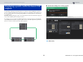
Displaying a patch conflict between DSP engines
8 RIVAGE PM series V2.2 Supplemental Manual
Assuming that a DSP engine is already patched to an output port on the TWINLANe network, if
you try to patch another DSP engine to that same output port, a confirmation dialog will appear on
the control surface that you are operating, asking whether you want the patch to be “stolen” by the
second DSP engine.
Meanwhile, a message will appear on the control surface that was disconnected from the output port
to let you know that the patch was changed (“stolen”).
For example, if you try to patch from multiple DSP engines to the same output port of an I/O rack
on the TWINLANe network, the output port will be “stolen” by the DSP engine that is patched last.
In this case, the above-mentioned messages will be displayed.
■ Confirmation dialog when stealing a patch
This dialog appears only when the STEAL button on the PREFERENCES popup screen is turned on.
STEAL button
Displaying a patch conflict between DSP
engines

CONTENTS
Displaying a patch conflict between DSP engines
9 RIVAGE PM series V2.2 Supplemental Manual
■ Message regarding a stolen patch ■ Patch screen
OUTPUT patch screen
TWINLANe network (main/sub) assignment display
The number of patches is shown in red for the output channels that are not assigned to the
TWINLANe network. (The left half represents main, and the right half represents sub.)
Display for incomplete patches
If the rectangular indicator representing the number of assignments of the target port is
displayed in yellow, the port is available but the patch to that port is not yet active (Not Active).
To make it active, you must remove the patch, and then make the patch again.
If the rectangular indicator representing the number of assignments of the target port is
displayed in red, the port is currently being patched (Used) from another DSP engine or
device. Alternatively, the port may be unavailable (Not Available) because the number of
available ports is limited due to the setting on the card. Please be aware that removing a patch
may inadvertently remove other patches that are being used by different engines.
NOTE
If a patch conflict occurs, the PORT IDENTIFY function of the I/O rack will be disabled. In this case,
the following message will appear in yellow at the bottom of the screen.
“PORT IDENTIFY not available! This channel is not currently patched to an Output Port.”

CONTENTS
Expanded SENDS ON FADER mode function
10 RIVAGE PM series V2.2 Supplemental Manual
■ About SEND SEL-CUE link
In SENDS ON FADER mode, the cue was switched accordingly when you switched the master bus.
You can now turn this function on or off.
PREFERENCES popup screen
[SEND SEL].>[CUE] LINK button
■ About the SENDS ON FADER popup window
You can now adjust the send levels without opening the SENDS ON FADER popup window, if you
engage SENDS ON FADER by pressing and holding down the [SHIFT] key and pressing the
[SENDS ON FADER] key.
CUE A, CUE B, and TALKBACK2 have been added as monitor sources that can be assigned to the
MONITOR SOURCE DEFINE buttons. (TALKBACK2 is a talkback signal on the control surface
that has its CONSOLE ID set to “2”.)
In this way, you can mix and monitor CUE A, CUE B, TALKBACK 1, or TALKBACK 2 along with
other monitor sources. This is convenient if you are using an IEM or back-talk mic (communication
mic from the performer to the engineer).
MONITOR SOURCE SELECT popup window
NOTE
If CUE is selected as the monitor source, we recommend that you turn off the CUE INTERRUPT
button so that the monitor source signal will not be interrupted by the CUE operation.
The new CUE INTERRUPT button for the PHONES settings now enables you to turn INTERRUPT
off. You can also assign this button function to a USER DEFINED key.
Expanded SENDS ON FADER mode
function
Additional CUE monitor sources

CONTENTS
Mirroring Operation Check function
11 RIVAGE PM series V2.2 Supplemental Manual
PHONES popup window
The new Mirroring Operation Check function enables you to check whether DSP mirroring is
operating properly.
You can check the operation while two DSP engines are in a mirroring configuration.
Since this function virtually pauses DSP engine operation, you can use the function at the time of
system setup.
Checking example
Assuming that DSP A and DSP B are in a mirroring configuration, you can use the Mirroring
Operation Check function on DSP A to make sure that DSP B (in the standby state) will
automatically be able to take over if DSP A fails.
■ Starting the Mirroring Check function
1. Press the [MENU] key on the front panel of the active DSP engine.
2. Use the []/[] keys to select “Mirr Chk”.
NOTE
If the DSP engine’s Unit ID does not support the Mirroring Check function, “Mirr Chk” will not appear.
3. Press and hold down the [ENTER] key.
4. When “DONE” appears, you can check to confirm the DSP mirroring operation.
■ Exiting the Mirroring Check function
Turn the power to the two DSP engines off and then on.
If both DSP engines are set as the word clock master after mirroring occurs, one unit must be
removed from being a word clock master. Since this operation cannot be performed from the panel
of the control surface, it must be performed from the front panel of the DSP engine.
NOTE
Even if DSP B takes over for failed DSP A, DSP B will not take over DSP A’s word clock master
settings unless you turn off the power to DSP A.
DSP B will remain active unless you change the active DSP from B to A. If you turn the power to both
DSP engines off and on, DSP A will become active. At this time, please be aware that data currently
on DSP B will be lost unless you save the data first.
Mirroring Operation Check function
Press & Hold
[ENTER] to
Mirr Chk

Published 06/2018 IP-A0
© 2018 Yamaha Corporation
Manual Development Group
Yamaha Downloads
https://download.yamaha.com/
Yamaha Pro Audio global website
https://www.yamaha.com/proaudio/
-
 1
1
-
 2
2
-
 3
3
-
 4
4
-
 5
5
-
 6
6
-
 7
7
-
 8
8
-
 9
9
-
 10
10
-
 11
11
-
 12
12


in altre lingue
- English: Yamaha V2 User manual
- français: Yamaha V2 Manuel utilisateur
- español: Yamaha V2 Manual de usuario
- Deutsch: Yamaha V2 Benutzerhandbuch
- русский: Yamaha V2 Руководство пользователя
- Nederlands: Yamaha V2 Handleiding
- português: Yamaha V2 Manual do usuário
- dansk: Yamaha V2 Brugermanual
- čeština: Yamaha V2 Uživatelský manuál
- polski: Yamaha V2 Instrukcja obsługi
- svenska: Yamaha V2 Användarmanual
- 日本語: Yamaha V2 ユーザーマニュアル
- Türkçe: Yamaha V2 Kullanım kılavuzu
- suomi: Yamaha V2 Ohjekirja
- română: Yamaha V2 Manual de utilizare