Hobart EFT49L Installation, Use And Maintenance Instructions
- Tipo
- Installation, Use And Maintenance Instructions

ISTRUZIONI PER L’INSTALLAZIONE, L’USO E LA MANUTENZIONE
INSTALLATION, USE AND MAINTENANCE INSTRUCTIONS
INSTRUCTIONS POUR L’INSTALLATION, L’EMPLOI ET L’ENTRETIEN
INSTALLATIONS-, BETRIEBS-UND WARTUNGSANLEITUNGEN
INSTRUCCIONES PARA LA INSTALACIÓN, EL USO Y EL MANTENIMIENTO
15/10/2007 Rev.1 160492
FRY-TOP ELETTRICO SERIE DOMINA
ELECTRIC GRIDDLE PLATE SERIES DOMINA
FRY-TOP ELECTRIQUE SERIE DOMINA
ELEKTRISCHE BRAT-UND GRILLPLATTEN SERIE DOMINA
FRY-TOP ELÉCTRICO SERIE DOMINA
EFT49L EFT99L EFT99LR
EFT49LC EFT99LC EFT99LRC
EFT49R EFT99R
EFT49RC EFT99RC
EFTA49L EFTA99L
EFTA49LC EFTA99LC
EFTA49R EFTA99R
EFTA49RC EFTA 99RC
I
GB
F
D
E
0 6 9 4

- 10 -
GB
SECTION DESCRIPTION PAGE
General notices .................................................................................................................................... 11
1. Technical data ..................................................................................................................................... 12
1.1 Electric fry-top .................................................................................................................................... 12
1.2 Technical characteristics ..................................................................................................................... 12
2. Installation instructions ...................................................................................................................... 12
2.1 Electric fry-top data plate .................................................................................................................... 13
2.2 Laws, regulations and technical directives ........................................................................................ 13
2.3 Place of installation ............................................................................................................................. 13
2.4 Positioning .......................................................................................................................................... 13
2.5 Electrical connection .......................................................................................................................... 13
2.5.1 Earthing ............................................................................................................................................... 13
2.5.2 Equipotential system ........................................................................................................................... 14
2.5.3 Power supply cable .............................................................................................................................. 14
2.5.4 Connections to the various electric mains .......................................................................................... 14
3. Replacing the most important components ........................................................................................ 15
4. User instructions .................................................................................................................................. 16
4.1 Using the electric fry-top..................................................................................................................... 16
4.2 Using the chrome plate ........................................................................................................................ 16
4.3 Safety thermostat ................................................................................................................................. 16
5. Maintenance and cleaning .................................................................................................................. 17
INSTALLATION DIAGRAM ............................................................................................................... 42
ELECTRICAL DIAGRAM EFT49-EFTA49 ....................................................................................... 44
ELECTRICAL DIAGRAM EFT99-EFTA99 ....................................................................................... 45
CONTENTS

- 11 -
GB
- Read the instructions contained in this manual carefully as they provide important information on safe installation,
operation and maintenance procedures.
- Store this manual carefully for future reference by the operators.
- After removing the packing, check the integrity of the unit and, if in doubt, do not operate the unit, call professionally
qualified personnel.
- Before connecting the unit, make sure that the data on the plate correspond to those of the electric mains.
- This unit must only be used for the purposes for which it has been expressly designed, any other use is to be
considered improper and therefore dangerous.
- The unit must only be used by a specifically trained person.
- For any repairs, call solely a technical service centre authorized by the manufacturer and ask for genuine parts.
- Failure to comply with the above may jeopardize the safety of the unit.
- Never wash the unit with direct or high pressure jets of water.
- Do not obstruct air vents or heat dissipation openings.
- Electrical safety is guaranteed only by an efficient earthing system, as envisaged by the current electrical safety
regulations; it is therefore necessary to verify this essential requisite and, in case of doubt, ask professionally
qualified personnel to check it over thoroughly.
- The manufacturer cannot be deemed responsible for any damage caused by failure to earth the system.
- The unit must be included in an equipotential system whose efficiency must be tested according to the standards
in force.
- All units are supplied with a cable 2 m long having the characteristics stated in Tab. 3.
- The specifications of the power supply connection flexible cable must match or be superior to those of the cable
with rubber insulation H07RN-F.
GENERAL NOTICES
In the event of the user or the installation technician failing to observe the instructions given in this manual, the Firm
disclaims all responsibility thereof and cannot be held liable for any accidents or trouble caused by such non-observance.
THE MANUFACTURER DISCLAIMS ALL RESPONSIBILITY FOR ANY INACCURACIES IN THIS BOOKLET THAT MAY BE
DUE TO TYPING OR PRINTING MISTAKES. THE MANUFACTURER, MOREOVER, RESERVES THE RIGHT TO MAKE THE
MODIFICATIONS TO THE PRODUCT IT CONSIDERS USEFUL OR NECESSARY, WITHOUT AFFECTING ITS BASIC FEATURES.

- 12 -
GB
1.1 ELECTRIC FRY-TOPS
1.2 TECHNICAL CHARACTERISTICS
Frame made of AISI 304 stainless steel, mounted on height-adjustable feet and with a rubber platform.
COOKING PLATE made of special steel with high thermal conductivity, in smooth and fluted versions, with splash guard
made of 18/10 stainless steel; C version with chrome worktop.
DRIP TRAY made of AISI 304 stainless steel.
ELECTRIC HEATING with armoured electrical heating elements.
INDEPENDENT CONTROLS for every plate zone for differentiated temperatures on EFT99 models.
Installation must be performed by qualified persons in accordance with current regulations.
WARNINGS:
If the oven is installed against a wall, the wall needs to withstand temperatures of 100°C and must be fireproof.
Before proceeding with the installation, remove the protective plastic film and eliminate any adhesive residues by means of
a suitable product for cleaning stainless steel.
Install the oven horizontally, correct positioning is obtained by turning the levelling feet.
If the unit is installed on its own, it is advisable to secure it to make its stability safer.
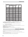
Tab. 1
L = Smooth plate R = Fluted plate LR = 50% smooth 50% fluted plate C = Chrome plate
*SUPPLY VOLTAGE: 3N AC 415 V; 3 AC 240 V; 1N 240 V 50/60 Hz.
N.B.: The input power with 3N AC 380 V; 3 AC 220 V; 1N 220 V 50/60 Hz is approximately 16% lower.
The input power with 3N AC 400 V; 3 AC 230 V; 1N 230 V 50/60 Hz is approximately 8% lower.
1. TECHNICAL DATA
2. INSTALLATION INSTRUCTIONS
EFT49L
EFT49LC
EFT49R
EFT49RC
EFT99L
EFT99LC
EFT99R
EFT99RC
EFT99LR
EFT99LRC
EFTA49L
EFTA99L
EFTA49LC
EFTA99LC
EFTA 49R
EFTA99R
EFTA49RC
EFTA99RC
MODEL DIMENSIONS in mm.
esternal plate
WxDxH/H max.
450x900x250/350
450x900x250/350
450x900x250/350
450x900x250/350
900x900x290/350
900x900x290/350
900x900x290/350
900x900x290/350
900x900x290/350
900x900x290/350
450x900x925
900X900X925
450X900X925
900X900X925
450X900X925
900x900x925
450X900X925
900X900X925
WxD
375x710
375x710
375x710
375x710
825x710
825x710
825x710
825x710
825x710
825x710
375x710
825X710
375X710
825X710
375X710
825x710
375X710
825X710
POWER
INPUT
TOTAL *
kW
6
6
6
6
12
12
12
12
12
12
6
12
6
12
6
12
6
12
WEIGHT
NET
kg
80
80
80
80
140
140
140
140
140
140
80
140
80
140
80
140
80
140

- 13 -
GB
2.1 ELECTRIC FRY-TOP DATA PLATE
The technical data plate is under the bottom
edge of the instrument panel.
2.2 LAWS, REGULATIONS AND TECHNICAL DIRECTIVES
The following regulations must be observed during installation:
- Current accident and fire regulations.
- The regulations of the electric power supply company.
- Health regulations.
- Electrical systems standards.
2.3 PLACE OF INSTALLATION
- The unit should be installed in a room with adequate ventilation.
- Install the unit in compliance with the safety regulations.
2.4 POSITIONING
- The various units may be installed separately or combined with other units in the DOMINA range.
- This unit is not suitable for encasing.
- The distance from the side walls must be at least 10 cm.; should the distance be less or the material of the walls or floor be
flammable, it is vital to install heat insulation.
2.5 ELECTRICAL CONNECTION
The electrical connection must be made in compliance with CEI standards, only by authorized and skilled personnel.
Firstly, check the data given in the technical data table of this manual, on the data plate and in the wiring diagram. The
envisaged connection is of the fixed type.
IMPORTANT: A multi-polar mains cut-off device must be provided upstream from each oven, with a contact gap of at least
3 mm., for example:
- a manual switch of suitable capacity, equipped with fuses
- circuit breaker with relevant miniature circuit breakers.
2.5.1 EARTHING
It is vital to earth the oven.
Connect the terminals marked by the symbols (
) positioned on the line-in terminal block to an efficient grounding
complying with the regulations in force.
SPECIFIC WARNINGS
The electrical safety of this unit is assured only when it is connected correctly to an effective earthing system as stated in
the current electrical safety standards; the manufacturer accepts no liability if these safety standards are not met.
It is necessary to verify this fundamental safety requisite and, in case of doubt, ask for the system to be tested thoroughly by
professionally qualified personnel.
The manufacturer cannot be deemed responsible for any damage caused by failure to earth the system.
CAUTION: NEVER CUT THE EARTH WIRE (yellow-green).
2.5.2 EQUIPOTENTIAL SYSTEM
The oven must be included in an equipotential system whose efficiency must be checked according to the standards in force.
The screw marked with the ”Equipotential” label is on the back near the cable clamp.
V
KW
HZ
Matr. N°
Mod.

- 14 -
GB
2.5.3 POWER SUPPLY CABLE
The unit is delivered fitted for one of the following voltages:
3N AC 380...415 V; 3 AC 220...240 V;1N AC 220...240 V 50/60 Hz.
The specifications of the power supply connection flexible cable must match or be superior to those of the cable with rubber
insulation H07RN-F. Introduce the cable through the cable clamp and secure it firmly. During operation, the power supply
voltage should not differ from the voltage rating by +/-10%.
To access the terminal block in order to connect the unit to a supply mains with different characteristics to the ones envisaged,
or to replace the supply cable, you need to:
- remove the front panel
- connect the supply cable to the terminal block according to need, following the instructions given on the label located near
the terminal block and in this handbook.
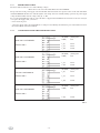
2.5.4 CONNECTIONS TO THE VARIOUS ELECTRIC MAINS
3N AC 380...415 V 50/60 Hz.
Elements 240 V
2N AC 380...415 V 50/60 Hz.
Elements 240 V
3 AC 220...240 V 50/60 Hz.
Elements 240 V
PE (Earth) yellow-green
N (NP) blue
L
3
(T) black
L
2
(S) black
L
1
(R) brown
PE (Earth) yellow-green
N (NP) blue
L
2
(S) black
L
1
(R) brown
PE (Earth) yellow-green
L
3
(T) black
L
2
(S) black
L
1
(R) brown
1N AC 220...240 V 50/60 Hz.
Elements 240 V
PE (Earth) yellow-green
N (NP) blue
L
1
(R) brown
Tab. 2

- 15 -
GB
The replacements described below should only be performed by an “Authorized Service Centre”.
Before replacing any component, you need to cut off power to the unit with the multi-polar switch.
A) Switch and thermostat
- remove the instrument panel
- undo the screws fastening the component
- disconnect the thermostat from the switch, carefully bending the two tabs of the bracket
- remove the thermostat bulb protection and take it out through the slit
- disconnect the wires, following the wiring diagram
- replace the component and reassemble everything, following the wiring diagram
- fit it all back together in reverse order to the above.
B) Heating elements
- disconnect the wires of the heating elements
- remove the heating element protection box
- remove the brackets fixing the heating element
- replace the part and reassemble everything, following the wiring diagram
Tab. 3
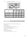
3. REPLACING THE MOST IMPORTANT COMPONENTS
1
2 3 4 5 6
380...415 V 3N
50/60 Hz
L1
L2 L3 N PE
L1
L2 N PE
380...415 V 2N 50/60 Hz
220...240 V 3 50/60 Hz
L1 N PE
220...240 V 50/60 Hz
L1
N PE
The electrical connection plate is placed near the terminal board.
MODEL
EFT49L EFT49LC
EFT49R EFT49RC
EFTA49L EFTA49LC
EFTA49R EFTA49RC
TYPE OF SUPPLY
3N AC 380...415 V 50/60 Hz.
2N AC 380...415 V 50/60 Hz.
3 AC 220...240 V 50/60 Hz.
1N AC 220...240 V 50/60 Hz.
Mass.
A/f.
N° cables
mm
2
8.3
16.66
14.4
25
5 x 1.5
4 x 2.5
4 x 1.5
3 x 4
Mass.
A/f.
N° cables
mm
2
16.66
33.32
28.86
50
5 x 2.5
4 x 6
4 x 4
3 x 10
EFT99L EFT99LC
EFT99R EFT99RC
EFT99LR EFT99LRC
EFTA99L EFTA99LC
EFTA99R EFTA99RC

- 16 -
GB
4.2 USING THE CHROME PLATE
SWITCHING ON: When the plate is just warm, grease it slightly with vegetable oil, then wait for the plate to reach the
required temperature.
COOKING: Optimum cooking is obtained at a temperature of approximately 200 ÷ 250°C. This temperature permits healthy
cooking without losing the main characteristics of the foods: taste, smell and appearance.
USE: The chrome plate does not absorb fat, as happens with traditional iron or cast-iron plates.
Cooking takes place all over the surface of the plate.
N.B. Never set the temperature higher than 250°C on the chrome plate.
4.3 SAFETY THERMOSTAT
The unit is equipped with a safety thermostat that limits the temperature in the event of the working thermostat malfunctioning.
To restore the safety thermostat, take off the rubber cap and press the red push-button.
Verify the causes of the action.
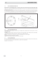
4.1 USING THE ELECTRIC FRY-TOP
Turn the thermostat control knob (Fig. 1 Pos. 1) clockwise to switch on the unit, shown by the green indicator light coming
on (Fig. 1 pos. 3). Continue turning the knob to set the required temperature as shown on the knob. The yellow indicator light
(Fig. 1 pos. 2) comes on to show that the plate heating elements are on; when it goes out, this means the temperature shown
on the knob has been reached.
The yellow indicator light comes back on whenever the required temperature on the plate has decreased by approximately
15°C and it will stay on until the plate reaches the required temperature again. To switch off, turn the knob anticlockwise to
take the “0” onto the limit position (indicator). The two yellow and green indicator lights will automatically go out.
4. USER INSTRUCTIONS
Fig. 1
3
2
1

- 17 -
GB
5. MAINTENANCE AND CLEANING
- Clean the stainless steel parts every day with warm soapy water, then rinse thoroughly and dry carefully.
- You must never clean the stainless steel with steel wool, wire brushes or common steel scrapers since they may deposit
ferrous particles that on oxidizing cause rust points. Stainless steel wool may be used applied in the direction of the satin
finish.
- If the unit is not to be used for a long time, give all the steel surfaces a good wipe over with a cloth lightly soaked in Vaseline
oil in order to apply a protective film. Periodically ventilate the premises.
COOKING TOP
Clean the plate frequently with a wet rag, then switch it on for a few minutes in order to dry it. Afterwards, coat it with a light
layer of Vaseline oil.
CHROME PLATES
Clean the plate frequently with a wet rag. To remove any incrustations, use a strong plastic scraper at an angle, then dry the
plate with a rag. Afterwards, lubricate it with a light layer of Vaseline oil.
NEVER SCRAPE WITH POINTED OR SHARP METAL OBJECTS!
Use plastic tools that can withstand the temperature or stainless steel spatulas with rounded edges.
Caution: Never use the scraper on its edge as this would score the plate irreparably impairing its operation and making it hard
to clean. Replace the blade if it is not perfectly sharp.
STAINLESS STEEL PARTS
The stainless steel parts must also be cleaned with soapy water and then dried with a soft cloth.
You can keep it shining brightly by periodically wiping it over with liquid (POLISH), an easily available product.

- 42 -
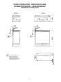
EFT49 EFT99
Uscita cavo elettrico
Electric cable output
Sortie câble électrique
Elektrischkabel ausgang
Salida cable eléctrico
SCHEMI DI INSTALLAZIONE - INSTALLATION DIAGRAM
SCHEMAS D’INSTALLATION - INSTALLATIONSPLÄNE
ESQUEMAS DE INSTALACIÓN

- 43 -
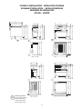
SCHEMI DI INSTALLAZIONE - INSTALLATION DIAGRAM
SCHEMAS D’INSTALLATION - INSTALLATIONSPLÄNE
ESQUEMAS DE INSTALACIÓN
EFTA49L - EFTA99R
7
00
850
150
0
80
925
880
900
70
850
80
925
8
80
900
600
450
700
850
150
0
80
925
900
880
900
900
6
00
7
0
85
150
0
80
93
0
880
900
90
0
6
00
45
700
8
50
150
0
80
925
880
900
4
50
600
4
50
Attacco gas G3/4”
Gas connection G3/4”
Raccord gaz G3/4”
Gasanschluß G3/4”
Toma de gas G 3/4”
C

- 44 -
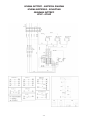
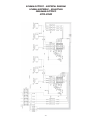
SCHEMA ELETTRICO - ELECTRICAL DIAGRAM
SCHEMA ELECTRIQUE - SCHALTPLAN
ESQUEMAS ELÉCTRICO
EFT49 - EFTA49

- 45 -
SCHEMA ELETTRICO - ELECTRICAL DIAGRAM
SCHEMA ELECTRIQUE - SCHALTPLAN
ESQUEMAS ELÉCTRICO
EFT99-EFTA99

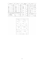
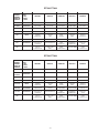
- 46 -

- 47 -
EFT49-EFTA49
EFT99-EFTA99
ABBREVIAZIONE
SHORTNAME
ABREVIATION
KURZZEICHEN
ABREVIACION
N° CODICE
CODE n°
N° CODE
Nr. CODEX
N° CODICO
ITALIANO
FRANCAIS
ENGLISH
DEUTSCH
M
R1-R2-R3-
R4-R5-R6
TL1-TL2
LV1-LV2
LG1-LG2
CO1-CO2
TS1-TS2
CA
RTBF900045
RTBF800038
RTBF600067
160505
160506
RTCU900007
RTCU800152
MORSETTIERA
RESISTENZA
TERMOSTATO 50-300°
LAMPADA VERDE
LAMPADA
ARANCIONE
COMMUTATORE
TERMOSTATO DI
SICUREZZA
CAVO DI
ALIMENTAZIONE
RACCORD
RESISTENCE
THERMOSTAT 50-300°
LAMPE VERTE
LAMPE
ORANGE
COMMUTATEUR
LIMITE
THERMOSTAT
CABLE
D’ALIMENTATION
TERMINAL BOARD
RESISTANCE
THERMOSTAT 50-300°
GREEN LAMP
ORANGE
LAMP
SWITCH
LIMIT THERMOSTAT
POWER SUPPLY
CABLE
KLEMMENLEISTE
HEITZKORPER
THERMOSTAT 50-300°
GRUENE LAMPE
ORANGE
LAMPE
HAUPTSCHATER
SICHERHEITS
THERMIOSTAT
ANSCHLUSSKABEL
ESPAÑOL
REGLETA
RESITENCIA
TERMOSTATO 50-300°
BOMBILLA VERDE
BOMBILLA
ANARANJADO
CONMUTADOR
TERMOSTATO
LIMITE
CABLE
D’ALIMENTACION
ABBREVIAZIONE
SHORTNAME
ABREVIATION
KURZZEICHEN
ABREVIACION
N° CODICE
CODE n°
N° CODE
Nr. CODEX
N° CODICO
ITALIANO
FRANCAIS
ENGLISH
DEUTSCH
M
R1-R2-R3
TL1
LV1
LG1
CO1
TS1
CA
RTBF900045
RTBF800038
RTBF600067
160505
160506
RTCU900007
RTCU800152
MORSETTIERA
RESISTENZA
TERMOSTATO 50-300°
LAMPADA VERDE
LAMPADA
ARANCIONE
COMMUTATORE
TERMOSTATO DI
SICUREZZA
CAVO DI
ALIMENTAZIONE
RACCORD
RESISTENCE
THERMOSTAT 50-300°
LAMPE VERTE
LAMPE
ORANGE
COMMUTATEUR
LIMITE
THERMOSTAT
CABLE
D’ALIMENTATION
TERMINAL BOARD
RESISTANCE
THERMOSTAT 50-300°
GREEN LAMP
ORANGE
LAMP
SWITCH
LIMIT THERMOSTAT
POWER SUPPLY
CABLE
KLEMMENLEISTE
HEITZKORPER
THERMOSTAT 50-300°
GRUENE LAMPE
ORANGE
LAMPE
HAUPTSCHATER
SICHERHEITS
THERMIOSTAT
ANSCHLUSSKABEL
ESPAÑOL
REGLETA
RESITENCIA
TERMOSTATO 50-300°
BOMBILLA VERDE
BOMBILLA
ANARANJADO
CONMUTADOR
TERMOSTATO
LIMITE
CABLE
D’ALIMENTACION

INFORMAZIONE AGLI UTENTI
AI SENSI delle Direttive 2002/95/CE, 2002/96/CE e 2003/108/CE, relative alla riduzione dell’uso di sostanze pericolose nelle
apparecchiature elettriche ed elettroniche, nonché allo smaltimento dei rifiuti.
Il simbolo del cassonetto barrato riportato sull’apparecchiatura o sulla confezione, indica che il prodotto alla fine della propria vita utile
deve essere raccolto separatamente dagli altri rifiuti.
La raccolta differenziata della presente apparecchiatura giunta a fine vita è organizzata e gestita dal produttore. L’utente che vorrà disfarsi
della presente apparecchiatura dovrà quindi contattare il produttore e seguire il sistema che questo ha adottato per consentire la raccolta
separata dell’apparecchiatura giunta a fine vita.
L’adeguata raccolta differenziata per l’avvio successivo dell’apparecchiatura dismessa al riciclaggio, al trattamento e allo smaltimento
ambientalmente compatibile contribuisce ad evitare possibili effetti negativi sull’ambiente e sulla salute e favorisce il reimpiago e/o riciclo
dei materiali di cui è composta l’apparecchiatura.
Lo smaltimento abusivo del prodotto da parte del detentore comporta l’applicazione delle sanzioni amministrative previste dalla normativa vigente.
USER INFORMATION
Pursuant to the 2002/95/CE, 2002/96/CE and 2003/108/CE Directives concerning the reduction in the utilisation of dangerous
substances in electric and electronic equipment, as well as waste disposal.
The symbol of the crossed rubbish skip on the equipment or on the package indicates that the product must be separated from other
waste at the end of its useful life.
The differentiated collection of this equipment is organised and managed by the producer. The user who intends to get rid of this equipment
shall contact the producer and follow the system that the latter has used in order to collect the equipment separately at the end of its life.
The proper differentiated collection in order to start the following recycling, treatment and disposal of the disused equipment in
compliance with the environment helps to avoid possible negative effects on the environment and on health, and favours the reutilisation
and/or recycling of the materials forming the equipment.
The unauthorised disposal of the product by the holder implies applying administrative penalties provided by the regulations in force.
INFORMATIONS DESTINÉES AU CLIENT
Conformément aux Directives 2002/95/CE, 2002/96/CE et 2003/108/CE concernant la réduction des substances dangereuses
dans les appareils électriques et électroniques ainsi que le traitement des déchets.
Le pictogramme de la benne barrée reportée sur l’appareil ou sur l’emballage indique que l’appareil, à la fin de sa vie, doit être traité sé-
parément des autres déchets.
La collecte différentiée de cet appareil ayant atteint la fin de sa vie est organisée et gérée par le fabricant. Le client souhaitant se défaire de cet appareil
devra donc contacter le fabricant et suivre la procédure que ce dernier a adoptée afin de permettre la collecte séparée de l’appareil arrivé en fin de vie.
La collecte différentiée adéquate permettant le recyclage successif de l’appareil et un traitement compatible avec l’environnement contri-
bue à prévenir les impacts négatifs sur l’environnement et la santé des personnes ainsi qu’à favoriser la réutilisation et/ou le recyclage
des matériaux qui composent l’appareil.
Le traitement illégal de l’appareil par son propriétaire entraîne l’application des sanctions administratives prévues par la législation en vigueur.
INFORMATION FÜR DIE BENUTZER
IM SINNE der Richtlinien 2002/95/EG, 2002/96/EG und 2003/108/EG zur Beschränkung der Verwendung bestimmter gefähr-
licher Stoffe in Elektro- und Elektronikgeräten und zur Entsorgung der Abfälle.
Das auf dem Gerät oder auf der Packung vorhandene Symbol eines gekreuzten Müllcontainers weist darauf hin, dass das Produkt nach
Ende seiner Nutzungsdauer von anderen Abfällen getrennt zu sammeln ist.
Die getrennte Sammlung dieses Geräts nach Ende seiner Nutzungsdauer wird vom Hersteller organisiert und verwaltet. Der Benutzer,
der sich von diesem Gerät befreien will, muss sich daher mit dem Hersteller in Verbindung setzen und das System befolgen, das der
Hersteller für die getrennte Sammlung des Geräts nach Ende seiner Nutzungsdauer eingeführt hat.
Eine angemessene getrennte Sammlung für die spätere Zuführung des abgelegten Geräts zum Recyling, zur Behandlung und zur um-
weltfreundlichen Entsorgung trägt dazu bei, mögliche negativen Auswirkungen auf die Umwelt und auf die Gesundheit zu vermeiden
und begünstigt die Wiederverwertung und/oder das Recycling der Werkstoffe, aus denen das Gerät besteht.
Eine rechtswidrige Produktentsorgung durch den Besitzer führt zur Auferlegung der von den einschlägigen Normvorschriften vorgese-
henen Verwaltungssanktionen.
INFORMACIÓN A LOS USUARIOS
Según las Directivas 2002/95/CE, 2002/96/CE y 2003/108/CE, relativas a la reducción del uso de sustancias peligrosas en los
aparatos eléctricos y electrónicos, así como a la gestión de los residuos.
El símbolo del contenedor tachad que aparece en los aparatos o en los envases, indica que el producto, al final de su vida útil debe
recogerse separado de los otros residuos.
La recogida diferenciada de este aparato una vez llegado el fin de su vida útil es organizada y gestionada por el productor. El usuario que
desee deshacerse de este aparato deberá, pues, ponerse en contacto con el productor y seguir el sistema adoptado por éste para permitir la
recogida separada del aparato al final de su vida útil.
La adecuada recogida diferenciada para el posterior reciclaje, tratamiento y desguace ambientalmente compatible del aparato contribuye a evitar
posibles efectos negativos sobre el ambiente y la salud y favorece la reutilización o el reciclaje de los materiales de que está compuesto el aparato.
El desguace abusivo del producto por parte del propietario comporta la aplicación de las sanciones administrativas previstas por la normativa vigente.
I
GB
F
D
E
-
 1
1
-
 2
2
-
 3
3
-
 4
4
-
 5
5
-
 6
6
-
 7
7
-
 8
8
-
 9
9
-
 10
10
-
 11
11
-
 12
12
-
 13
13
-
 14
14
-
 15
15
-
 16
16


Hobart EFT49L Installation, Use And Maintenance Instructions
- Tipo
- Installation, Use And Maintenance Instructions
in altre lingue
- English: Hobart EFT49L
Documenti correlati
Altri documenti
-
Diamond EERV Installation, Use And Maintenance Instructions
-
Bartscher 296215 Istruzioni per l'uso
-
MBM GF99T Installation, Use And Maintenance Instructions
-
Bartscher 296630 Istruzioni per l'uso
-
Bartscher 296510 Istruzioni per l'uso
-
Lofra PB96MFT/C Manuale del proprietario
-
Bartscher 2952481 Istruzioni per l'uso
-
Bartscher 296311 Istruzioni per l'uso