Rockford Fosgate PunchPM282HW-B Installation & Operation
- Categoria
- Altoparlanti
- Tipo
- Installation & Operation
Questo manuale è adatto anche per

Installation & Operation
Serial Number: Date of Purchase:
PM282W • PM282W-B
PM282HW • PM282HW-B
®
WAKE TOWER
SPEAKERS
Installation assistance available at:
www.rockfordfosgate.com/rftech
ROCKFORDFOSGATE.COM
600 South Rockford Drive • Tempe, Arizona 85281 United States
Direct: (480) 967-3565 • Toll Free: (800) 669-9899
Printed in China
112114
1230-58912-01

32
Dear Customer,
Congratulations on your purchase of the world’s finest brand of audio
products. At Rockford Fosgate we are fanatics about musical reproduc-
tion at its best, and we are pleased you chose our product. Through
years of engineering expertise, hand craftsmanship and critical testing
procedures, we have created a wide range of products that reproduce
music with all the clarity and richness you deserve.
For maximum performance we recommend you have your new Rockford
Fosgate product installed by an Authorized Rockford Fosgate Dealer,
as we provide specialized training through Rockford Technical Training
Institute (RTTI). Please read your warranty and retain your receipt and
original carton for possible future use.
Great product and competent installations are only a piece of the puzzle
when it comes to your system. Make sure that your installer is using
100% authentic installation accessories from Rockford Fosgate in your
installation. Rockford Fosgate has everything from RCA cables and
speaker wire to power wire and battery connectors. Insist on it! After all,
your new system deserves nothing but the best.
To add the finishing touch to your new Rockford Fosgate image, order
your Rockford accessories, which include everything from T-shirts to
hats.
Visit our web site for the latest information on all Rockford products;
www.rockfordfosgate.com
or, in the U.S. call 1-800-669-9899 or FAX 1-800-398-3985. For all other
countries, call +001-480-967-3565 or FAX +001-480-966-3983.
Table of Content
If, after reading your manual, you still have questions regarding this prod-
uct, we recommend that you see your Rockford Fosgate dealer. If you need
further assistance, you can call us direct at 1-800-669-9899. Be sure to
have your serial number, model number and date of purchase available
when you call.
Safety
This symbol with “WARNING” is intended
to alert the user to the presence of important
instructions. Failure to heed the instructions
will result in severe injury or death.
This symbol with “CAUTION” is intended to
alert the user to the presence of important
instructions. Failure to heed the instructions
can result in injury or unit damage.
• To prevent injury and damage to the unit, please read and follow the
instructions in this manual. We want you to enjoy this system, not get
a headache.
• If you feel unsure about installing this system yourself, have it installed
by a qualified Rockford Fosgate technician.
• Before installation, disconnect the battery negative (-) terminal to
prevent damage to the unit, fire and/or possible injury.
Introduction
Specifications
©2014 Rockford Corporation. All Rights Reserved. ROCKFORD FOSGATE, PUNCH
®
and associated logos where applicable are registered trademarks of Rockford
Corporation in the United States and/or other countries. All other trademarks are the property of their respective owners. Specifications subject to change without notice.
2 Introduction
3-4 Specifications
5 Installation
Installation Considerations
Mounting
6-7 Additional Languages
French
Spanish
German
Italian
8 Limited Warranty Information
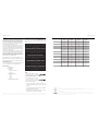
Model PM282W PM282W-B PM282HW PM282HW-B
Nominal Diameter - inch
(mm)
8
(203)
8
(203)
8
(203)
8
(203)
Description
2-Way 2-Way 2-Way 2-Way
Nominal Impedance (Ohms)
4Ω 4Ω 4Ω 4Ω
Frequency Response (Hz)
40-20kHz 40-20kHz 63-22kHz 63-22kHz
Voice Coil Diameter - inch
(mm)
1.25
(32.3)
1.25
(32.3)
2
(50.8)
2
(50.8)
Power Handling - Watts
(RMS/Peak)
100/200 100/200 150/300 150/300
Fs - Free Air Resonance (Hz)
50 50 84.5 84.5
Qts
0.57 0.57 0.58 0.58
Vas - cu. ft.
(Liter)
1.06
(30)
1.06
(30)
0.39
(11)
0.39
(11)
Sensitivity (1W/1M)
90dB 90dB 93dB 93dB
Sensitivity (2.83V/1M)
93dB 93dB 96dB 96dB
Xmax - inch
(mm)
0.28
(7)
0.28
(7)
0.04
(1)
0.04
(1)
Grille/Trim Ring
YES YES YES YES
CEA 2031
Power handling on Rockford Fosgate speakers conform to CEA-2031 industry standards. This means your speaker has the capacity to handle
power under continuous demand, not instantaneous power handling that over time can damage voice coils.
VERIFIED WITH KLIPPEL
To adorn the ‘Verified with Klippel’ mark, the qualifying company’s loudspeaker engineering personnel must be trained and certified by
Klippel prior to using the three separate Klippel systems to design, develop and test. Rockford Fosgate has made the investment in Klippel to
deliver the best possible speakers and subwoofers to their customers.
PRACTICE SAFE SOUND
Continuous exposure to sound pressure levels over 100dB may cause
permanent hearing loss. High powered auto sound systems may
produce sound pressure levels well over 130dB. Use common sense
and practice safe sound.
PRATIQUEZ UNE ÉCOUTE SANS RISQUES
Une exposition continue à des niveaux de pression acoustique upérieurs à
100 dB peut causer une perte d’acuité auditive permanente. Les systèmes
audio de forte puissance pour auto peuvent produire des niveaux de
pression acoustique bien au-delà de 130 dB. Faites preuve de bon sens et
pratiquez une écoute sans risques
PRACTIQUE EL SONIDO SEGURO
El contacto continuo con niveles de presión de sonido superiores a 100
dB puede causar la pérdida permanente de la audición. Los sistemas de
sonido de alta potencia para automóviles pueden producir niveles de
presión de sonido superiores a los 130 dB. Aplique el sentido común y
practique el sonido seguro.
PRAKTIZIEREN SIE SICHEREN SOUND
Fortgesetzte Geräuschdruckpegel von über 100 dB können beim
Menschen zu permanentem Hörverlust führen. Leistungsstarke
Autosoundsysteme können Geräuschdruckpegel erzeugen, die weit über
130 dB liegen. Bitte wenden Sie gesunden Menschenverstand an und
praktizieren Sie sicheren Sound.
OSSERVATE LE REGOLE DEL SUONO SENZA PERICOLI
La costante esposizione a livelli di pressione acustica al di sopra dei
100dB possono causare la perdita permanente dell’udito. I sistemi
audio ad alta potenza possono produrre livelli di pressione acustica ben
superiori ai 130dB. Si consiglia il buon senso e l’osservanza delle regole
del suono senza pericoli

54
Specifications
illus.-1.1
Typical Installation
Installation
Contents
Installation Considerations
Before beginning any installation, follow these simple rules:
1. Be sure to carefully read and understand the instructions before
attempting to install these speakers.
2. For safety, disconnect the negative lead from the battery prior to
beginning the installation.
3. For easier assembly, we suggest you run all wires prior to mounting
your speakers in place.
4. Use high quality connectors for a reliable installation and to minimize
signal or power loss.
5. Think before you drill! Be careful not to cut or drill into gas tanks, fuel
lines, brake or hydraulic lines, vacuum lines or electrical wiring when
working on any vehicle. If installation in a boat, take care not to cut or
drill through the main hull.
6. Never run wires underneath the vehicle. Running the wires inside the
vehicle or hull area provides the best protection.
7. Avoid running wires over or through sharp edges. Use rubber or
plastic grommets to protect any wires routed through metal, especially
the firewall.
Mounting
1. Determine where the speakers will be mounted. Be sure that the
mounting location has sufficient clearance in all direction for the
speaker to swivel; conduct a full rotation to ensure there is not
obstruction.
2. Mark the locations on the underside of the mounting surface for the
speaker mount and wire harness. Drill 5/16” holes for the mounting
bolts and a 7/16” for the wire harness. If you want to surface mount
the wiring, use the notch provided in the mount instead of drilling
the hole.
3. Insert the supplied grommet and feed the wire harness through.
Be sure to observe proper polarity when connecting the wires. The
speaker harness’s negative wire is indicated with a “black stripe”.
4. Feed the speaker harness through the mount. Using the supplied
hardware, through bolt and tighten the mount securing it. Be sure to
connect the safety lanyard to the mount during this process.
5. Using the security torx bolt, slide the speaker enclosure onto the
mount and tighten. Connect the other end of the safety lanyard to the
security torx prior to tightening.
6. To swivel speaker, loosen security torx until speaker can swivel freely.
Be sure to tighten once desired position is achieved.
Note: For tubular mounting applications, a Tower Speaker Clamp will be
required. (PM-CL1/PM-CL1B)
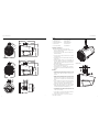
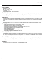
illus.-2.1
• (2) Marine Grade Speakers
• (2) Mounting Couplers
• (2) Molex Speaker Harnesses
• (2) Wire Grommets
• (1) Security Torx Wrench
• (2) Security Torx Bolts
• (4) Mounting Bolts
• (4) Mounting Bolt Nuts
• (2) Safety Lanyards
• (2) Layard Washers
PM282HW/PM282HW-B
PM282W/PM282W-B
7.8” Dia
(197mm)
1.7”
(44mm)
0.6”
(16mm)
14.2”
(360mm)
8.3”
(211mm)
6.8”
(174mm)
3.3”
(84mm)
2.5”
(64mm)
10.9”
(277mm)
5.9”
(150mm)
9.1”
(230mm)
37.5°
52.5°
7.8” Dia
(197mm)
14.2”
(360mm)
8.3”
(211mm)
6.8”
(174mm)
10.9”
(277mm)
5.9”
(150mm)
9.1”
(230mm)
37.5°
52.5°

76
Français Español
Considérations Concernant L’installation
Avant de commencer l’installation, suivez les règles ci-dessous:
1. Veillez à bien lire et comprendre les instructions avant d’essayer d’installer
les haut-parleurs.
2. Par mesure de sécurité, débranchez le fil négatif de la batterie avant de
commencer l’installation.
3. Pour faciliter le montage des haut-parleurs, il est conseillé d’installer tous
les câbles au préalable.
4. Utilisez des connecteurs de haute qualité pour assurer une installation
fiable et réduire au minimum la perte de signal ou de puissance.
5. Réfléchissez bien avant de percer.Veillez à ne pas couper ou percer le
réservoir d’essence, le câblage électrique ou les conduites de carburant,
de freinage hydraulique ou de dépression en travaillant sur un véhicule.
En cas d’installation sur un bateau, veillez à ne pas couper ou percer la
coque principale.
6. Ne jamais faire passer de fils sous le véhicule. Leur installation à l’intérieur
du véhicule ou de la coque assure la meilleure protection.
7. Évitez de faire passer des fils sur des bords tranchants ou dans des
orifices à arêtes vives. Utilisez des bagues en caoutchouc ou en plastique
pour protéger les fils traversant une plaque de métal, notamment le
tablier.Emplacements De Montage
Montage
1. Déterminer l’endroit de montage des haut-parleurs. S’assurer que
l’emplacement de montage a suffisamment de dégagement dans tous
les sens pour que le haut-parleur puisse pivoter; exécuter une rotation
complète pour s’assurer qu’il n’y pas d’obstruction.
2. Marquer les emplacements sur le dessous de la surface de montage pour
le support de haut-parleur et le faisceau électrique. Percer des trous de
5/16” pour les boulons de fixation et un trou de 7/16” pour le faisceau
électrique. Pour monter le faisceau de fils en surface, utiliser l’encoche
fournie dans le support au lieu de percer le trou.
3. Insérer le passe-câble fourni et y faire passer le faisceau électrique.
S’assurer d’observer la polarité appropriée lors de la connexion des fils.
Le fil négatif du faisceau électrique de haut-parleur est indiqué par une
« rayure noire ».
4. Acheminer le faisceau électrique à travers le support. À l’aide de la visserie
fournie, du boulon traversant et serrer le support pour le fixer. S’assurer
de connecter la lanière de sécurité au support pendant ce processus.
5. À l’aide du boulon Torx de sécurité, faire glisser le boîtier de haut-parleur
sur le support et serrer. Connecter l’autre extrémité de la lanière de
sécurité au boulon Torx de sécurité avant de serrer.
6. Pour faire pivoter le haut-parleur, desserrer le boulon Torx de sécurité
jusqu’à ce que le haut-parleur puisse pivoter librement. S’assurer de
serrer une fois la position souhaitée obtenue.
Remarque : Pour les applications de fixation tubulaire, un collier de haut-parleur
de tour sera requis. (PM-CL1/PM-CL1B)
Consideraciones para la instalación
Antes de comenzar cualquier instalación, siga estas simples normas:
1. 1. Asegúrese de leer cuidadosamente y de entender las instrucciones
antes de tratar de instalar estos altavoces.
2. Por seguridad, desconecte el conductor negativo de la batería antes de
comenzar la instalación.
3. Para facilitar el montaje, sugerimos que tienda todos los cables antes de
montar sus altavoces en su sitio.
4. Utilice conectores de alta calidad para tener una instalación confiable y
para reducir al mínimo las pérdidas de señal o de potencia.
5. ¡Piense siempre antes de perforar! Tenga cuidado de no cortar ni perforar
en tanques de combustible, tuberías de combustible, frenos o hidráulicas,
tuberías de vacío o cableado eléctrico al trabajar en un vehículo. Si la
instalación se hace en un bote, tenga cuidado de no cortar ni perforar a
través del casco principal.
6. Nunca tienda cables abajo del vehículo.Tender los cables adentro del
vehículo o casco proporciona la mejor protección.
7. Evite tender cables arriba o a través de bordes filosos. Use arandelas
aislantes de caucho para proteger los cables tendidos a través de metal,
especialmente la mampara cortafuegos.Montage
Montaje
1. Determine dónde se montará los altavoces. Asegúrese de que la localidad
de montaje tenga suficiente espacio libre en todas las direcciones para
que el altavoz bascule; hágalo dar toda una vuelta para asegurarse de que
no haya obstrucciones.
2. Marque las localidades en el lado inferior de la superficie de montaje
para el soporte del altavoz y del arnés de cables. Perfore agujeros de
5/16 pulg. para los pernos de montaje y uno de 7/16 pulg. para el arnés
de cables. Si desea montar el cableado en la superficie, use la muesca
proporcionada en el soporte en vez de perforar el agujero.
3. Inserte las arandelas de caucho proporcionadas y pase el arnés de cable a
través de las mismas. Asegúrese de usar la polaridad correcta al conectar
los cables. Se ha identificado el cable negativo del arnés con una “franja
negra”.
4. Pase el arnés del altavoz a través del soporte. Usando el hardware
proporcionado y el perno pasante, apriete el soporte asegurándolo.
Asegúrese de conectar el cordón de seguridad al soporte durante este
proceso.
5. Usando el perno torx de seguridad, deslice la caja del altavoz sobre el
soporte y apriete. Conecte el otro extreme del cordón de seguridad al torx
de seguridad antes de apretar.
6. Para hacer bascular el altavoz, suelte el trox de seguridad hasta que se
pueda hacer bascular libremente el altavoz. Asegúrese de apretarlo una
vez alcanzada la posición deseada.
Nota: Para las aplicaciones de montaje tubular, se requerirá una abrazadera para
altavoz de torre. (PM-CL1/PM-CL1B)
Deutsch
Einbauüberlegungen
Befolgen Sie vor dem Einbau diese einfachen Regeln:
1. 1. Lesen Sie die Anleitung sorgfältig, bevor Sie versuchen diese
Lautsprecher einzubauen.
2. Entfernen Sie vor dem Einbau aus Sicherheitsgründen das negative Kabel
von der Batterie.
3. Um die Montage zu erleichtern, empfehlen wir alle Kabel vor der
Befestigung Ihrer Lautsprecher zu verlegen.
4. Verwenden Sie nur Qualitätsstecker, um einen zuverlässigen Einbau zu
gewährleisten und Signal- und Stromverlust zu minimieren.
5. Denken Sie nach, bevor Sie bohren! Achten Sie darauf, nicht
in den Benzintank, die Benzin-, Brems- oder hydraulischen
Leitungen,Vakuumleitungen oder Elektrokabel zu schneiden oder zu
bohren,wenn Sie am Fahrzeug arbeiten.Achten Sie beim Einbau in einem
Boot darauf, nicht durch den Bootsrumpf zu schneiden oder zu bohren.
6. Verlegen Sie Kabel nie unter dem Fahrzeug. Die Kabel im Fahrzeug oder
Bootsrumpf zu verlegen, bietet den besten Schutz.
7. Vermeiden Sie es, Kabel über scharfe Kanten zu verlegen.Verwenden
Sie Gummi- oder Plastikringe, um Kabel zu schützen, die durch Metall
verlegt werden (besonders die Feuerwand).
Befestigung
1. Entscheiden Sie wo die Lautsprecher montiert werden sollen. Prüfen
Sie, dass die Stelle auf allen Seiten genug Freiraum hat, damit der
Lautsprecher in alle Richtungen gedreht werden kann; drehen Sie ihn
einmal um die ganze Achse um sicherzustellen, dass er nicht blockiert
wird.
2. Markieren Sie die Stelle auf der Unterseite der Montagefläche für die
Lautsprecherhalterung und den Kabelbaum. Bohren Sie 5/16 Zoll (0,8
cm) Löcher für die Befestigungsschrauben und ein 7/16 Zoll (1,1 cm)
Loch für den Kabelbaum. Wenn Sie den Kabelsatz auf der Oberfläche
anbringen möchten, benutzen Sie die bereits bestehende Kerbe anstatt
ein Loch zu bohren.
3. Drücken Sie die beiliegende Tülle in das Loch und schieben Sie den
Kabelbaum hindurch. Beim Anschließen der Drähte die richtige Polarität
beachten! Das Minuskabel des Lautsprecher-Kabelsatzes ist durch einen
“schwarzen Streifen” gekennzeichnet.
4. Schieben Sie den Kabelsatz des Lautsprechers durch die Montagefläche.
Benutzen Sie die beiliegenden Befestigungsteilen und schieben Sie
die Schraube durch und befestigen Sie sie auf der anderen Seite der
Montagefläche. Prüfen Sie, dass das Sicherungskabel bei diesem Schritt
auch auf der Montagefläche befestigt wird.
5. Mithilfe der Sicherheits-Torx-Schraube schieben Sie das
Lautsprechergehäuse auf die Montagefläche und befestigen Sie es.
Verbinden Sie das andere Ende des Sicherungskabels mit der Sicherheits-
Torx-Schraube und ziehen Sie sie fest.
6. Um den Lautsprecher zu schwenken, lösen Sie die Sicherheits-Torx-
Schraube bis der Lautsprecher sich frei drehen lässt. Nachdem Sie die
gewünschte Position gefunden haben, ziehen Sie die Schraube wieder
fest.
Hinweis: Für Rohrsysteme ist eine Lautsprecher-Klemmschraube erforderlich.
(PM-CL1/PM-CL1B)
Italiano
Considerazioni sull’installazione
Prima di iniziare qualsiasi operazione d’installazione, vi consigliamo di se-
guire queste semplici regole:
1. Assicuratevi di aver letto tutte le istruzioni con cura e di averle capite prima
di effettuare qualsiasi tentativo d’installazione neiconfronti dell’unità.
2. Per motivi di sicurezza, scollegate il cavo negativo dalla batteria prima di
dare l’avvìo all’installazione.
3. Per facilitare il montaggio, vi suggeriamo di far scorrere tutti i fili prima di
montare la vostra unità nella sua ubicazione.
4. Usate connettori di alta qualità per garantire un’installazione che dà
affidamento e per ridurre al minimo la perdita di segnali o di potenza.
5. State attenti prima di trapanare! Cercate di non trapanare e di non incidere
i serbatoi della benzina; le condutture del carburante, dei freni, del sistema
idraulico e a depressione; nonché i fili elettrici quando state lavorando su
qualsiasi veicolo.
6. Non fate mai scorrere i fili sotto il veicolo.Avrete la protezione migliore
faccendo scorrere i fili all’interno del veicolo.
7. Evitate di far scorrere i fili sopra o attraverso delle estremità affilate. Usate
guarnizioni di tenuta in gomma o in plastica per proteggere qualsiasi filo
che passi attraverso del metallo, soprattutto il parafiamma.
Montaggio
1. Stabilire dove verranno montati i diffusori. Accertarsi che la posizione di
montaggio prescelta abbia spazio sufficiente in tutte le direzioni per poter
ruotare il diffusore; effettuare una rotazione completa per accertarsi che
non vi sia alcuna ostruzione.
2. Contrassegnare le posizioni sul lato inferiore della superficie di
montaggio per la base del diffusore e il cablaggio di collegamento.
Trapanare dei fori da 0,8 cm per i bulloni di montaggio e da 1,11 cm per il
cablaggio di collegamento. Per il montaggio su superficie del cablaggio
usare l’incisione che si trova nel supporto invece di trapanare un foro.
3. Inserire l’anello accluso e condurre il cablaggio di collegamento.
Accertarsi di rispettare la polarità corretta quando si collegano i cavi. Il
filo negativo del cablaggio del diffusore è indicato con una “striscia nera”.
4. Condurre il cablaggio del diffusore attraverso il montaggio. Con la
bulloneria acclusa e la vite passante avvitare il montaggio e serrarlo.
Accertarsi di collegare il cordino di sicurezza al montaggio in questo
passo.
5. Utilizzando la vite di sicurezza Torx infilare la cassa del diffusore sul
montaggio e serrarla. Collegare l’altra fine del cordino di sicurezza alla
vite di sicurezza Torx prima di serrarla.
6. Per ruotare il diffusore, allentare la vite di sicurezza Torx fino a quando il
diffusore può ruotare liberamente. Accertarsi di serrarla nella posizione
desiderata.
Nota: Per applicazioni di montaggio tubolare è necessario un morsetto per dif-
fusori Tower. (PM-CL1/PM-CL1B)

8
Rockford Corporation offers a limited warranty on Rockford Fosgate products on the following terms:
Length of Warranty
POWER Amplifiers – 2 Years
BMW
®
Direct Fit Speakers – 2 Years
All other products - 1 Year
Any Factory Refurbished Product – 90 days (receipt required)
What is Covered
This warranty applies only to Rockford Fosgate products sold to consumers by Authorized Rockford Fosgate Dealers in the United States of America or its
possessions. Product purchased by consumers from an Authorized Rockford Fosgate Dealer in another country are covered only by that country’s Distribu-
tor and not by Rockford Corporation.
Who is Covered
This warranty covers only the original purchaser of Rockford product purchased from an Authorized Rockford Fosgate Dealer in the United States. In order
to receive service, the purchaser must provide Rockford with a copy of the receipt stating the customer name, dealer name, product purchased and date of
purchase.
Products found to be defective during the warranty period will be repaired or replaced (with a product deemed to be equivalent) at Rockford’s discretion.
What is Not Covered
1. Damage caused by accident, abuse, improper operations,water, theft, shipping.
2. Any cost or expense related to the removal or reinstallation of product.
3. Service performed by anyone other than Rockford or an Authorized Rockford Fosgate Service Center.
4. Any product which has had the serial number defaced, altered, or removed.
5. Subsequent damage to other components.
6. Any product purchased outside the U.S.
7. Any product not purchased from an Authorized Rockford Fosgate Dealer.
Limit on Implied Warranties
Any implied warranties including warranties of fitness for use and merchantability are limited in duration to the period of the express warranty set forth
above. Some states do not allow limitations on the length of an implied warranty, so this limitation may not apply. No person is authorized to assume for
Rockford Fosgate any other liability in connection with the sale of the product.
How to Obtain Service
Contact the Authorized Rockford Fosgate Dealer you purchased this product from. If you need further assistance, call 1-800-669-9899 for Rockford Cus-
tomer Service. You must obtain an RA# (Return Authorization number) to return any product to Rockford Fosgate. You are responsible for shipment of
product to Rockford.
EU Warranty
This product meets the current EU warranty requirements, see your Authorized dealer for details.
Warranty
-
 1
1
-
 2
2
-
 3
3
-
 4
4
-
 5
5


Rockford Fosgate PunchPM282HW-B Installation & Operation
- Categoria
- Altoparlanti
- Tipo
- Installation & Operation
- Questo manuale è adatto anche per
in altre lingue
- English: Rockford Fosgate PunchPM282HW-B
- français: Rockford Fosgate PunchPM282HW-B
- español: Rockford Fosgate PunchPM282HW-B
- Deutsch: Rockford Fosgate PunchPM282HW-B
Documenti correlati
-
 Rockford Fosgate ELEMENT READY M0-65 Manuale utente
-
Rockford Fosgate Prime RM0652B Installation & Operation
-
Rockford Fosgate M2WL-10H Manuale del proprietario
-
Rockford Fosgate M2-65B Installation & Operation Manual
-
 Rockford Fosgate M2WL-8 Manuale utente
-
Rockford Fosgate M1WL-65MB Istruzioni per l'uso
-
Rockford Fosgate Prime R14X2 Manuale del proprietario
-
 Rockford Fosgate T3-BMW-SUB Installation & Operation
-
 Rockford Fosgate RFK-HD9813M5 Harley-Davidson Street-Road Glide Amplifier Manuale utente
-
 Rockford Fosgate M2 ELEMENT READY M2D2-10SB Manuale utente


