
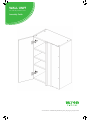
WALL UNIT
600 Tall Adjustable Corner
Assembly Guide
For Internal Use: FI.WR.INS.048_WKIN00133_WALL_600_Adj_Cnr_Tall_Rev2.indd

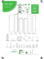
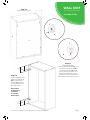
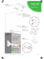
Hanging Bracket
X2 Inc Screws
Hanging Bracket Plate
X2 (Screws Not Included)
Hinge Mounting Plate
X2 Inc Screws
Hinge
X2 Inc Screws
Corner Gusset
X2
Hanging Bracket
Cover cap
x2
BEFORE YOU START
INSTALLATION
SHOULD BE
PERFORMED BY A
COMPETENT
PERSON ONLY.
THIS PRODUCT COULD
BE DANGEROUS
IF INCORRECTLY
INSTALLED
REQUIRED TOOLS
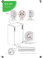
NOT to be used
with CAM DOWEL
& CAM LOCK
Panel B
x2 End Panel
Loose Shelf
x3
Blanking Panel
x1
Frontal (packed separately)
x1
Panel A
x1 Back Panel
Panel C
x2 Base Panel
(F) x8
Wooden Dowel
(G) x8
Cam Dowel
(Expanding)
(H) x8
Cam Lock
(K) x4
30mm
Screw
(L) x21
15mm
Screw
(S) x4
20mm
Screw
(M) x2
Cover Cap
(R) x2
L Bracket
(N) x1
Door
Buer
(O) x12
Shelf Peg
Plastic
(T) x10
Back Panel
Support Clip
View from underside
For Internal Use: FI.WR.INS.048_WKIN00133_WALL_600_Adj_Cnr_Tall_Rev2.indd
Page 1
WALL UNIT
600 Tall Adjustable Corner
Assembly Guide

Step 1.
Seat dowel (F)
into holes in
both end panels (B)
as shown.
Step 2.
Seat cam dowel (G)
into holes in both end
panels (B) as shown.
Dowel (F)
& Cam Dowel (G)
Location Detail
Step 3.
Carcass construction
Attach panels x2 (C) to
panel (B), using cam
dowels (G) & cam locks
(H) (in blue), and also
using dowels (F)
(in orange) in positions
as shown.
All Cam Lock (H) are to be positioned facing
the outside of the unit carcass, for ease of tightening.
Step 5.
Insert cam lock (H). Hand
tighten all cam locks
(H), this will expand cam
dowels (G) and tighten the
unit together.
Seat (G)
cam dowel
into hole
as shown
Do not use power tools with
cam dowel (G) or cam lock (H)
C
C
A
B
Step 4.
Slide panel (A) into the
groove of panels (B) & (C).
G
G
F
F
F
F
G
G
B
B
C
H
H
G
G
View from underside View from underside
For Internal Use: FI.WR.INS.048_WKIN00133_WALL_600_Adj_Cnr_Tall_Rev2.indd
Page 2
WALL UNIT
600 Tall Adjustable Corner
Assembly Guide

Step 8.
Carcass construction
Attach panel (B) to
panels (C) using cam
dowel (G) & cam lock (H)
(in blue), and also using
dowels (F) (in orange)
in positions as shown.
Ensure panel (A) is
seated into the groove of
panel (B).
All cam lock (H) are to be positioned facing
the outside of the unit carcass, for ease of tightening.
Do not use power tools with
cam dowel (G) or cam lock (H)
Step 9.
Cam lock (H)
Insert cam lock (H). Hand
tighten all cam locks (H), this
will expand cam dowels (G) and
tighten the unit together.
C
C
H
H
A
B
B
Step 6.
Seat dowel (F)
into holes in
both end panels (B)
as shown.
Step 7.
Seat cam dowel (G)
into holes in both end
panels (B) as shown.
Seat (G)
cam dowel
into hole
as shown
G
G
F
F
F
F
G
G
B
View from underside
View from underside
B
C
C
H
H
G
G
Dowel (F)
& Cam Dowel (G)
Location Detail
For Internal Use: FI.WR.INS.048_WKIN00133_WALL_600_Adj_Cnr_Tall_Rev2.indd
Page 3
WALL UNIT
600 Tall Adjustable Corner
Assembly Guide

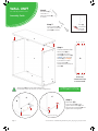
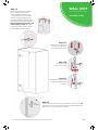
Step 10.
Ensure carcass is square.
Step 11.
Back Panel Clips
Slide the back panel clips (T) into
the groove of both panels (B).
The back panel clips (T) should
be evenly spaced as shown and
postioned to allow the hanging
bracket and corner gussets to be
tted.Onceinplace,tightenscrew.
Step 12.
Attach Hinge Mounting
Plates onto End Panels
(B) as shown using 4
x screws (L) which are
already located within
the hinge plates.
Hinge side to
be mounted in
accordance
to customer
kitchen plan.
A
B
A
A
T
T
126
126
94
94
For Internal Use: FI.WR.INS.048_WKIN00133_WALL_600_Adj_Cnr_Tall_Rev2.indd
Page 4
WALL UNIT
600 Tall Adjustable Corner
Assembly Guide

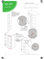
Step 13.
Step 13a.
Insert hanging
bracket into pre-drilled
holes
Step 13b.
Rotate locking
lever 180 degrees
Step 13c.
Secure with provided
2 x 20mm screws (S) per bracket
Step 14.
Secure corner gussets to the bottom left and
right hand side of the wall unit using
4 x 15mm screws (L) per plate.
Step 15.
Drill a small pilot hole through the centre of the corner gussets.
Use this hole at the end of the process to screw through and
into the wall. Cover the screw heads using the cover caps (M)
provided. Screwsforxingtowallsarenotprovidedasthese
vary depending on your wall material and construction.
Ensureappropriatexingsforwallconstructionsareused.
S
S
L
L
M
L
L
For Internal Use: FI.WR.INS.048_WKIN00133_WALL_600_Adj_Cnr_Tall_Rev2.indd
Page 5
WALL UNIT
600 Tall Adjustable Corner
Assembly Guide

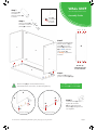
Step 16.
Measure appropriately and attach
the 2 x hanging bracket plates
onto the wall screwing through
the provided holes into your wall.
Screwsforxingtowallsarenot
provided as these vary depending on
your wall material and construction.
Ensureappropriatexingsforwall
construction are used. Hang the
cabinet using the brackets to hook
onto the plate as shown below.
Step 18.
Screw into any side units using the provided 2x 30mm screws (K)
to secure the unit. Screw just to the rear of the hinge plate then
place a cover cap on the head to conceal it.
Step 17a.
Rotate the screw clockwise
to move the cabinet up.
Anti-clockwise for down.
Step 17b.
Adjust the depth
using centre screw.
Step 17c.
Screw the red screw until it
touches the plate to lock
in position.
K
For Internal Use: FI.WR.INS.048_WKIN00133_WALL_600_Adj_Cnr_Tall_Rev2.indd
Page 6
WALL UNIT
600 Tall Adjustable Corner
Assembly Guide

Step 19.
Attach Panel (X) to panel (Y)
usingappropriatexing.
Panels (X) & (Y) can be cut
down to suit the kitchen
requirements.
Step 20.
Attach Panels (X) & (Y)
to the carcass using the
2 x L brackets (R) and the
4 x 15mm screws (L) at the
top and bottom as shown.
Step 21.
Measure and cut down
backing panel to required
size. Attach to carcass using
7 x15mm screws (L), evenly
spaced as shown.
The screws
should be at the
centre of the
carcass panels.
View from inside
R
L
L
L
L
R
X
Y
X
X
Y
Y
L
L
L
Panel X
x1
Panel Y
x1
Adjustable Corner Post Pack
For Internal Use: FI.WR.INS.048_WKIN00133_WALL_600_Adj_Cnr_Tall_Rev2.indd
Page 7
WALL UNIT
600 Tall Adjustable Corner
Assembly Guide

Panel X
x1
Panel Y
x1
Step 22.
Insert hinges in top & bottom
holes as shown.
Step 23.
Secure hinges by tightening
2 x screws with hinge dowels
attached. These are already
positioned within the hinges.
Step 24.
Attach the door to unit
where required.
To attach door
clip hinge onto hinge
plate and click to secure.
Hinges
Hinge Cover Caps
Step 26.
Fit cover caps to hinge.
Step 25.
Adjust hinge to suit. As shown below.
To adjust hinge using a screw
driver, tighten or loosen as
required at points 1 & 2.
Point 1 - left - right
Point 2 - side - side
1
2
FRONTAL HINGE
ADJUSTMENT
Hinge Plates
View from Inside of Carcass
To release door,
pull catch as shown,
to release hinge from
the hinge plate.
For Internal Use: FI.WR.INS.048_WKIN00133_WALL_600_Adj_Cnr_Tall_Rev2.indd
Page 8
WALL UNIT
600 Tall Adjustable Corner
Assembly Guide

WALL UNIT
600 Tall Adjustable Corner
Assembly Guide

WALL UNIT
600 Tall Adjustable Corner
Assembly Guide

-
 1
1
-
 2
2
-
 3
3
-
 4
4
-
 5
5
-
 6
6
-
 7
7
-
 8
8
-
 9
9
-
 10
10
-
 11
11
-
 12
12


in altre lingue
- English: Wren 600
Altri documenti
-
Concepts In Wood SR3084-C Guida d'installazione
-
Edgewater Networks 318CC Owner Assistance Manual
-
Yamaha VX110 Sport Manuale utente
-
Speed Queen Super 20 CL8771 Manuale utente
-
-
-
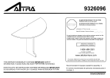 Dorel Home Furnishings 9326096 Manuale del proprietario
-
Southern Enterprises HD9175 Istruzioni per l'uso
-
KYMCO 125 AGILITY CITY Manuale utente
