
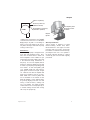
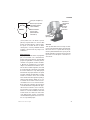
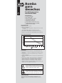
318/320CC
318/320 Center Console
OWNER ASSISTANCE MANUAL
Revised 2015

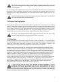
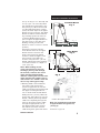
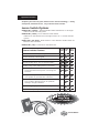
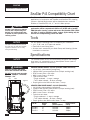
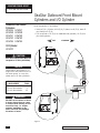
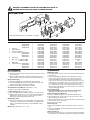
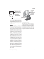
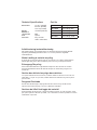
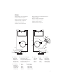
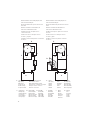
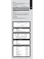
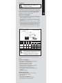
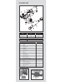
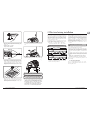
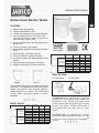
320CC SPECIFICATIONS
LENGTH: 31’10” (9.7m)
BEAM: 10’2” (3.1m)
DRAFT (boat only): 22” (56cm)
BOAT WEIGHT: 6500lbs (2948kg)
WEIGHT CAPACITY: 4300lbs (1950kg)
PERSON CAPACITY: 12
PERSON WEIGHT: 1980lbs (900kg)
FUEL CAPACITY: 300gal (1135.62L)
TRANSOM HEIGHT: Twin-25”
MAX POWER: 700hp (525kw)
COCKPIT DEPTH: 30” (76cm)
COCKPIT AREA: 130sq/ft (12m²)
APPROX LENGTH ON TRAILER: 40’ (12.1m)
BRIDGE CLEARANCE:
W/OUT TOP 6’ 4” (1.8m)
W/T-TOP 9’7” (2.9m)
FLOTATION: UNSINKABLE
HULL DEADRISE: 24°
CE
10 PERSONS OR 1150kg
525kw MAX POWER
B RATING

Dear EdgeWater 3CC Owner:
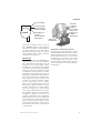
Congratulations on purchasing one of the finest small boats ever built. It has been constructed with
care from the finest available materials. At EdgeWater we take great pride in the quality and
craftsmanship that goes into each boat, large or small. We believe you’ll have many years of
enjoyment from your new EdgeWater and thank you for entrusting your leisure time to one of our fine
products.
This manual has been assembled to help you learn more about your new boat and increase your
enjoyment of it. Your EdgeWater has been built for a “Lifetime on the Water”.
Boat safe and boat smart, we wish you many years of boating pleasure.
Sincerely,
Peter Truslow
President
EdgeWater Powerboats

2
6HUYLFH,QIRUPDWLRQ
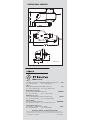
Please fill out the information below completely. It will help us in assisting you in the event your
EdgeWater needs service.
Customer Name ______________________________________________________________________
Address _____________________________________________________________________________
City __________________________________________ State Zip
Phone _________________________Cell _____________________Business _____________________
E-mail Address _______________________________________________________________________
Dealer Name _________________________________________________________________________
Address _____________________________________________________________________________
City ___________________________________________ State ______ Zip ______________
Phone _________________________________________ Fax __________________________________
Purchase Date __________________________________ Engine Make/Model ____________________
Delivery Date ___________________________________ Engine Serial # _________________________
Hull Number __DMA______________________________ Ignition Key # ___________________________
(GJH:DWHU3RZHU%RDWV//&UHVHUYHVWKHULJKWWRPDNHDOWHUDWLRQVLQWKHVWDQGDUGDQG
RSWLRQDOHTXLSPHQWZLWKRXWLQFXUULQJREOLJDWLRQWRWKRVHERDWVDOUHDG\KDYLQJEHHQEXLOW
(YHU\HIIRUWKDVEHHQPDGHWRHQVXUHWKDWWKHLQIRUPDWLRQLQWKLVPDQXDODFFXUDWHO\
GHVFULEHVYHVVHOVEHLQJEXLOWDWWKHGDWHRISULQWLQJ

4
Table of Contents
&KDSWHU*HQHUDO,QIRUPDWLRQ
1.1 General ................................................................................................................................ 6
1.2 Owner / Operator Responsibilities ....................................................................................... 6
&KDSWHU+HOP&RQWURO6\VWHPV
2.1 General ................................................................................................................................ 7
2.2 Steering System ................................................................................................................... 7
2.3 Engine Throttle and Shift Controls ....................................................................................... 7
&KDSWHU3URSXOVLRQ6\VWHP
3.1 General ................................................................................................................................ 8
3.2 Engine Cooling System ........................................................................................................ 9
3.3 Propellers ............................................................................................................................ 9
3.4 Engine Power Tilt and Trim ................................................................................................ 10
3.5 Engine Instrumentation ..................................................................................................... 10
&KDSWHU)XHO6\VWHP
4.1 General .............................................................................................................................. 12
4.2 Fuel Fill .............................................................................................................................. 12
4.3 Fuel Vent ............................................................................................................................ 12
4.4 Fueling ............................................................................................................................... 12
4.5 Fuel System Maintenance ................................................................................................. 13
4.6 Fuel Filters ......................................................................................................................... 13
&KDSWHU(OHFWULFDO6\VWHP
5.1 General .............................................................................................................................. 13
5.2 Accessory Panel Switches ................................................................................................. 13
5.3 Electrical System Maintenance .......................................................................................... 14
&KDSWHU5DZ:DWHU)UHVKZDWHU6\VWHPV
6.1 General .............................................................................................................................. 14
6.2 Livewell Operation ............................................................................................................. 14
6.3 High Pressure Washdown ................................................................................................. 15
6.4 Freshwater System ............................................................................................................ 15
6.5 Water Systems Maintenance ............................................................................................. 15
&KDSWHU'UDLQDJH6\VWHP
7.1 General .............................................................................................................................. 15
7.2 Cockpit Drains .................................................................................................................... 16
7.3 Transom Bilge .................................................................................................................... 16
7.4 Locker Drains .....................................................................................................................16
7.5 Console Bilge......................................................................................................................16

5
&KDSWHU6DIHW\(TXLSPHQW
8.1 Required Safety Equipment .............................................................................................. 17
8.2 Suggested Safety Equipment - Inshore ............................................................................. 18
8.3 Suggested Safety Equipment – Offshore ........................................................................... 18
&KDSWHU6DIH2SHUDWLRQ
9.1 Pre-Cruise Check List ........................................................................................................ 19
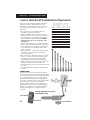
9.2 Basic Rules of the Road .................................................................................................... 20
9.3 Safe Operation ................................................................................................................... 21
9.4 Towing or Being Towed ..................................................................................................... 21
9.5 Stopping the Boat .............................................................................................................. 22
9.6 Docking .............................................................................................................................. 22
9.7 After Operation ................................................................................................................. 22
9.8 Trailering Your Boat ........................................................................................................... 22
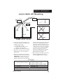
9.9 Launching Your Boat ......................................................................................................... 23
9.10 Retrieving Your Boat ........................................................................................................ 24
&KDSWHU5RXWLQH0DLQWHQDQFH
10.1 Exterior Hull and Deck ..................................................................................................... 24
10.2 Engine .............................................................................................................................. 25
&KDSWHU([WHULRU(TXLSPHQW
11.1 Anchor Locker .................................................................................................................. 26
11.2 Boarding Ladder .............................................................................................................. 26
11.3 Trim Tabs..........................................................................................................................26
&KDSWHU6HDVRQDO0DLQWHQDQFH
12.1 Engine .............................................................................................................................. 27
12.2 Hull ................................................................................................................................... 27
12.3 Storage ............................................................................................................................ 27
12.4 Trailer ............................................................................................................................... 27
$SSHQGL[

6
*HQHUDO,QIRUPDWLRQ
*HQHUDO
Your EdgeWater 3
CC is a semi-custom offshore fishing vessel that is designed to be powered
by dual outboard engine
s.
2ZQHU2SHUDWRU5HVSRQVLELOLWLHV
5HJLVWUDWLRQ
Registering your boat is important to you. Federal Law requires that all powered, undocumented
vessels be registered in their state of principal use. Contact the appropriate agency in your local
state to obtain specific registration information.
5HSRUWLQJ%RDWLQJ$FFLGHQWV
All boating accidents must be reported to the proper authorities in the state that the accident
occurred. If someone dies or disappears as a result of the recreational boating accident, it must
be reported immediately, with a formal report being made within 48 hours. If there is damage of
more than $500, or if the boat is completely lost, a formal report must be made within 10 days.
Questions regarding accidents may be directed to the Boating Safety Hotline, 800-368-5647.
(GXFDWLRQ
Whether or not you are an experienced boater, attending a Boating Education Course can be
beneficial. If you are inexperienced, it is the best, safest way to begin your life on the water. If you
are an experienced boater, it’s always good to sharpen your skills.
5HTXLUHG(TXLSPHQW
The U.S. Coast Guard requires certain equipment on each boat. In addition, they also set
minimum equipment and safety standards. For more detailed requirement information, obtain
“Federal Requirements And Safety Tips For Recreational Boats”, by contacting the Boating Safety
Hotline,
800-368-5647.
6RPHVWDWHVDQGORFDODJHQFLHVUHTXLUHHTXLSPHQWWKDWLVQRWUHTXLUHGE\WKH86&RDVW
*XDUG<RXUORFDODJHQF\RUGHDOHUFDQSURYLGHVSHFLILFLQIRUPDWLRQUHJDUGLQJWKHVHQRQ
VWDQGDUGUHTXLUHPHQWV

7
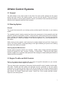
+HOP&RQWURO6\VWHPV
*HQHUDO
The helm station is the control center for the boat. The main control systems are the engine
throttle and shift controls, the steering system, and the trim tab controls. These provide the
operator the ability to control speed, direction, boat trim, and attitude. Each manufacturer provides
manuals on the operation and use of their systems.
6WHHULQJ6\VWHP
*HQHUDO
The manual that comes with your steering system provides specific information on your steering
system.
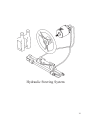
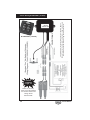
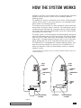
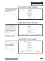
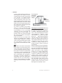
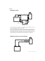
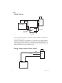
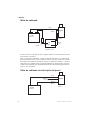
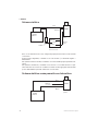
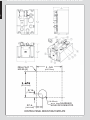
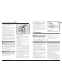
The standard hydraulic steering system has three main components: a helm assembly and dual
hydraulic cylinders connected by a tie-bar. Turning the helm, which pumps fluid into the hydraulic
hoses, activates the hydraulic cylinders and causes the motors to turn. The helm acts as both
pump and reservoir. Please see diagram in the manual’s appendix for a visual representation of
this system.
While running at slow speeds, most boats tend to wander slightly back and forth. Keeping the
wheel in the center without overcompensating for the slight wandering will prevent over steering
and reduce the tendency to wander.
6WHHULQJ6\VWHP0DLQWHQDQFH
Routine system inspection should occur regularly. Cables, hoses, linkage and helm assemblies
should be inspected for wear, corrosion, cracking, or deterioration. Cleaning and light grease
should be applied to all exposed metal parts and other damaged or deteriorated parts should be
replaced as soon as possible
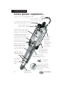
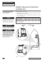
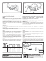
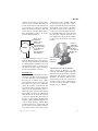
(QJLQH7KURWWOHDQG6KLIW&RQWUROV
Refer to the engine manual supplied with your engine for specific information on your controls.
The ones depicted are those supplied by Yamaha.
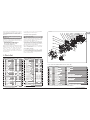
There are three major components of the engine throttle and shift controls: handles, throttle cable,
shift cable. Throttle and shift cables are push-pull and are connected to the fuel system
(carburetor or fuel injection) and the other to the shift rod linkage. By moving the handles forward
and back, the operator engages the cables thus controlling the amount of fuel being used and the
gear selector for forward, neutral and reverse. Careful use of the controls provides smooth,
responsive and safe operation.

8
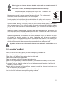
'RQRWEULQJWKHWKURWWOHEDFNDEUXSWO\WRVWRSWKHERDWXQOHVVLWLVDQHPHUJHQF\$OORZ
WLPHIRUWKHHQJLQH530WRFRPHGRZQWRLGOHEHIRUHVKLIWLQJWRUHYHUVHRUVHYHUHJHDUER[
GDPDJH FRXOG RFFXU 3/($6( 5()(5 72 <285 (1*,1( 2:1(5¶6 0$18$/ )25
)857+(523(5$7,21$/352&8'85(6)25<285287%2$5'
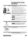
(QJLQH6WRS6ZLWFK
This device is designed to shut down the engine in the event that the operator is thrown away
from the helm station. The operator should always wear the engine stop switch lanyard while the
boat is in motion. Pulling the lanyard from the control will stop the engine. If the engine will not
crank properly, the lanyard may not be properly attached to the engine stop switch.
'RQRWXVH WKH HQJLQH VWRS VZLWFKWRVWRSWKH ERDW XQOHVVLWLVDQ HPHUJHQF\DV LW PD\
LPSDLU\RXUDELOLW\WRTXLFNO\UHVWDUWWKHHQJLQH
127((DFKLJQLWLRQNH\KDVDGLJLWQXPEHUVWDPSHGRQLW3OHDVHUHFRUGWKLVQXPEHU
IRUIXWXUHUHIHUHQFHRQWKHVHUYLFHLQIRUPDWLRQSDJHLQWKHIURQWRIWKLVPDQXDO
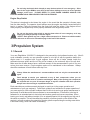
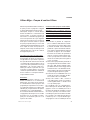
3URSXOVLRQ6\VWHP
*HQHUDO
Your new EdgeWater 3CC is designed to be powered by dual outboard motors only. Most 2-
cycle outboards currently use an automatic system to mix the oil with the gasoline before the
engine uses it. If equipped with 2-cycle engines, there will be oil tanks located inside the
mechanical access space and the oil fills will be located on the motorwell side of the aft deck.
Make sure the oil tanks always have a sufficient amount of the recommended 2-cycle oil for your
cruise, plus some reserve. 4-cycle engines require oil be maintained in the crankcase. Always
check the crankcase oil level before each day’s run.
$OZD\V IROORZ WKH PDQXIDFWXUHU¶V UHFRPPHQGDWLRQV DQG XVH RQO\ WKH UHFRPPHQGHG RLO
W\SHV
'RQ¶W DWWHPSW WR VHUYLFH \RXU RXWERDUGV RU DQ\ RI WKHLU FRPSRQHQWV XQOHVV \RX DUH
WKRURXJKO\IDPLOLDUZLWKLWVRSHUDWLRQDQGGDQJHUV0DQ\RIWKHPRYLQJSDUWFRPSRQHQWV
DUHH[SRVHGDQGFDQSRVHDQH[WUHPHGDQJHUWRDQ\RQHXQIDPLOLDUZLWKWKHLURSHUDWLRQ
$OZD\VOHDYHWKHVHUYLFLQJWRDTXDOLILHGWHFKQLFLDQ
Each manufacturer provides manuals designed to assist you in the proper operation and
maintenance of your new engine(s). Follow their guidance and schedules for proper operation of
your new engine(s). With a modern outboard there is little to do as long as proper maintenance is
performed, in accordance with the manufacturer’s recommendations. If the boat is to be kept in
saltwater for an extended period, electrolysis and marine growth can become a problem. When
leaving your boat in salt water overnight or for an extended period, tilt the engine(s) as high out of
the water as possible. This will decrease the possibility of marine growth on the outside of the
engine(s), as well as reduce the potential of marine growth compromising the cooling water inlets
in the lower unit(s), which can cause overheating.

9
'R QRW SDLQW \RXURXWERDUG¶VORZHUXQLWVZLWK SDLQWV GHVLJQHG IRU ERDWKXOOV 6RPH FDQ
FDXVH VHYHUHGDPDJH WR \RXUHQJLQH &KHFNZLWK\RXUHQJLQH PDQXIDFWXUHU WR JHW WKHLU
UHFRPPHQGDWLRQ
Do not attempt control adjustments unless you are very familiar with their function, operation and
adjustment. Failure to properly adjust the system components can adversely affect your boat’s
performance and safety. Mis-adjustment can also cause severe control, engine or lower unit
damage.
3OHDVHUHWXUQDOOZDUUDQW\FDUGVIRUERDWHQJLQHVDQGRWKHUUHODWHGLWHPV7KLVZLOODVVLVW
\RXLQWKHHYHQW\RXKDYHDZDUUDQW\SUREOHP
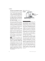
(QJLQH&RROLQJ6\VWHP
Most outboard engines are cooled by water taken in through ports in the lower part of the drive
section. Make sure these ports are free of debris or other items that might cause the flow to be
restricted. Maintain a routine vigilance to see that the visual inspection streams have a steady
flow of water. If they do not, shut down the engine to see if they are clogged or if there is a more
serious problem. Be especially watchful if you have gone through an area of vegetation or
shallow water as the intake ports can become clogged with weeds, dirt or other debris.
'R QRW UXQ \RXU RXWERDUGV ZLWKRXW ZDWHU FRPLQJ LQWR WKH ORZHU XQLW 7KH ZDWHU SXPS
LPSHOOHUVFDQEHGDPDJHGLQRQO\VHFRQGVRIWKLVW\SHRIRSHUDWLRQ
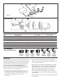
3URSHOOHUV
A turning propeller moves the boat through the water, forward or backward. They should always
be clean and free from nicks or dings, which can adversely affect performance. Your dealer can
assist you in the proper selection of a propeller for your boat. This selection is based on the
horsepower of the engine and its relationship to the size and weight of the boat.
Propeller sizes are determined by two numbers, which appear on different propellers at various
locations. They are listed in sequence, for example 13 x 17. The first number is the diameter of
the propeller and the second is the pitch. Pitch is the theoretical distance the propeller moves
through the water with each complete revolution, the larger the number the greater the theoretical
movement. It also follows that the larger the number the greater horsepower is required to turn it.
With a load which is “normal”, or usual for your boating activities, the engine should be able to
reach its maximum operating RPM range at wide open throttle (WOT). With a light load on
smooth water, the engine should reach its manufacturer’s rated maximum operating RPM at wide-
open throttle (WOT) and maximum trim. If it does not, you may have a propeller that has too
much pitch. If it goes beyond the maximum recommended RPM range, you may have too little
pitch. Neither condition is good for the engine. You will get shorter engine life and poorer
performance than your boat and motor were designed to provide.
,I \RXU ERDW FDPH IURP WKH IDFWRU\ ZLWK D SURSHOOHU VHOHFWHG E\ (GJH:DWHU LW VKRXOG
DOUHDG\ EH RSWLPL]HG IRU WKH SHUIRUPDQFH RI \RXU ERDW %HIRUH FKDQJLQJ WKH SLWFK RU
GLDPHWHURI\RXUSURSHOOHUDOZD\VFKHFNZLWK\RXUGHDOHUWRGHWHUPLQHKRZWKHFKDQJHV
ZLOODIIHFW\RXUERDWDQGHQJLQHSHUIRUPDQFH&HUWDLQPRGLILFDWLRQVVXFKDVERWWRPSDLQWRURSWLRQV
WKDW DIIHFW ZHLJKW EDODQFH DQGRU ZLQG UHVLVWDQFH PD\ ORZHU SHDN USP $OZD\V FKHFN ZLWK \RXU
GHDOHUILUVWLIRSWLPXPUSPFDQQRWEHDWWDLQHG

10
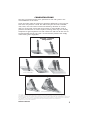
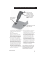
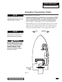
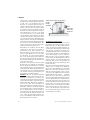
(QJLQH3RZHU7LOWDQG7ULP
The power tilt and trim system on your outboard(s) provides the ability to optimize the running
angle of your EdgeWater 3CC to allow for load and sea conditions. Moving the outboard lower
unit toward the transom is generally referred to as trimming “in”, while moving the outboard lower
unit away from the transom is referred to trimming “out”. It is generally best to have the engine(s)
trimmed in for acceleration from displacement to planning mode. This brings the bow down and
requires less fuel and effort on the engine’s part to plane off the hull.
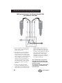
The first 20
o
of movement aft of the transom is referred to as trim and is the area generally used to
operate the boat while on plane. The area beyond the first 20
o
is referred to as tilt and is usually
reserved for operating in shallow water or pulling up on a beach.
While running under normal conditions, the bow should be in a 3
o
to 5
o
up angle to maximize the
hull’s ride and performance. When sea conditions are rougher than normal, bringing the bow
slightly down may improve the ride and will also allow the boat to remain on plane at a lower
speed.
:DWFK WKH KRVHV DQG FDEOHV RQ \RXUHQJLQHV DV WKH\ DUH WLOWHG WR WKHLU IXOO WLOW SRVLWLRQ
7KH\PD\EHFRPHFDXJKWDQGGDPDJHGLIWKHHQJLQHVDUHLQWKHZURQJSRVLWLRQ
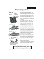
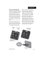
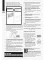
(QJLQH,QVWUXPHQWDWLRQ
The following is presented to familiarize you with the instruments, which may be on your boat.
Every boat is not equipped with full instrumentation.
$OO IDFWRU\ LQVWDOOHG <DPDKD HQJLQHV LQFOXGH <DPDKD¶V GLJLWDO PXOWLIXQFWLRQ WDFKRPHWHU
DQGVSHHGRPHWHU5HIHUWR\RXUHQJLQHRSHUDWRUVPDQXDOIRUXVHGHWDLOV
7DFKRPHWHU
The tachometer displays the number of revolutions per minute (RPM) the engine is turning. There
is a designed operation RPM range for the engine. Become familiar with the operating range of
your engine and its operating characteristics. The tachometers designed to aid the boater to
assure the engine performs within that designed range. The tachometer can be used to better
understand the performance of your engine and your EdgeWater 3CC. By monitoring your
tachometer as you operate your Ed
geWater, you will find RPM ranges that work better in certain
sea and load conditions. Be alert the tachometer operation may provide an early indication of
difficulty, before it becomes irreversible.
6SHHGRPHWHU
The speedometer indicates the boat speed in miles per hour. Some types work using a spinning
wheel to determine the boat speed. Their accuracy can vary from the actual over the bottom
speed due to many factors. Other boat speedometers calculate the speed by amount of pressure
the moving water forces into a “pitot” tube. These gauges should only be used as indicators of
approximate speed and not used as absolute speed indicators. NOTE: All Yamaha
speedometers utilize a pitot tube. In the event that erroneous speed-readings appear, it is likely
caused by debris clogging the pitot tube. Consult with your dealer on methods to clean the tube
and restore normal operation.

11
7HPSHUDWXUH*DXJH
This is designed to monitor the operating temperature of your engine’s cooling system. A sudden
rise from the normal should be investigated to determine if there is an obstruction in the cooling
system.
:DWHU3UHVVXUH*DXJH
This gauge measures pressure in the engine cooling system. If the pressure changes from the
norm it could indicate a complete or partial blockage in the system or a water pump problem. If
this does not return to normal, your dealer should check it to make sure the cooling system is
operating properly. NOTE: Factory rigged boats are not equipped with water pressure gauges.
)XHO*DXJH
This gauge indicates the amount of fuel in the fuel tank. It is always prudent to follow the “rule of
thirds”, one-third of the tank to get the destination, one-third to return, and one-third in reserve.
NOTE: It is important to “calibrate” your fuel gauge during your first initial boat trip. Record the
fuel reading prior to fill up and how may gallons to top off the tank at each fill-up. Make sure the
boat is floating in the same position. By subtracting the amount to top off from total fuel capacity
you can calculate gallons remaining in the tank for 3/4, 1/2, and 1/4 gauge readings.
7KLVJDXJHLVDPHDVXUHRIUHODWLYHIXHOVXSSO\DQGLVQRWDFDOLEUDWHGLQVWUXPHQW
9ROWPHWHU
This meter displays the voltage for the battery and charging system.
+RXU0HWHU
The hour meter keeps a record of operating time and is very useful for scheduling maintenance.
(QJLQH$ODUPV
Most outboards are equipped with several audible engine alarms. Your engine owner’s manual
will familiarize you with these and their sometimes-distinctive sounds.
:DUQLQJ: If an engine alarm sounds, shut down the engine until the source of the problem is
determined.
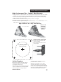
&RPSDVV
The compass assists in determining your location by indicating your position relative to magnetic
north. For accuracy, your compass may need to be adjusted to take into account specifics of your
boat and geographic location. Please refer to the material provided with your compass for
“compensation”.
,QVWUXPHQW0DLQWHQDQFH
Your instrument faces should be periodically cleaned to keep them free of salt and atmospheric
debris. The ignition switches should be periodically sprayed with a contact cleaner/lubricant to
keep them free of corrosion and dirt.

12
)XHO6\VWHP
*HQHUDO
All fuel systems and components on your EdgeWater 3CC have been checked and each fuel
tank has been pressure tested. This inspection and pressure testing assure that your fuel system
is leak proof and safe. It is the purchaser’s responsibility to maintain the fuel system in a safe
manner. Make periodic inspections to determine the system is still safe and free from leaks.
Special care should be taken when inspecting joints and connections to make sure they have not
loosened with vibration.
The EdgeWater fuel system has been designed to meet or exceed the requirements of the U.S.
Coast Guard, the National Marine Manufacturers Association, and the American Boat and Yacht
Council, which were in effect at the time of your boat’s manufacture.
,IDQ\RGRURIJDVROLQHLVGHWHFWHGLPPHGLDWHO\VKXWRIIDOOHQJLQHVDQGHOHFWULFDOGHYLFHV
XQWLOWKHVRXUFHDQGFRQGLWLRQRI WKHRGRUKDV EHHQGHWHUPLQHGDQG HOLPLQDWHG+DYH D
ILUHH[WLQJXLVKHUDWWKHUHDG\XQWLOWKHFRQGLWLRQKDVEHHQUHVROYHG
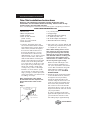
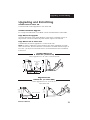
)XHO)LOO
The fuel fill cap is located on the port side and is labeled “GAS”. Turning the cap
“counterclockwise” opens it, and “clockwise” closes it. Tighten the cap until it is snug, not so tight
it cannot be removed at the next fuel stop, or so tight that the rubber o-ring is damaged, allowing
water to enter the system.
)XHO9HQW
This vent is incorporated into the fuel fill cap. This vent allows air to escape from the tank and thus
allows fuel to enter. Make sure the fill and vent area is kept free from debris.
)XHOLQJ
Your EdgeWater 3CC is equipped with a built-in 296 gallon fuel tank. Before fueling, you should
follow these procedures.
·Make sure the boat is securely moored.
·Make sure all switches are off and all cigarettes are extinguished.
·Know the location of all fire extinguishers.
·Remove the fuel fill cap.
·Place the nozzle firm against the side of the opening to prevent static discharge
·Begin fueling.
·When the tank is full stop fueling.
·Re-install the fuel cap.
·Check the area for fuel odors.
:DUQLQJ,IIXHORGRUVDUHGHWHFWHGGRQRWVWDUWWKHHQJLQHV&KHFNWRPDNHFHUWDLQWKHUH
DUHQROHDNVRUV\VWHPSUREOHPVEHIRUHVWDUWLQJWKHHQJLQHV

13
:DUQLQJ'RQRWILOOWKHIXHOWDQNZKLOHWKHHQJLQHVDUHUXQQLQJ'RQRWDOORZVPRNLQJRU
RSHQIODPHVZLWKLQIWRIWKHIXHOLQJDUHD)XHOLVYHU\IODPPDEOH7RSUHYHQWGDPDJHWR
WKH HQJLQHV XVH RQO\ IXHOV ZLWKRXW KDUVK DGGLWLYHV RU DOFRKRO 5HIHU WR \RXU HQJLQH
RZQHU¶VPDQXDOIRUVSHFLILFIXHOUHTXLUHPHQWV
)XHO6\VWHP0DLQWHQDQFH
Regularly inspect the fuel system components. All lines, fittings, and bulbs should be flexible and
not corroded. If fittings or other components are found to have cracks, they should be replaced at
once. If you use your boat infrequently or do not use it for an extended period of time, a fuel
conditioner should be added to a full tank of fuel to prevent fuel deterioration and damage to the
fuel system.
)XHO)LOWHUV
Fuel filters are installed inside the mechanical access space on the forward wall. These are
fuel/water separator type of filters and are designed to prevent water from entering your engine.
The fuel filter element is a spin-off type element. At a minimum, this element should be replaced
at the beginning of every boating season. Always carry a filter wrench and spare filter of the type
supplied on your boat.
(OHFWULFDO6\VWHPV
*HQHUDO
Your EdgeWater 3CC operates on a 12 volt DC system, similar to your automobile. The
batteries, (3 standard, 4 optional), are typically lead acid type and require similar maintenance to
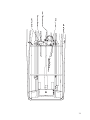
your car’s battery. A standard battery isolator and three batteries are located inside the console,
behind the large door located above the toilet.
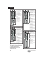
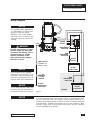
3DQHO6ZLWFKHV
Your EdgeWater 3CC is equipped with panel mounted breakers. Two panels are at the helm
area and o
ne is inside the console. On the 3
CC helms’ main switch panel, switches are
provided for navigation lights, decklights, forward & aft
manual bilge pumps, two for livewells (one
optional), raw and freshwater pumps, fishwell pumpout, spreader lights for t-top (optional), helm &
locker lights, waste discharge, and five accessory switches. A second panel mounted below the
main switch panel includes two ignition switches, engine stop switch, two 12V outlets, battery
parallel switch, along with windlass power and up/down switches.
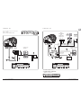
Inside the console, the Master Distribution Panel houses the boats’ battery switches along with
breakers for the “switched” & “un-switched” component mains, electronics main, and anchor
windlass main. Breakers are provided for the following “switched” components: waste & fishwell
pump-outs, anchor windlass, forward and aft bilges, nav/helm/deck/locker lights, raw & freshwater
pumps, livewells, 12V outlets, trim tabs, electric head, stereo, spreader lights, and five
accessories. Breakers for “un-switched” components include: forward & aft auto bilge pumps,
stereo memory, and two spares. Breakers for electronics include radar, GPS, sounder, VHF,
autopilot, displays #1 & 2, one accessory, and eight spares.

14
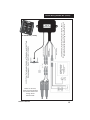
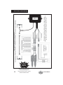
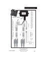
A wiring diagram is included with this manual to assist you in troubleshooting the boat’s electrical
system. Please note that the accessory circuits are each protected by a circuit breaker. Check
that the requirement of any device you install does not exceed the rating of the circuit breaker.
Your 3
CC is equipped with three batteries as standard, designated “PORT ENGINE”, “STBD
ENGI
NE”, and “HOUSE”, with all connected to a battery isolator. The selector switches provide
isolation for each battery and also provide the ability to have a backup in case of a dead or weak
battery, as the batteries are wired in parallel. When in port and running accessories such as
entertainment equipment or pumps, the “HOUSE” battery switch should be set to “ON” and the
“PORT” and “STBD” batteries should be set to “OFF” unless the engines are to be started. When
leaving the boat unattended, all switches should be in the “OFF” position. Current is supplied to
the automatic float switch and the bilge pump even when the battery selector switches are in the
“OFF” position.
(OHFWULFDO6\VWHP0DLQWHQDQFH
At the beginning and end of each season the exposed electrical components of the switch panel
should be sprayed with a non-conductive rust/corrosion inhibiting spray. Light bulb connections
and running light connections should be covered with a non-water soluble lubricant. Care must
be taken not to get grease on the glass portion of the light’s as it will cause them to overheat and
burn out. Inspect all wiring for breaks, loose terminals and sound insulation. Replace worn or
deteriorated components. Check the electrolyte level in the batteries regularly and fill with distilled
water, as necessary. '212729(5),//
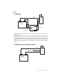
5DZ:DWHU)UHVKZDWHU6\VWHPV
*HQHUDO
Your boat is equipped with fresh and raw water systems. The freshwater components include a
freshwater tank, distribution lines, two sink/shower faucets, and a pump. The standard raw water
system consists of a two high-speed pick-ups located on the transom, three pumps, two washdown
outlets, and one or more livewells.
/LYHZHOO2SHUDWLRQ
Two low maintenance centrifugal pumps located in the mechanical access space fill the
livewell(s). The livewell & accessory livewell switches on the helm switch panel operate the
pumps. In order to properly operate, the valves located behind the access plate at the port aft
corner of the cockpit must be adjusted to provide an even flow in and out of the livewell. Too
much flow and it will be more than the drain can handle, too little and the water will not get proper
circulation. The valve should be turned counterclockwise to open and clockwise to close.
The livewell located at the port aft corner of the boat has a strainer attached to the overboard
drain in order to regulate the height of the water; the center aft livewell has a standpipe strainer
assembly located in the center. The port aft livewell drains through a hose connected to a thru hull
fitting on the port side of the boat, the center aft drains to a starboard side fitting. To completely
drain the port aft livewell remove the bottom plug, and for the center aft livewell remove the

15
standpipe strainer assembly, allowing the water to drain overboard. A diagram of the raw water
system is included with this manual.
+LJK3UHVVXUH:DVKGRZQ
The washdown system is comprised of a pump mounted in the mechanical access space, and
two washdown outlets. The raw water switch on the helm switch panel controls the pump. A
washdown hose bib is located under the forward end of the starboard gunnel board and a
washdown hose and nozzle assembly is located inside the forward anchor locker. These outlets
can be used to wash debris from the boat. The raw water switch should be turned on immediately
prior to use and turned off when not in use. When activated, the pump’s pressure switch will
automatically control the pump. It is normal for the pump to cycle on and off in response to flow
rates and water demand.
$OZD\VWXUQRIIWKHKLJKSUHVVXUHZDVKGRZQSXPSVZLWFKZKHQOHDYLQJWKHERDW
XQDWWHQGHG
)UHVKZDWHU6\VWHP
The freshwater system is comprised of a pump mounted in the mechanical access space and two
showerhead assemblies. The freshwater switch on the helm switch panel controls the pump. A
freshwater tank is located at and filled in the motorwell area of the boat. The fill is located at the
starboard aft transom area on the deck. One showerhead assembly is located in the starboard aft
locker on the deck, the other inside the console at the sink. The freshwater switch should be
turned on immediately prior to use and turned off when not in use. When activated, the pump’s
pressure switch will automatically control the pump. It is normal for the pump to cycle on and off in
response to flow rates and water demand.
$OZD\VWXUQRIIWKHIUHVKZDWHUSXPSVZLWFKZKHQOHDYLQJWKHERDWXQDWWHQGHG
5DZ:DWHU6\VWHP0DLQWHQDQFH
The following checks should be made periodically to assure your system operates properly:
· Periodically spray pumps with a protective silicone solvent to reduce corrosion.
· In-line filters should be cleaned periodically to remove any collected debris.
· Fishboxes and livewells should be drained and cleaned after each use.
· Hoses and connections should be checked periodically for signs of deterioration.
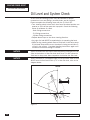
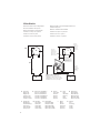
'UDLQDJH6\VWHP
*HQHUDO
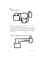
All water drains from your EdgeWater 3
CC by gravity. Your boat is self-bailing at rest and it is
important to
check all drains frequently to make sure they are clear and free flowing. Review the
schematic in the Appendix and become familiar with the location of each thru-hull drain.

16
&RFNSLW'UDLQV
Your EdgeWater 3CC drains through four cockpit drains located at the aft deck area. The deck
is designed to take water and drain it overboard. When washing the boat down after use, use a
hose nozzle with a high-pressure stream to make sure they are clear of debris and free running.
7UDQVRP%LOJH
Your EdgeWater 3CC’s transom bilge is located in the mechanical access space. The aft bilge
system is designed with an external float that automatically turns the pump on if the water in the
bilge rises, or the aft bilge switch on the helm switch panel may also activate it. This pump should
be periodically checked to make sure it is working properly and that the drain screen is clear. To
check the pump, squeeze the pump sides and lift it from the base, which is fastened to the hull.
The screen will be easily seen and if there is debris, it may be cleaned and replaced. Replace the
pump assembly and check its operation by turning on the momentary switch on the helm switch
panel.
When the boat is out of the water, unscrewing the garboard nut located at the bottom of the
transom drains it. This may be removed with a ½” wrench. This plug should be periodically
checked for tightness.
1RWH7KHELOJHVXPSDUHDVKRXOGEHFKHFNHGIRURLOEHIRUHRSHUDWLQJWKHELOJHSXPS7KH
GLVFKDUJH RI RLO IURP D ELOJH DUHD LV LOOHJDO DQG LV VXEMHFW WR D ILQH 7KH )HGHUDO :DWHU
3ROOXWLRQ&RQWURO$FWSURKLELWVWKHGLVFKDUJHRIRLORURLO\ZDVWHLQWRRUXSRQWKHQDYLJDEOH
ZDWHUVRIWKH8QLWHG6WDWHVRUWKHZDWHUVRIWKHFRQWLJXRXV]RQHLIVXFKGLVFKDUJHFDXVHVDILOPRU
VKHHQXSRQRUDGLVFRORUDWLRQRIWKHVXUIDFHRIWKHZDWHURUFDXVHVDVOXGJHRUHPXOVLRQEHQHDWK
WKHVXUIDFHRIWKHZDWHU9LRODWRUVDUHVXEMHFWWRDSHQDOW\RI
/RFNHU'UDLQV
On the 3CC there is a forward anchor locker that drains directly through the hull. The bow
storage lockers located forward drain onto the deck. The lockable rod boxes located beside the
console are drained aft onto the deck. The forward fishbox is drained to a macerator pump which
is controlled by the fishbox pumpout switch on the helm switch panel, and an overboard discharge
valve located in the console bilge. A diagram of the raw water system is included in the Appendix.
&RQVROH%LOJH
Your EdgeWater 3CC has a console bilge where an automatic sump pump and two overboard
discharge valves (holding tank and fishbox drain) are located. The forward bilge switch on the
helm switch panel also controls the sump. Access to the sump and valves is through an access
door located on the lower aft wall inside the console. The sump pump is designed with an internal
float so that it automatically turns on if the water in the sump rises. This pump should be
periodically checked to make sure it is working properly and that the drain screen is clear. To
check the pump, remove the top cover and lift it from the base, which is fastened to the hull. The
screen will be easily seen and if there is debris, it may be cleaned and replaced. Replace the top
cover and check its operation by pouring water into the console drain. Once the water level is high
enough, the pump will automatically turn on and drain the sump.

17
6DIHW\(TXLSPHQW
5HTXLUHG6DIHW\(TXLSPHQW
Contact the U.S. Coast Guard Boating Safety Hotline at 1-800-368-5647, or 1-202-267-1070 to
obtain a pamphlet on the latest required and suggested safety equipment. The Coast Guard
Auxiliary also offers “Courtesy Examinations” to help ensure your boat is properly equipped.
The following is a list of required safety equipment to be aboard your boat. This may be modified
from time to time and it is suggested that you contact the U.S. Coast Guard Boating Safety
Hotline at 800-368-5647 or pick up a copy of the latest “Federal Requirements and Safety Tips of
Recreational Boats” pamphlet.
3HUVRQDO)ORDWDWLRQ'HYLFHV3)'¶V
These must bear a tag that they have been approved by the U.S. Coast Guard and must be in
serviceable condition. They must also be of the appropriate size for the wearer, i.e. for children
there must be children’s life vests on board. Many states now require children to wear PFD’s at all
times. You should check with your state to determine the proper requirements. You should
maintain at least one Type I, II, or III PFD for each person on board, plus one throwable device, a
ring or boat cushion, Type IV.
9LVXDO'LVWUHVV6LJQDOV
These are now required in virtually all waters of the United States. If in doubt, please check with
the U.S. Coast Guard Boating Safety Hotline at 1-800-368-5647 for a specific answer.
3\URWHFKQLF9LVXDO'LVWUHVV6LJQDOV
These must be U.S. Coast Guard approved, be in a serviceable condition, and be readily
accessible. They each have a service life date and are not counted beyond this date. These types
include both hand held flares and aerial flares.
6RXQG6LJQDOLQJ'HYLFH
You must have an efficient means of making a proper sound signal in the event of distress or
poor visibility. This may be a horn, whistle, or bell.
1DYLJDWLRQ/LJKWV
These come with your EdgeWater and meet U.S. Coast Guard requirements. It is important that
you periodically check to make sure they are in working order. It is very important these be
checked prior to any cruise that will keep you on the water after dark.
)LUH([WLQJXLVKHU
A fire extinguisher is standard on all EdgeWater boats. These require regular inspection to
make certain they are ready for use. Questions may be directed to the U.S. Coast Guard Boating
Safety Hotline at 1-800-368-5647, or 1-202-267-1070. You should, as part of routine boat
maintenance; check to make sure your extinguisher is still operable.
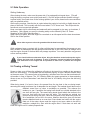
1HYHU GLVFKDUJH \RXU ILUH H[WLQJXLVKHU WR VHH LI LW VWLOO ZRUNV 7KLV ZLOO FDXVH LW WR ORVH
SUHVVXUH,ILWLVDFFLGHQWDOO\GLVFKDUJHGRULILWLVXVHGRQDILUHUHSODFHLWLPPHGLDWHO\

18
6XJJHVWHG6DIHW\(TXLSPHQW,QVKRUH
Suggested safety equipment, over and above the required equipment is:
ҏҏFirst aid kit and manual
ҏҏBoat hook
ҏҏTool kit
ҏҏAn adequate number and size of line should be on the boat. Bowlines should be at least 1/3
longer than the boat’s length and stern lines at least as long as the boat. When operating in areas
with unusually high tidal range, this should be lengthened. The minimum size line for a small boat
is 3/8” diameter 3-strand nylon. Refer to one of the listed references in the Appendix for a
complete discussion on line size relative to boat length.
ҏҏWaterproof flashlight, with good batteries
ҏҏSpare batteries
ҏҏSpare boat keys
ҏҏBinoculars
ҏҏTow line. This should be a minimum of 50’ long with at least one size increase over the boat’s
mooring lines.
ҏҏDay/Night visual distress signals
ҏҏLocal charts and compass
ҏҏProperly sized anchor and line
ҏҏFenders of the proper size
$OZD\VFDUU\ZDWHUHYHQIRUDPLQXWHFUXLVH
6XJJHVWHG6DIHW\(TXLSPHQW±2IIVKRUH
In addition to the required equipment, and the suggested inshore equipment, there is additional
equipment that is prudent to have when venturing offshore. No matter what the conditions at the
start of the trip, the situation can change rapidly and all your equipment and skill can be required
to safely bring your crew home to safety.
ҏҏVHF radio
ҏҏA supplemental, portable VHF is also a good backup
ҏҏSunscreen
ҏҏSpare propeller and the knowledge of how to properly change it, if required
ҏҏExtra clothing for changeable weather conditions
ҏҏSpare anchor with sufficient line for the water depth
ҏҏMirror
ҏҏCharts

19
6DIH2SHUDWLRQ
3UH&UXLVH&KHFN/LVW
ҏҏCheck provisions. Make sure you have plenty of water in the event you have a problem and are
delayed.
ҏҏCheck the weather forecast. Avoid sea conditions that are beyond the experience of yourself and
your crew.
ҏҏDo you have the correct safety gear aboard and is it in good working order?
ҏҏMake sure all fire extinguishers are in good working order.
ҏҏIt is advisable to carry jackets or foul weather gear in the event of adverse weather conditions.
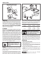
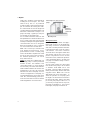
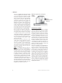
Your EdgeWater 3
CC is equipped with a maximum capacity rating plate permanently affixed to
the helm area of your boat. It will provide information regarding the maximum number of people
you can safely have aboard, the maximum amount of weight the boat can safely carry, and the
maximum horsepower your boat was designed to handle.
'R1RWRYHUORDG\RXUERDW
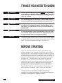
%HIRUH6WDUWLQJWKH(QJLQH
Determine if the trip can be safely made by checking the weather.
Are all the proper boat and personal documents on board?
Check operational equipment, such as running lights and horns to make sure they are on board,
and operable.
Make sure there are enough provisions for the cruise.
Leave a float plan with someone who can notify authorities in the event you do not return in the
allotted time.
Double check the fuel and engine oil levels.
Set the battery switches to “ON”.
Check the emergency stop lanyard to see if it is properly attached, and that the shift lever is in the
neutral position.
5HPHPEHUWKHUXOHRIWKLUGVRXWEDFNDQGLQUHVHUYH
$IWHU6WDUWLQJWKH(QJLQH
Upon initial start-up, make sure to follow the manufacturer’s recommendations for engine break-in
Check to be sure there is a telltale water stream exiting the engine.
Check the gauges to determine if everything is nominal.
Check to make sure everything is secured and properly stowed away; remember the boat’s
movement is dynamic and anything that is loose will become a hazard at the worst possible time.
5HPHPEHUWKDWWKHFDSWDLQLVUHVSRQVLEOHIRUWKHVDIHW\RIWKHFUHZDQGSDVVHQJHUVDQG
IRUKLVKHUERDWVZDNHGDPDJH
1HYHURSHUDWHWKHERDWZKLOHXQGHUWKHLQIOXHQFHRIDOFRKRO
La pagina si sta caricando...
La pagina si sta caricando...
La pagina si sta caricando...
La pagina si sta caricando...
La pagina si sta caricando...
La pagina si sta caricando...
La pagina si sta caricando...
La pagina si sta caricando...
La pagina si sta caricando...
La pagina si sta caricando...
La pagina si sta caricando...
La pagina si sta caricando...
La pagina si sta caricando...
La pagina si sta caricando...
La pagina si sta caricando...
La pagina si sta caricando...
La pagina si sta caricando...
La pagina si sta caricando...
La pagina si sta caricando...
La pagina si sta caricando...
La pagina si sta caricando...
La pagina si sta caricando...
La pagina si sta caricando...
La pagina si sta caricando...
La pagina si sta caricando...
La pagina si sta caricando...
La pagina si sta caricando...
La pagina si sta caricando...
La pagina si sta caricando...
La pagina si sta caricando...
La pagina si sta caricando...
La pagina si sta caricando...
La pagina si sta caricando...
La pagina si sta caricando...
La pagina si sta caricando...
La pagina si sta caricando...
La pagina si sta caricando...
La pagina si sta caricando...
La pagina si sta caricando...
La pagina si sta caricando...
La pagina si sta caricando...
La pagina si sta caricando...
La pagina si sta caricando...
La pagina si sta caricando...
La pagina si sta caricando...
La pagina si sta caricando...
La pagina si sta caricando...
La pagina si sta caricando...
La pagina si sta caricando...
La pagina si sta caricando...
La pagina si sta caricando...
La pagina si sta caricando...
La pagina si sta caricando...
La pagina si sta caricando...
La pagina si sta caricando...
La pagina si sta caricando...
La pagina si sta caricando...
La pagina si sta caricando...
La pagina si sta caricando...
La pagina si sta caricando...
La pagina si sta caricando...
La pagina si sta caricando...
La pagina si sta caricando...
La pagina si sta caricando...
La pagina si sta caricando...
La pagina si sta caricando...
La pagina si sta caricando...
La pagina si sta caricando...
La pagina si sta caricando...
La pagina si sta caricando...
La pagina si sta caricando...
La pagina si sta caricando...
La pagina si sta caricando...
La pagina si sta caricando...
La pagina si sta caricando...
La pagina si sta caricando...
La pagina si sta caricando...
La pagina si sta caricando...
La pagina si sta caricando...
La pagina si sta caricando...
La pagina si sta caricando...
La pagina si sta caricando...
La pagina si sta caricando...
La pagina si sta caricando...
La pagina si sta caricando...
La pagina si sta caricando...
La pagina si sta caricando...
La pagina si sta caricando...
La pagina si sta caricando...
La pagina si sta caricando...
La pagina si sta caricando...
La pagina si sta caricando...
La pagina si sta caricando...
La pagina si sta caricando...
La pagina si sta caricando...
La pagina si sta caricando...
La pagina si sta caricando...
La pagina si sta caricando...
La pagina si sta caricando...
La pagina si sta caricando...
La pagina si sta caricando...
La pagina si sta caricando...
La pagina si sta caricando...
La pagina si sta caricando...
La pagina si sta caricando...
La pagina si sta caricando...
La pagina si sta caricando...
La pagina si sta caricando...
La pagina si sta caricando...
La pagina si sta caricando...
La pagina si sta caricando...
La pagina si sta caricando...
La pagina si sta caricando...
La pagina si sta caricando...
La pagina si sta caricando...
La pagina si sta caricando...
La pagina si sta caricando...
La pagina si sta caricando...
La pagina si sta caricando...
La pagina si sta caricando...
La pagina si sta caricando...
La pagina si sta caricando...
La pagina si sta caricando...
La pagina si sta caricando...
La pagina si sta caricando...
La pagina si sta caricando...
La pagina si sta caricando...
La pagina si sta caricando...
La pagina si sta caricando...
La pagina si sta caricando...
La pagina si sta caricando...
La pagina si sta caricando...
La pagina si sta caricando...
La pagina si sta caricando...
La pagina si sta caricando...
La pagina si sta caricando...
La pagina si sta caricando...
La pagina si sta caricando...
La pagina si sta caricando...
La pagina si sta caricando...
La pagina si sta caricando...
La pagina si sta caricando...
La pagina si sta caricando...
La pagina si sta caricando...
La pagina si sta caricando...
La pagina si sta caricando...
La pagina si sta caricando...
La pagina si sta caricando...
La pagina si sta caricando...
La pagina si sta caricando...
La pagina si sta caricando...
La pagina si sta caricando...
La pagina si sta caricando...
La pagina si sta caricando...
La pagina si sta caricando...
La pagina si sta caricando...
La pagina si sta caricando...
La pagina si sta caricando...
La pagina si sta caricando...
La pagina si sta caricando...
La pagina si sta caricando...
La pagina si sta caricando...
La pagina si sta caricando...
La pagina si sta caricando...
La pagina si sta caricando...
La pagina si sta caricando...
La pagina si sta caricando...
La pagina si sta caricando...
La pagina si sta caricando...
La pagina si sta caricando...
La pagina si sta caricando...
La pagina si sta caricando...
La pagina si sta caricando...
La pagina si sta caricando...
La pagina si sta caricando...
La pagina si sta caricando...
La pagina si sta caricando...
La pagina si sta caricando...
La pagina si sta caricando...
La pagina si sta caricando...
La pagina si sta caricando...
La pagina si sta caricando...
La pagina si sta caricando...
La pagina si sta caricando...
La pagina si sta caricando...
La pagina si sta caricando...
La pagina si sta caricando...
La pagina si sta caricando...
La pagina si sta caricando...
La pagina si sta caricando...
La pagina si sta caricando...
La pagina si sta caricando...
La pagina si sta caricando...
-
 1
1
-
 2
2
-
 3
3
-
 4
4
-
 5
5
-
 6
6
-
 7
7
-
 8
8
-
 9
9
-
 10
10
-
 11
11
-
 12
12
-
 13
13
-
 14
14
-
 15
15
-
 16
16
-
 17
17
-
 18
18
-
 19
19
-
 20
20
-
 21
21
-
 22
22
-
 23
23
-
 24
24
-
 25
25
-
 26
26
-
 27
27
-
 28
28
-
 29
29
-
 30
30
-
 31
31
-
 32
32
-
 33
33
-
 34
34
-
 35
35
-
 36
36
-
 37
37
-
 38
38
-
 39
39
-
 40
40
-
 41
41
-
 42
42
-
 43
43
-
 44
44
-
 45
45
-
 46
46
-
 47
47
-
 48
48
-
 49
49
-
 50
50
-
 51
51
-
 52
52
-
 53
53
-
 54
54
-
 55
55
-
 56
56
-
 57
57
-
 58
58
-
 59
59
-
 60
60
-
 61
61
-
 62
62
-
 63
63
-
 64
64
-
 65
65
-
 66
66
-
 67
67
-
 68
68
-
 69
69
-
 70
70
-
 71
71
-
 72
72
-
 73
73
-
 74
74
-
 75
75
-
 76
76
-
 77
77
-
 78
78
-
 79
79
-
 80
80
-
 81
81
-
 82
82
-
 83
83
-
 84
84
-
 85
85
-
 86
86
-
 87
87
-
 88
88
-
 89
89
-
 90
90
-
 91
91
-
 92
92
-
 93
93
-
 94
94
-
 95
95
-
 96
96
-
 97
97
-
 98
98
-
 99
99
-
 100
100
-
 101
101
-
 102
102
-
 103
103
-
 104
104
-
 105
105
-
 106
106
-
 107
107
-
 108
108
-
 109
109
-
 110
110
-
 111
111
-
 112
112
-
 113
113
-
 114
114
-
 115
115
-
 116
116
-
 117
117
-
 118
118
-
 119
119
-
 120
120
-
 121
121
-
 122
122
-
 123
123
-
 124
124
-
 125
125
-
 126
126
-
 127
127
-
 128
128
-
 129
129
-
 130
130
-
 131
131
-
 132
132
-
 133
133
-
 134
134
-
 135
135
-
 136
136
-
 137
137
-
 138
138
-
 139
139
-
 140
140
-
 141
141
-
 142
142
-
 143
143
-
 144
144
-
 145
145
-
 146
146
-
 147
147
-
 148
148
-
 149
149
-
 150
150
-
 151
151
-
 152
152
-
 153
153
-
 154
154
-
 155
155
-
 156
156
-
 157
157
-
 158
158
-
 159
159
-
 160
160
-
 161
161
-
 162
162
-
 163
163
-
 164
164
-
 165
165
-
 166
166
-
 167
167
-
 168
168
-
 169
169
-
 170
170
-
 171
171
-
 172
172
-
 173
173
-
 174
174
-
 175
175
-
 176
176
-
 177
177
-
 178
178
-
 179
179
-
 180
180
-
 181
181
-
 182
182
-
 183
183
-
 184
184
-
 185
185
-
 186
186
-
 187
187
-
 188
188
-
 189
189
-
 190
190
-
 191
191
-
 192
192
-
 193
193
-
 194
194
-
 195
195
-
 196
196
-
 197
197
-
 198
198
-
 199
199
-
 200
200
-
 201
201
-
 202
202
-
 203
203
-
 204
204
-
 205
205
-
 206
206
-
 207
207
-
 208
208
-
 209
209
-
 210
210
-
 211
211
-
 212
212
-
 213
213


Edgewater Networks 318CC Owner Assistance Manual
- Tipo
- Owner Assistance Manual
- Questo manuale è adatto anche per
in altre lingue
- English: Edgewater Networks 318CC
Documenti correlati
Altri documenti
-
Franke KBX16045-20RDP Scheda dati
-
Boston Whaler 280 Outrage Manuale del proprietario
-
-
JABSCO 50890 Manuale utente
-
 SPX FLOW Ultima Bilge 1250GPH Manuale utente
-
 JOHNSON PUMP - SPX FLOW 36152 Manuale utente
-
-
Kohler KD625-3 Manuale utente
-
-
Makita SP252-4R Manuale del proprietario

