Elvox 6931 Istruzioni per l'uso
- Categoria
- Impianti citofonici
- Tipo
- Istruzioni per l'uso

Installation and operation manual
Art. 6931
Audio speech unit “Due Fili Elvox”

2
GB
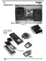
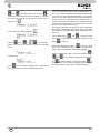
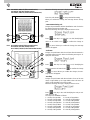
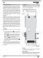
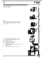
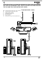
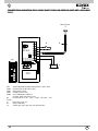
The expansion modules (type 12TS, 12TS/0, 693p, 8051, 8052, 8053,
8054) can be connected to speech unit type 6931 to increase the num-
ber of the call push-buttons according to the type of panel.
12TS Additional module with 4 call push-buttons to install in panels
series 1200.
12TS/0 Additional module for connecting 8 push-buttons, applicable
also to entrance panels not belonging to the Elvox series.
693P Addition module with reduced dimensions: 48x70x19 mm (W
x H x D), to be applied also to non ELVOX entrance panels.
8054 (8051, 8052, 8053) additional modules with 4, 1, 2, 3 call
push-buttons with plates, for entrance panels series 8000.
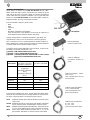
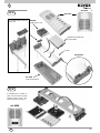
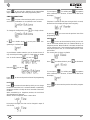
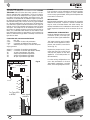
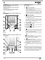
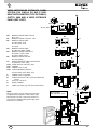
Cable for additional
push-button modules to
CN10
Cable for “Engaged – Please
wait” to C3.3
(Two coloured wires: one red
and one black)
Cable for two push-buttons
to C 3.4 - CH1
to C 3.2 - CH2
((Two coloured green wires)
Cable for name-tag lighting
a C3.6 - Name-tag led
(Two coloured wires: one
green and one black)
Microphone
C3.2 - C3.4
Bracket with fi xing
screws for speech unit
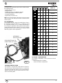
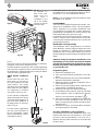
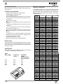
GENERAL INFORMATION
Article 6931 is a speech unit for DUE FILI ELVOX “ELVOX TWO-
WIRE” audio door entry systems. Article 6931 can manage up to 200
calls and can be used as a Master speech unit, making it possible to
create audio door entry systems. In addition, it can co-exist with video
panels in a mixed DUE FILI ELVOX “ELVOX TWO-WIRE” system (in-
terphone/monitor), by using concentrators art. 692C.
It can be installed in entrance panels series:
- 8000
- 8100
- Patavium
- 3300
- Mail boxes (2550/301 and 2550/302)
- 1200 (for more than 2 push-buttons it is necessary to couple one or
more additional plates with push-buttons type 125x).
Speech unit type 6931 is completely equivalent to type 6930. The
only difference is that, in case of connection of camera type 6570,
657C or interface for TVCC camera type 693T it enables a higher di-
stance between the speech unit and the camera (see wiring diagrams
N. SI559, SI560 for the maximum length of wiring).
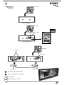
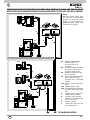
Type 6931 can be coupled with B/W or colour cameras, or with conver-
ter module for external camera type CCTV.
Type 6570 B/W camera without speech unit
Type 657C Colour camera without speech unit
Type 693T Converter module for external B/W or colour camera
(type CCTV) in 4 DIN modules enclosure.
Series of en-
trance panels
With internal camera
type 6931 + type 6570
type 6931 + type 657C
With external camera
type 6931 + type 693T
8000 YES
by applying
type 8010 + 8020 (for
6570)
type 8010 + 8T20 (for
657C)
YES
8100 NO YES
PATAVIUM NO YES
3300 NO YES
2550/301-302 YES YES
1200 NO YES

GB
3
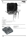
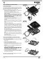
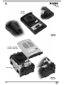
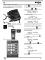
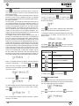
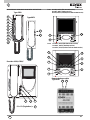
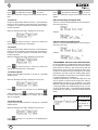
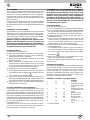
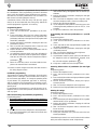
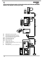
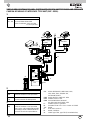
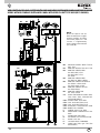
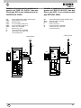
Fig. 1
C3.1 Microphone
Speech unit adjustments
External volume
Speech unit activation time
Internal volume
The settings are printed on the back of the speech unit (see Fig. 1)
M
VL
CN10
C B A
CN9
Connector
for
Art. 950C or
Art. 692I or
Art. 692I/U
M
CA
B2 B1 S-
S+
C3.5 Video
C3.2- CH2
C3.3 Wait/busy
C3.4 - CH1
C3.6 Internal LED power supply
RESET
Speech unit terminals
M VL GROUND
VL POWER SUPPLY OF LEDS FOR SUPPLEMENTARY MODULES
M GROUND
CA DOOR LOCK COMMAND (CONNECT TO “M”)
B2 2-WIRE BUS
B1 2-WIRE BUS
S- LOCK OUTPUT
S+ LOCK OUTPUT
The speech unit gives a current peak IT> 1A for 10 mS after which there follows a holding current I
M
= 200mA for the entire
duration of the lock command (see lock time).
LED supply
voltage for
additional
modules
C3.2- C3.4

4
GB
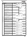
Series of
entrance pa-
nels
Number of
push-buttons
Entrance panel type Cables Substitutive
lamp holder
type
Figure
8000
1 88T1 C3.4, C3.6 Fig. 5, page 10
1 8911 C3.4, C3.6 R263 Fig. 6, page 10
2 88T2 C3.2, C3.4, C3.6 Fig. 5, page 10
2 891D C3.2, C3.4, C3.6 R263 Fig. 6, page 10
More than 2
push-buttons
80PA + 8054 (o 8051,
8052, 8053) + module
holder frames, boxes se-
ries 8000
CN10, C3.3 Fig. 4B, page 9
More than 2
push-buttons
RPF3 + 8054 (o 8051,
8052, 8053) + module
holder frames, boxes se-
ries 8000
CN10 Fig. 4A, page 9
8100
1 8101 C3.4, C3.6 Fig. 8, page 12
2 8102 C3.2, C3.4, C3.6 Fig. 8, page 12
PATAVIUM
1 2101 C3.4, C3.6 Fig. 9, page 12
2 2102 C3.2, C3.4, C3.6 Fig. 9, page 12
More than 2
push-buttons
21xx + 693P C3.6, CN10
3300
1 3301 + Back box Serie
3300
C3.4, C3.6 R261 Fig. 11, page 13
2 3302 + Back box Serie
3300
C3.2, C3.4, C3.6 R261 Fig. 11, page 13
More than 2
push-buttons
3300 + 3958 + Back box
Serie 3300
CN10
330X + 39xx + Back box
Serie 3300
C3.6, CN10
2550/301-302
1 2550/301 C3.4, C3.6 R261 Fig. 10, page 13
2 2550/302 C3.2, C3.4, C3.6 R261 Fig. 10, page 13
1200
1 1200 C3.4, C3.6 R264 Fig. 7, page 11
2 1200 C3.2, C3.6, C3.4 R264 Fig. 7, page 11
1200 with
more than 2
calls
1200 (only for speech unit
Art. 6931) + 125x + 12TS
CN10, C3.6 R264 Fig. 7, page 11
Cabinet
1 25V2* C3.4, C3.6 R264 Fig. 13, page 14
2 25V2 C3.2, C3.4, C3.6 R264 Fig. 13, page 14
Up to 8 pu-
sh-buttons
25V4 or 25V6 or 25V8,
693P
C3.6 R264 Fig. 13, page 14
Up to 12 pu-
sh-buttons
25V8, 2508, 2x693P C3.6, C3.10 R264 Fig. 13, page 14
Up to 24 pu-
sh-buttons
25V8, 2526, 693P,
2x693P
CN10 and cable of
art. 693P and art.
693P/M
R264 Fig. 13, page 14

GB
5
C
B
A
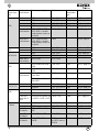
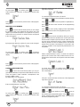
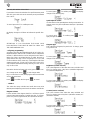
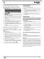
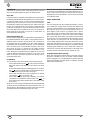
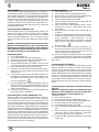
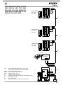
Fig. 2
CN9
ON
123
4
ON
123
4
ON
123
4
ON
123
4
ON
123
4
ON
123
4
ON
123
4
ON
123
4
ON
123
4
ON
123
4
ON
123
4
ON
123
4
ON
123
4
ON
123
4
ON
123
4
ON
123
4
1234
DIP SWITCH
ID TARGA
ON
ON
ON ON
ON
ON ON
ON ON
ON ON ON
ON
ON ON
ONON
ON ON ON
ON ON
ON ONON
ON ONON
NON ASSEGNATO
1 (MASTER)
2
3
4
5
6
7
8
9
10
11
12
13
14
15ON ONONON
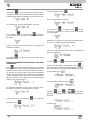
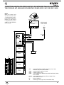
SOFTWARE CONFIGURATIONS
The software confi gurations can be carried out in two dif-
ferent ways:
- basic confi guration of software
- advanced software confi gurations
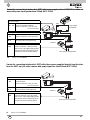
INSTALLATION
Assembling and installing the speech unit Art. 6931 requires
the following phases:
- installing the speech unit
- wiring the leads
- installing and wiring any additional modules
- connecting the speech unit to the system
- assigning identifi cation
- programming the speech unit
N.B. Do not connect the bus of the speech unit to the system
until the speech unit wirings have been connected to the
entrance panel.
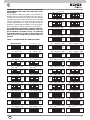
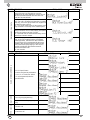
BUS TERMINATION
On the bottom left side, above the terminal block, there is
the 3-position connector CN9 (Fig. 2). A jumper in one of
the 3 possible positions (A, B, C) enables terminating the
bus correctly as regards the video signal for mixed systems
(audio and video door entry systems). Try out the condition
providing the best vision. If the system is solely an audio
door entry system, insert it in position A.
ASSIGNING
IDENTIFICATION
CN10 ADDITIONAL PU-
SHBUTTONS ART. 8054
ASSIGNING IDENTIFICATION
The identifi er is assigned with 4 dip switches on the bot-
tom left side above the terminal block (Fig. 2), outside the
enclosure and under the safety lid. The correspondence
between the position of the dip switch and the ID is speci-
fi ed in the following table.
MICROPHONE
ENTRANCE
PANEL ID
NOT ASSIGNED

6
GB
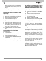
Fig. 3A
1
1
2
2
2
Fig. 3B
3
4
2
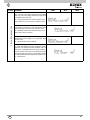
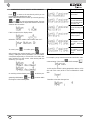
RESETTING PROGRAMS TO THE DEFAULT VALUE
It is possible to bring the programs back to the default value
with a straightforward procedure.
• Open the speech unit by levering on the fastener hooks
(see Fig. 4A).
• Raise the fastener labelled 1 (up arrow).
• Raise the fastener labelled 2 (up arrow).
• Momentarily move the jumper of the termination from CN9
onto terminals 2 and 3 of the programming connector (see
Fig. 4B).
• Momentarily press the reset button RST with the aid, if ne-
cessary, of a plastic screwdriver.
DO NOT USE ANY METAL INSTRUMENTS THAT CAN
MECHANICALLY DAMAGE THE ELECTRONIC CIR-
CUIT OR CREATE SHORT CIRCUITING.
• The speech unit emits a continuous tone for two seconds.
• As the tone is being emitted, press one of the call buttons.
The programs are now reset.
The speech unit restarts by itself. Afterwards put the jumper
back into its original position CN9.
BASIC SOFTWARE CONFIGURATIONS
PUSH-BUTTONS RESET
For the outdoor station it is possible to reset the two push-but-
tons CH1 and CH2 without using external helps. This can be
done with the following procedure, described for a generic pu-
sh-button. It is applied either to CH1 either to CH2.
- Remove the terminal block protection cover prizing up on
the closing hooks (see fi g. 3A, arrow 1).
- Raise the hooks indicated with 1 (arrow upward)
- Hold down the RESET push-button using, if necessary, a
plastic screwdriver.
DO NOT USE METALLIC INSTRUMENTS WHICH CAN
DAMAGE MECHANICALLY THE ELECTRONIC CIRCUIT
OR CAUSE SHORT-CIRCUITS.
- Holding down the RESET push-button, keep pressed also
the call push-button to be reprogrammed.
- Hold down the call push-button, release the RESET pu-
sh-button.
- After two seconds the loudspeaker emits a tone. Simulta-
neously all the sets with the hook lifted emit a three tone
scale.
- Release the call push-button.
- Press, from the internal unit you want to call with the pu-
sh-button, one of the push-buttons: lock release, actuator
activation, stair light, F1, F2. Pay attention that if you want
to call a group, this manoeuvre is to be effected by the
leader of the group. You have 25 seconds to carry out this
operation, after that the outdoor station goes back to the
rest mode emitting a tone.
- The outdoor unit confi rms the programming with a tone.
- To return to default programming, instead of acting on the
internal unit, press again the push-button you want to pro-
gram.
- As an option, verify if the association is correct by pressing
the just programmed push-button and control if the desired
internal unit is called.
- At the end fi t the protection cover again.
Fig. 3C

GB
7
ON
123
16
8
4
ON
123
128
64
32
ON
123
16
8
4
ON
123
128
64
32
ON
123
16
8
4
ON
123
128
64
32
ON
123
16
8
4
ON
123
128
64
32
ON
123
16
8
4
ON
123
128
64
32
ON
123
16
8
4
ON
123
128
64
32
ON
123
16
8
4
ON
123
128
64
32
ON
123
16
8
4
ON
123
128
64
32
ON
123
16
8
4
ON
123
128
64
32
ON
123
16
8
4
ON
123
128
64
32
ON
123
16
8
4
ON
123
128
64
32
ON
123
16
8
4
ON
123
128
64
32
ON
123
16
8
4
ON
123
128
64
32
ON
123
16
8
4
ON
123
128
64
32
ON
123
16
8
4
ON
123
128
64
32
ON
123
16
8
4
ON
123
128
64
32
ON
123
16
8
4
ON
123
128
64
32
ON
123
16
8
4
ON
123
128
64
32
Non utilizzare
1 ... 4
5 ... 8
13 ... 16
21 ... 24
29 ... 32
37 ... 40
45 ... 48
53 ... 56
61 ... 64
9 ... 12
17 ... 20
25 ... 28
33 ... 36
41 ... 44
49 ... 52
57 ... 60
65 ... 68
{7 ... 10}
][
{ 3 ... 6 }
][
{11 ... 14}
][
{15 ... 18}][
{19 ... 22}][
{23 ... 26}]
[
{27 ... 30}][
{31 ... 34}]
[
{35 ... 38}]
[
{39 ... 42}
]
[
{43 ... 46}
]
[
{47 ... 50}]
[
{51 ... 54}]
[
{55 ... 57}]
[
{59 ... 62}]
[
{63 ... 66}]
[
{67 ... 70}]
[
ON
123
16
8
4
ON
123
128
64
32
ON
123
16
8
4
ON
123
128
64
32
ON
123
16
8
4
ON
123
128
64
32
ON
123
16
8
4
ON
123
128
64
32
ON
123
16
8
4
ON
123
128
64
32
ON
123
16
8
4
ON
123
128
64
32
ON
123
16
8
4
ON
123
128
64
32
ON
123
16
8
4
ON
123
128
64
32
ON
123
16
8
4
ON
123
128
64
32
ON
123
16
8
4
ON
123
128
64
32
ON
123
16
8
4
ON
123
128
64
32
ON
123
16
8
4
ON
123
128
64
32
69 ... 72
77 ... 80
73 ... 76
81 ... 84
85 ... 88 89 ... 92
93 ... 96 97 ... 100
101 ... 104 105 ... 108
109 ... 112 113 ... 116
{71 ... 74}]
[
{75 ... 78}]
[
{79 ... 82}]
[
{83 ... 86}]
[
{87 ... 90}]
[
{91 ... 94}
]
[
{95 ... 98}]
[
{99 ... 102}]
[
{103 ... 106}]
[ {107... 110}][
{111 ... 114}][
{115 ... 118}]
[
ON
123
16
8
4
ON
123
128
64
32
ON
123
16
8
4
ON
123
128
64
32
ON
123
16
8
4
ON
123
128
64
32
ON
123
16
8
4
ON
123
128
64
32
ON
123
16
8
4
ON
123
128
64
32
ON
123
16
8
4
ON
123
128
64
32
ON
123
16
8
4
ON
123
128
64
32
ON
123
16
8
4
ON
123
128
64
32
ON
123
16
8
4
ON
123
128
64
32
ON
123
16
8
4
ON
123
128
64
32
ON
123
16
8
4
ON
123
128
64
32
ON
123
16
8
4
ON
123
128
64
32
125 ... 128 129 ... 132
133 ... 136
141 ... 144
149 ... 152
157 ... 160
165 ... 168
137 ... 140
145 ... 148
153 ... 156
161 ... 164
169 ... 172
ON
123
16
8
4
ON
123
128
64
32
ON
123
16
8
4
ON
123
128
64
32
117 ... 120 121 ... 124
{119 ... 122}]
[
{123 ... 126}
]
[
{127 ... 130}]
[
{131 ... 134}]
[
{135 ... 138}]
[
{139 ... 142}]
[
{147 ... 150}]
[
{143 ... 146}]
[
{151 ... 154}]
[
{155 ... 157}]
[
{159 ... 162}
]
[
{163 ... 166}
]
[
{167 ... 170}]
[
{171 ... 174}]
[
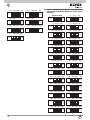
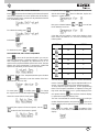
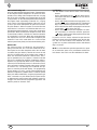
ADDITIONAL MODULE PUSHBUTTON HARDWARE
PROGRAMMING (ART. 8051, 8052, 8053, 8054, 12TS,
12TS/0, 639P)
The dip-switches modify the hardware code of the fi rst pu-
shbutton at the top right of the module, while the other pu-
shbuttons are associated consecutively from top to bottom,
right to left (see Tables 1 and 2). Take care not to overlap the
codes of pushbuttons on the same panel. When using the
modules with pushbuttons in single or double columns the
parameter “Single/Double pushbuttons” must be program-
med according to the type of module (see programming).
The confi guration of parameter “single push-buttons”
determines the numbering of push-buttons. If the “sin-
gle push-buttons” parameter is set to 2 or 3 take into
account the values in [ ] bracket, on the contrary if the
value is set to 0 or 1 take into account the values in {
} bracket.
TABLE 1 - PUSHBUTTONS IN A SINGLE COLUMN
Not to be used

8
GB
ON
12
16
8
ON
12
16
8
ON
12
16
8
ON
12
16
8
ON
123
128
64
32
ON
123
128
64
32
ON
123
128
64
32
ON
123
128
64
32
ON
12
16
8
ON
12
16
8
ON
12
16
8
ON
12
16
8
ON
123
128
64
32
ON
123
128
64
32
ON
123
128
64
32
ON
123
128
64
32
ON
12
16
8
ON
12
16
8
ON
12
16
8
ON
12
16
8
ON
123
128
64
32
ON
123
128
64
32
ON
123
128
64
32
ON
123
128
64
32
ON
12
16
8
ON
12
16
8
ON
12
16
8
ON
12
16
8
ON
123
128
64
32
ON
123
128
64
32
ON
123
128
64
32
ON
123
128
64
32
ON
12
16
8
ON
12
16
8
ON
12
16
8
ON
123
128
64
32
ON
123
128
64
32
ON
123
128
64
32
ON
12
16
8
ON
12
16
8
ON
12
16
8
ON
123
128
64
32
ON
123
128
64
32
ON
123
128
64
32
ON
12
16
8
ON
123
128
64
32
ON
12
16
8
ON
123
128
64
32
ON
12
16
8
ON
123
128
64
32
ON
12
16
8
ON
123
128
64
32
Non utilizzare 1 ... 8
9... 16
25 ... 32
41 ... 48
57 ... 64
73 ... 80
89 ... 96
105 ... 112
121 ... 128
137 ... 144
153 ... 160
169 ... 176
17 ... 24
33 ... 40
49 ... 56
65 ... 72
81 ... 88
97 ... 104
113 ... 120
129 ... 136
145 ... 152
161 ... 168
177 ... 184
185 ... 192 193 ... 200
{3 ... 10}]
[
{11 ... 18}
]
[
{19 ... 26}
]
[
{27 ... 34}]
[
{35 ... 42}]
[
{43 ... 50}]
[
{51 ... 58}]
[
{59 ... 66}]
[
{67 ... 74}]
[
{75 ... 82}]
[
{83 ... 90}]
[
{91... 98}]
[
{99 ... 106}
]
[
{107 ... 114}]
[
{115 ... 122}]
[
{123 ... 130}
]
[
{131 ... 138}
]
[
{139 ... 146}]
[
{147 ... 154}]
[
{155 ... 162}]
[
{163 ... 170}]
[
{171 ... 178}]
[
{179 ... 186}
]
[
{187 ... 194}]
[
{195 ... 200}]
[
TAB. 2 - PUSH-BUTTONS IN TWO ROWS OR TO BE
USED WITH ADDITIONAL MODULES TYPES 12TS/0
AND 693P
Not to be used
ON
123
16
8
4
ON
123
128
64
32
ON
123
16
8
4
ON
123
128
64
32
ON
123
16
8
4
ON
123
128
64
32
ON
123
16
8
4
ON
123
128
64
32
ON
123
16
8
4
ON
123
128
64
32
ON
123
16
8
4
ON
123
128
64
32
ON
123
16
8
4
ON
123
128
64
32
173 ... 176
181 ... 184
189 ... 192
197 ... 200
177 ... 180
185 ... 188
193 ... 196
{175 ... 178}
]
[
{179 ... 182}
]
[
{183 ... 186}
]
[
{187 ... 190}
]
[
{191 ... 194}
]
[
{195 ... 198}
]
[
{199 ... 200}
]
[

GB
9
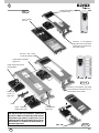
Art. RPF3
Additional module with
push-buttons
Art 6931
Audio speech unit
Art. 9192
Flush-mounted box
Art. RPF3
Microphone
Frame
Bracket with fi xing screws for
speech unit
Fig. 4B
If using the “BUSY - WAIT” si-
gnal, use the entrance panel
module 8000 series, Art.
80PA, otherwise Art. RPF3.
Art. 80PA
Fig. 4A

10
GB
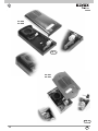
Fig. 5
Fig. 6
Art. 8911 + ART. R263
Art. 891D + ART. R263
Art. 88T1
Art. 88T2
ART. R263

GB
11
Art. 1220
Art. 1258
R693
Fig. 7
Fig. 7A
Art. 1222
Fig. 7B
ART. 264
Cover closing
the lens
Insertion of microphone
type 6931 (see instructions
instructions for entrance pa-
nels series 1200)
Bracket with fi xing screws
for speech unit
Bracket with fixing
screws for speech unit
Cable CN10 to module
type 12TS
Cable CN10 from speech
unit type 6931
Additional
module
type 12TS
From module
type 12TS
Other additional
module type 12TS
In a 1200 series entrance panel for a confi gura-
tion with more than 2 push-buttons, speech unit
type 6931 is fi tted in an audio/video plate without
push-buttons type 1220 by coupling one or more
additional plates with push-buttons type 125x for
the installation of additional modules with 4 pu-
sh-buttons type 12TS.
Insertion of microphone type 6931
(see instructions instructions for en-
trance panels series 1200)

12
GB
Fig. 8
Art. 2101
Art. 2102
Art. 8101
Art. 8102
Fig. 9

GB
13
Fig. 10
Art. 2550/301 + ART. R261
Art. 2550/302 + ART. R261
ART. R261
Art. 3301 + ART. R261
Art. 3302 + ART. R261
Fig. 11
ART. R261
Fig. 12

14
GB
12345
OK
R
R
ITALY
CN1
CN2
8
16
32
64
128
Art. 693P
ON
12345
OK
R
R
ITALY
CN1
CN2
8
16
32
64
128
Art. 693P
ON
12345
OK
R
R
ITALY
CN1
CN2
8
16
32
64
128
Art. 693P
ON
12345
OK
CONNETTORE
PER ART. 950C
CONNECTOR
FOR TYPE 950C
VOLUME INTERNO
INTERNAL UNIT VOLUME
TEMPO ATTIVAZIONE
ACTIVATION TIME
VOLUME ESTERNO
SPEECH UNIT VOLUME
PULSANTI
SUPPLEMENTARI
ADDITIONAL
PUSH-BUTTONS
A B C
TERMINAZIONE
BUS
BUS
TERMINATION
1
7
ART. / TYPE
6930
ID
4 3 2 1
1 - Microfono / Microphone
2 - CH2
3 - Occupato / Busy
4 - CH1
5 - Video
6 - Alim. LED / LED power
7 - Alim. interna LED / Internal power for LED
8 - Reset
2
3456
R
Made in Italy
DC 28V INT 6W
8
12345
OK
R
R
ITALY
CN1
CN2
8
16
32
64
128
Art. 693P
ON
CONNETTORE
PER ART. 950C
CONNECTOR
FOR TYPE 950C
VOLUME INTERNO
INTERNAL UNIT VOLUME
TEMPO ATTIVAZIONE
ACTIVATION TIME
VOLUME ESTERNO
SPEECH UNIT VOLUME
PULSANTI
SUPPLEMENTARI
ADDITIONAL
PUSH-BUTTONS
A B C
TERMINAZIONE
BUS
BUS
TERMINATION
1
7
ART. / TYPE
6930
ID
4 3 2 1
1 - Microfono / Microphone
2 - CH2
3 - Occupato / Busy
4 - CH1
5 - Video
6 - Alim. LED / LED power
7 - Alim. interna LED / Internal power for LED
8 - Reset
2
3456
R
Made in Italy
DC 28V INT 6W
8
2
2
1
Art. 693P/M
Art. 693P
Art. 6931
Art. 693P
Art. 6931
Art. 6931
Fig. 13
2
1
R
R
R
R
R
R
R
R
R
R
Long wires supplied with type 693P/M
Short wire supplied with type 693P
Wire supplied by the installer
Wires supplied
back box type 256S
Extensions
(Extensions)
back box type 256S

GB
15
ADVANCED SOFTWARE CONFIGURATIONS
The advanced confi gurations can be made via the programmer
Art. 950C or PC Software SaveProg (Art. 69CD) with interface
Art. 692I or Art. 692I/U by connecting it on the right-hand side
of the speech unit (see Fig. 14):
Fig. 14
The button has no function because the program-
mer is powered via the bus. For the same reason the au-
to-shutdown function is not available.
The programmer keys and enable selection
of the following item from the main menu:
During the phase of waiting for the response from the spe-
ech unit, the display shows:
After a few seconds the programmer display will show the
type and release of the software for the speech unit:
If the speech unit is connected to one of the modules
6570, 657C, 693T, the code 6931 is replaced by 693V.
When it disappears the fi rst item on the programming
menu will appear. The programming procedure ends ei-
ther due to timeout or by pressing the
button while
you are in any of the external menus listed below.
MESSAGE LANGUAGE
The programs can be run in Italian (local language, de-
fault) or in English. To change language, press
for
Italian or
for English.
To cancel press . To confi rm, press . Accep-
tance of the command, as in all cases, is shown on the
fi rst line of the display:
The display now changes to:
By pressing you move onto the previous item of the
programming menu.
The programmer keypad layout is as follows:
SOFTWARE CONFIGURA-
TIONS WITH PROGRAMMER

16
GB
To change mapping, press :
enter a number between 1 and 200.
To cancel press . To confi rm, press . Accep-
tance of the command, as in all cases, is shown on the fi rst
line of the display:
Afterwards you go back to see the new programming value
and you can continue with another pushbutton:
If the ID is outside the limit, the fi rst line of the display will
signal the incongruity:
Use keys and to move from one pushbutton to
another. From the position of pushbutton 1, press
. to
move to the next item in the programming menu. To cancel
all the remapping, instead of pressing a pushbutton or ente-
ring the number, press
:
You are asked to confi rm by pressing :
and then
Press or to cancel the
procedure. If remapping reset is selected, the following is
displayed:
And at the end:
FIRST BUTTON ID
Press button
to move to the next item by which you can
change the number of the audio/video door entry unit called in
correspondence with the pushbutton CH1 of the speech unit.
To change the ID, enter a number between 1 and 200.
To cancel press . To confi rm, press . Acceptance
of the command, as in all cases, is shown on the fi rst line of
the display
:
If the ID is outside the limit, the fi rst line of the display will
signal the incongruity:
By pressing you move onto the previous item of the
programming menu.
REMAPPING PUSHBUTTONS (HARDWARE / SOFTWARE
CONVERSION)
Press
to move to the next item by which you can change
the number of the mointor called in correspondence with any
pushbutton of the speech unit. When programmed accordin-
gly, the user can set the system so that several pushbuttons
call the same intephone/ monitor. By default each pushbutton
calls the intephone/ monitor door entry unit corresponding to
the physical position on the keypad. This is indicated by the
value 0 on the conversion table:
To change the pushbutton to resign, press it directly or key in
the digits so as to form a number between 1 and 200.
In the second case, to cancel press . To confi rm the
pushbutton, press
.

GB
17
Press to pass quickly, skipping all the intermediate
steps, onto the previous item of the programming menu.
SINGLE PUSHBUTTONS
Press
to move to the next item by which you can cho-
ose from the pushbuttons on one (default) or two columns.
To change the confi guration, press
for a single column:
or
for a double column. To cancel press . Pro-
gramming is confi rmed with
:
As push-button number extension you can choose the use of
only external push-buttons, either in single either in double
row. To do this instead of
you can use .
instead of
you can use .
Press
to move to the previous item of the programming
menu.
LOCK TIME
Press
to move to the next item by which you can change
the time for which the lock is activated whether controlled by
intephone/ monitor or locally via the AC terminal of the termi-
nal block.
When controlled by an intephone/ monitor, the Lock Block
described below is observed.
What is shown corresponds to the current value:
By keying in the digits, the time can be changed in steps of
one second:
To cancel press . To confi rm, press . Acceptance
of the command, as in all cases, is shown on the fi rst line of
the display
If the time is outside the limit, that is longer than 5 seconds,
the fi rst line of the display will signal the incongruity:
By pressing you move onto the previous item of the
programming menu.
LOCK BLOCK
Press
to move to the next item by which you can acti-
vate or deactivate (default) the lock command block by an
intephone/ monitor. When the block is inserted, the door lock
can be activated only if the interphone/video interphone is
called by the speech unit, or in conversation with it or it has
self inserted.
The current value is shown on display:
Press
to activate the block, press to eliminate it:
To cancel press
. To confi rm, press . Acceptance
of the command, as in all cases, is shown on the fi rst line of
the display
Press to move onto the previous item of the program-
ming menu.

18
GB
ENABLING / DISABLING
Press
to move to the next item by which, for each de-
vice, you can program controls on some commands that the
speech unit receives.
It is possible to confi gure one or more speech units so they do
not react, for one or more intephone/ monitor, on activating
the lock that would derive from the programming described in
the single paragraphs.
On the contrary, it is possible to program the speech unit so
as to permit activation only by some intephone/ monitor. To
run the minimum number of programs, if the speech unit has
at least one programmed common lock, the items function
as enabling signals. If no settings are entered, the items fun-
ction as disable selections. Given that the common locks are
usually used in locations such as building complexes, less
settings may be made by programming one common lock and
enabling only the users of the relative stairway.
For example a main speech unit (the outermost one) calls 4
monitors in one building and 1 in an annex. The building has
in its turn a speech unit at the bottom of the stairway that calls
the only 4 monitors in the building. The speech unit at the
bottom of the stairway must be programmed with the lock in
common with the main one so that when the lock of the main
speech unit is operated the one at the bottom of the stairway
is governed as well to create a prearranged route. The annex
is also called from the main speech unit, but if the lock is acti-
vated, the stairway lock does not react because access to the
annex is via a separate path. To obtain this condition, only the
IDs of the video door entry units in the same stairway should
be selected on the speech unit at the bottom of the stairway so
as to avoid activation of the lock by the monitor in the annex.
There is no disable selection by default. The lack of disable
selection is indicated by “—“. To change the ID of the audio /
video door entry unit press buttons and .
Otherwise, enter the number of the audio / video door entry
unit, from 1 to 200:
To cancel, press . To confi rm, press .
To modify disable selections of the selected audio / video door
entry unit, starting from where the current value is shown,
press
.
The correspondence between disable selections, symbols
and keys is as follows:
Press one key alternately to add / remove the corresponding
function. To cancel, press
. To confi rm, press .
Acceptance of the command, as in all cases, is shown on the
fi rst line of the display:
Press
to move quickly, skipping all the intermediate
steps, to the previous item of the programming menu.
To change the settings of all the audio/video door entry units,
the procedure is as follows. For the ID key in no. 0. The
display shows :
Use buttons , , , to select what to do,
that is whether to engage or release the lock for all. The fol-
lowing table shows the actions.
PUSH-BUTTON ACTION
Do not do anything
Deselect De (for compatibillty)
Deselect De
Select De
To confi rm, press
. To cancel press .
SOUND IN THE SPEECH UNIT
Press
to move to the next item by which you can acti-
vate (default) or deactivate the call control tone in the speech
unit. The current value is shown on display:
Press
to activate the sound, press to eliminate
it:
OBSTACLE ABBREVIATION PUSH-BUTTON
Door lock De 1

GB
19
To cancel press . To confi rm, press . Acceptance
of the command, as in all cases, is shown on the fi rst line of the
display:
Press to move onto the previous item of the program-
ming menu.
RINGTONE CYCLE NUMBER
Press
to move to the next item by which you can change
the number of call cycles emitted by the speech unit. Each
ringtone cycle follows the rhythm of 1 s ringtone and 2 s pause,
which means each cycle lasts 3 s. What is shown corresponds
to the current value:
By keying in the digits, the number of cycles can be changed:
To cancel press . To confi rm, press . Acceptance
of the command, as in all cases, is shown on the fi rst line of the
display:
Press to move onto the previous item of the program-
ming menu.
CONTROLLER PUSHBUTTON
Press
to move to the next item by which you can pro-
gram which pushbuttons may be associated with the call of one
of the four porter’s lodge controllers contemplated in the
ELVOX 2-WIRE system.
By default there is no assignment:
Enter a number between 1 and 200:
To cancel, press . To confi rm, press . Acceptance
of the command, as in all cases, is shown on the fi rst line of the
display:
If the ID is outside the limit, the fi rst line of the display will
signal the incongruity:
To cancel the assignment, enter 0 for the ID.
It is possible to move from one pushbutton to another also by
using
and . From the position of pushbutton 1,
press
to move to the next item of the programming
menu.
Press
to move quickly, skipping all the intermediate
steps, to the previous item of the programming menu.
COMMON LOCKS
Press
to move to the next item by which you can pro-
gram for which other lock operations the current speech unit
must activate its output. In practice the lock output of a spe-
ech unit can be activated not only by a direct command, but
indirectly because the lock of another speech unit (at most
another four) has been commanded. It is clear that in this
case any Lock Block is not respected. By default there is no
assignment:
Enter a number between 1 and 15, i.e. the ID of an entrance
panel (in this case the fi rst of four possible choices) for con-
trolling whose lock also the current speech unit must activate
its own:
To cancel, press . To confi rm, press . Accep-
tance of the command, as in all cases, is shown on the fi rst
line of the display:
If the ID is outside the limit, the fi rst line of the display will
signal the incongruity:
To cancel the assignment, enter 0 for the ID.
It is possible to move from one index to another also by using
and .From position 1, press to move to
the next item of the programming menu. Press
to move
quickly, skipping all the intermediate steps, to the previous
item of the programming menu.

20
GB
SELF-INSERTION / SELF-START DISABLING
Press
to move to the next item by which the main speech
unit can be confi gured so as not to perform the self-insertion /
self-start function at the system level. By default the function
is on, do disabling is NO:
To activate the setting, press :
Followed by :
To deactivate it, press and .
SELF-INSERTION / SELF-START SEQUENCE
Press
to move to the next item by which you can pro-
gram the self-insertion / self-start sequence of the speech
units, interphone by interphone. By default there is no se-
quence and so only the MASTER speech unit is used. The item
appears only if the programmer is connected to a MASTER
speech unit, otherwise you move to the next function.
To change the ID of the interphone/monitor press buttons
and . Otherwise, enter the number of the inter-
phone/monitor, from 1 to 200:
To cancel, press . To confi rm, press . To change
the sequence of the selected interphone/monitor, starting from
where the current value is shown, press
.
To specify the sequence of entrance panels, use the ..
buttons for the fi rst 9 entrance panels.
For panels with ID greater than 9, a prefi x mechanism is used
with the aid of button
. Press it a fi rst time, in place of a
digit the ‘?’ symbol appears
Now, press a button between and so as to form
the ID between 10 and 15
.
Given that only one location is used on the display to show
these values, the letters A to F are used, according to the
following table:
The last ID present in the sequence can be cancelled by
means of the key
. IDs may be duplicated within a se-
quence. The maximum limit is 15 per interphone/monitor.
To help compose equal sequences, for this programming
there is the concept of “notebook” or “clipboard”. During edi-
ting mode, and when there is no ‘?’ symbol displayed, if the
user presses the key
, the sequence shown on display
is copied into a temporary memory zone.
The user can terminate the current sequence, by moving to
another interphone/monitor and pressing
, thus recal-
ling this memory which replaces the one present. To cancel
press
To confi rm, press . Acceptance of the
command, as in all cases, is shown on the fi rst line of the
display:
BUTTON ID LETTER LETTER
10 A
11 B
12 C
13 D
14 E
15 F
La pagina si sta caricando...
La pagina si sta caricando...
La pagina si sta caricando...
La pagina si sta caricando...
La pagina si sta caricando...
La pagina si sta caricando...
La pagina si sta caricando...
La pagina si sta caricando...
La pagina si sta caricando...
La pagina si sta caricando...
La pagina si sta caricando...
La pagina si sta caricando...
La pagina si sta caricando...
La pagina si sta caricando...
La pagina si sta caricando...
La pagina si sta caricando...
La pagina si sta caricando...
La pagina si sta caricando...
La pagina si sta caricando...
La pagina si sta caricando...
La pagina si sta caricando...
La pagina si sta caricando...
La pagina si sta caricando...
La pagina si sta caricando...
La pagina si sta caricando...
La pagina si sta caricando...
La pagina si sta caricando...
La pagina si sta caricando...
La pagina si sta caricando...
La pagina si sta caricando...
La pagina si sta caricando...
La pagina si sta caricando...
La pagina si sta caricando...
La pagina si sta caricando...
La pagina si sta caricando...
La pagina si sta caricando...
La pagina si sta caricando...
La pagina si sta caricando...
La pagina si sta caricando...
La pagina si sta caricando...
La pagina si sta caricando...
La pagina si sta caricando...
La pagina si sta caricando...
La pagina si sta caricando...
-
 1
1
-
 2
2
-
 3
3
-
 4
4
-
 5
5
-
 6
6
-
 7
7
-
 8
8
-
 9
9
-
 10
10
-
 11
11
-
 12
12
-
 13
13
-
 14
14
-
 15
15
-
 16
16
-
 17
17
-
 18
18
-
 19
19
-
 20
20
-
 21
21
-
 22
22
-
 23
23
-
 24
24
-
 25
25
-
 26
26
-
 27
27
-
 28
28
-
 29
29
-
 30
30
-
 31
31
-
 32
32
-
 33
33
-
 34
34
-
 35
35
-
 36
36
-
 37
37
-
 38
38
-
 39
39
-
 40
40
-
 41
41
-
 42
42
-
 43
43
-
 44
44
-
 45
45
-
 46
46
-
 47
47
-
 48
48
-
 49
49
-
 50
50
-
 51
51
-
 52
52
-
 53
53
-
 54
54
-
 55
55
-
 56
56
-
 57
57
-
 58
58
-
 59
59
-
 60
60
-
 61
61
-
 62
62
-
 63
63
-
 64
64


Elvox 6931 Istruzioni per l'uso
- Categoria
- Impianti citofonici
- Tipo
- Istruzioni per l'uso
in altre lingue
- English: Elvox 6931 Operating instructions
Documenti correlati
-
Elvox 693T Istruzioni per l'uso
-
-
-
-
-
-
-
Elvox 1286 Installer's Manual
-
-
Altri documenti
-
Aiphone GF-2B Manuale utente
-
Aiphone GT Istruzioni per l'uso
-
Bticino 342630 Manuale utente
-
-
-
-
Levenhuk CN10 Bug Collector Jar Manuale utente
-
 Thomashilfen Grip rail, grey Assembly Instructions
-
Philips 346184816 Guida Rapida
