La pagina si sta caricando...

Publication 22C-PC001D-EN-P - January 2017
Product Information
PowerFlex 400 Adjustable Frequency AC
Drive
Catalog Number 22C, Series B
Additional Resources
These documents contain additional information concerning the installation, programming, and application
of the AC drive.
Mounting Considerations
• Mount the drive upright on a flat, vertical and level surface.
• Protect the cooling fan by avoiding dust or metallic particles.
• Do not expose to a corrosive atmosphere.
• Protect from moisture and direct sunlight.
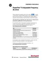
Minimum Mounting Clearances
Frame C Mounting Clearances
Frames D, E and F Mounting Clearances
Frames G and H Mounting Clearances
Ambient Operating Temperatures
Drive Dimensions
PowerFlex 400 Frames
PowerFlex 400 Frames C...H
Dimensions are in mm and (in.). Weights are in kg and (lb).
Specifications, Fuses and Circuit Breakers
ATTENTION:
• Before installing, configuring, operating or maintaining this product,
read this document and the documents listed in the Additional
Resources section for installing, configuring, or operating
equipment. Usersshould familiarize themselves with installation and
wiring instructions in addition to requirements of all applicable
codes, laws, and standards.
•Installation, adjustments, putting into service, use, assembly, disassembly,
and maintenance shall be carried out by suitably trained personnel in
accordance with applicable code of practice.
•If this equipment is used in a manner not specified by the manufacturer, the
protection provided by the equipment may be impaired.
•Solid state equipment has operational characteristics differing from those of
electromechanical equipment. Safety Guidelines for the Application,
Installation and Maintenance of Solid State Controls, publication SGI-1.1,
available from your local Rockwell Automation sales office or online at
http://www.rockwellautomation.com/literature describes some important
differences between solid state equipment and hard-wired
electromechanical devices.
ATTENTION: Do not install, configure, operate or maintain this product until you have read
the product documentation and the documents in the Additional Resources section for
installing, configuring, operating or maintaining equipment. To get the product
documentation go to
http://www.rockwellautomation.com/literature or contact your local
sales office or Rockwell Automation representative.
ATTENTION: Ne pas installer, configurer, exploiter ou maintenir ce produit tant que vous
n’avez pas lu sa documentation et les documents de la rubrique Documents connexes pour
l’installation, la configuration, l’exploitation et la maintenance de l’équipement. Pour obtenir
de la documentation, rendez-vous sur le site
http://www.rockwellautomation.com/literature
ou contactez votre agence commerciale Rockwell Automation locale ou son représentant.
ACHTUNG: Für die Installation, Konfiguration, den Betrieb und die Wartung dieses Produkt
lesen Sie sich bitte zunächst die Produktdokumentation sowie die Dokumente im Abschnitt
"Weitere Informationen" durch. Die entsprechende Produktdokumentation finden Sie unter
http://www.rockwellautomation.com/literature oder kontaktieren Sie Ihr lokales
Vertriebsbüro bzw. einen Rockwell Automation-Mitarbeiter.
ATENCIÓN: No instale, configure, opere ni mantenga este producto hasta que haya leído la
documentación del producto y los documentos en la sección Recursos adicionales para la
instalación, configuración, operación o mantenimiento de equipo. Para conseguir la
documentación, diríjase a
http://www.rockwellautomation.com/literature o póngase en
contacto con su oficina regional de ventas o representante de Rockwell Automation.
ATENÇÃO: Não instale, configure, opere ou mantenha este produto até que você leia a
documentação do produto e os documentos na seção Recursos adicionais para a instalação,
configuração, operação ou manutenção do equipamento. Para conseguir a documentação,
visite
http://www.rockwellautomation.com/literature ou entre em contato con seu escritório
de vendas regional ou representante da Rockwell Automation.
ATTENZIONE: Non installare, configurare, attivare o riparare questo prodotto senza avere
prima letto la relativa documentazione nonchè i documenti indicati nella sezione Ulteriori
Risore riguardanti l'installazione, la configurazione, l'attivazione o la riparazione
dell'apparecchiatura. Per la documentazione sul prodotto visitare il sito
http://www.rockwellautomation.com/literature o contattare l'ufficio vendite o il
rappresentate Rockwell Automation di zona.
ВНИМАНИЕ: Не устанавливайте, не конфигурируйте, не запускайте в эксплуатацию и не
поддерживайте работу продукта до прочтения технической документации по продукту
и документации в разделе Дополнительные материалы для инсталлирования,
конфигурирования, запуска в эксплуатацию и поддержки работы продукта. Чтобы
ознакомиться с документацией по продукту, перейдите по ссылке
http://www.rockwellautomation.com/literature или свяжитесь с локальным офисом
продаж или представителем Rockwell Automation.
UWAGA: Nie instaluj i nie uruchamiaj tego urządzenia dopóki nie zapoznasz się z instrukcją
użytkownika produktu. Aby uzyskać dokumentację produktu przejdź do strony internetowej
http://www.rockwellautomation.com/literature lub skontaktuj się z lokalnym biurem
sprzedaży lub przedstawicielstwem firmy Rockwell Automation.
UPOZORŇENÍ: Neprovádějte instalaci, konfiguraci, provoz ani údržbu, pokud jste dosud
nepřečetli dokumentaci k produktu a dokumenty obsažené v sekci Doplňující informace pro
instalaci, konfiguraci, provoz a údržbu. Tuto dokumentaci můžete získat na
http://www.rockwellautomation.com/literature nebo od obchodního zástupce společnosti
Rockwell Automation.
English This instruction sheet is available in multiple languages at
http://www.rockwellautomation.com/literature. Select publication language and type
“22C-QS001“ in the search field.
Deutsch Diese Anleitung steht in mehreren Sprachen unter
http://www.rockwellautomation.com/literature zur Verfügung. Wählen Sie Ihre Sprache aus,
und geben Sie „22C-QS001“ in das Suchfeld ein.
Français Ces instructions sont disponibles dans différentes langues à l’adresse suivante:
http://www.rockwellautomation.com/literature. Sélectionner la langue puis taper
« 22C-QS001 » dans le champ de recherche.
Italiano La presente scheda d’istruzione è disponibile in varie lingue sul sito
http://www.rockwellautomation.com/literature. Selezionare la lingua desiderata e digitare
“22C-QS001“ nel campo di ricerca.
Español Puede encontrar esta hoja de instrucciones en varios idiomas en
http://www.rockwellautomation.com/literature. Selecione el idioma de publicación y
escriba “22C-QS001“ en el campo de búsqueda.
Português Esta folha de instruções está disponível em várias línguas em
http://www.rockwellautomation.com/literature. Seleccione a língua de publicação e entre
com “22C-QS001“ no espaço de busca.
ᵈᗧ㧦
ᵈᗧ㧦
ຠߩ⾗ᢱ߅ࠃ߮ㅊട⾗ᢱߦ⸥タߩⵝ⟎ߩขઃߌޔ᭴ᚑޔᠲޔ
߹ߚߪߦ㑐ߔࠆ⾗ᢱࠍ߅⺒ߺߦߥࠆ߹ߢߪޔߎߩຠߩขઃߌޔ
᭴ᚑޔᠲޔ߹ߚߪࠍⴕߥࠊߥߢߊߛߐޕຠߩ⾗ᢱࠍ
ᚻߔࠆߦߪ ޔ9GDࠨࠗ࠻㧦http://www.rockwellautomation.com/literature ߦ
ࠕࠢࠬߔࠆ߆ޔ߹ߚߪࡠ࠶ࠢ࠙ࠚ࡞ࠝ࠻ࡔ࡚ࠪࡦߩ༡ᬺ߹ߚߪ
⽼ᄁઍℂᐫ߹ߢߏㅪ⛊ߊߛߐޕ
:
:
, , ,
.
http://www.rockwellautomation.com/literature
.
“ ”
http://www.rockwellautomation.com/literature
http://www.rockwellautomation.com/literature
http://www.rockwellautomation.com/literature
.
"22C-QS001" .
( )
:
http://www.rockwellautomation.com/literature
,
ᣣᧄ
ᧄ⺑ᦠࠪ࠻ߩᄙ⸒⺆ ߪ9GDࠨࠗ࠻http://www.rockwellautomation.com/literature
ߦߡᚻߢ߈ߔޕ ⸒⺆ࠍㆬᛯߒޔᬌ⚝ࡈࠖ࡞࠼ߦޟ%35ޠ
ߣ࠲ࠗࡊߒߡߊߛߐޕ
Русский Данное руководство на других языках можно найти по адресу
http://www.rockwellautomation.com/literature. Выберите язык и введите в окно поиска
«22C-QS001».
Český Tato stránka s pokyny je k dispozici ve více jazykových verzích na adrese
http://www.rockwellautomation.com/literature. Zvolte jazyk publikace a do vstupního pole
pro vyhledávání zadejte „22C-QS001“.
Polski Niniejsza instrukcja dostępna jest w wielu językach na stronie
http://www.rockwellautomation.com/literature. Wybrać język publikacji, w polu
wyszukiwania wpisać “22C-QS001”.
PowerFlex 400 User Manual
22C-UM001: Detailed information on the parameters and specifications of the
PowerFlex 400 adjustable frequency drive.
AC Drive Installation Considerations
DRIVES-IN003: Provides additional information needed to properly
install PowerFlex AC drives.
Wiring and Grounding Guidelines for Pulse Width Modulated (PWM) AC Drives, publication
DRIVES-IN001:
Provides basic information needed to properly wire and ground PWM AC drives.
Industrial Automation Wiring and Grounding Guidelines
1770-4.1: Provides general guidelines for
installing a Rockwell Automation industrial system.
Frame Screw Size Screw Torque
C M5 (#10...24) 2.45...2.94 Nm (22...26 lb-in.)
D M8 (5/16 in.) 6.0...7.4 Nm (53.2...65.0 lb-in.)
E M8 (5/16 in.) 8.8...10.8 Nm (78.0...95.3 lb-in.)
F M10 (3/8 in.) 19.6...23.5 Nm (173.6...208.3 lb-in.)
G M12 (1/2 in.) 33.5...41.0 Nm (296.5...362.9 lb-in.)
H M12 (1/2 in.) 33.5...41.0 Nm (296.5...362.9 lb-in.)
Frame Temperature Range Enclosure Rating Minimum Mounting
Clearances
C -10...45 °C (14...113 °F) IP20/UL Open Type Use Mounting Option A
-10...45 °C (14...113 °F) IP30/NEMA 1/UL Type 1
(1)
(1)
Frame C drives require installation of the PowerFlex 400 IP30/NEMA 1/UL Type 1 option kit to achieve this
rating.
Use Mounting Option B
-10...50 °C (14...122 °F) IP20/UL Open Type Use Mounting Option B
D, E, F,
G, H
-10...45 °C (14...113 °F) IP30/NEMA 1/UL Type 1 See Frames D, E and F Mounting Clearances
and Frames G and H Mounting Clearances
http://www.rockwellautomation.com/literature
Ā&46ā
120 mm
(4.7 in.)
120 mm
(4.7 in.)
25 mm
(1.0 in.)
120 mm
(4.7 in.)
120 mm
(4.7 in.)
120 mm
(4.7 in.)
120 mm
(4.7 in.)
120 mm
(4.7 in.)
120 mm
(4.7 in.)
Mounting Option A
No clearance required
between drives.
Mounting Option B
Closest object that
may restrict air flow
through the drive heat
sink and chassis
150 mm
(6.0 in.)
150 mm
(6.0 in.)
50 mm
(2.0 in.)
50 mm
(2.0 in.)
250 mm
(9.8 in.)
150 mm
(6.0 in.)
50 mm
(2.0 in.)
50 mm
(2.0 in.)
Frame D and E Frame F
300 mm
(11.8 in.)
300 mm
(11.8 in.)
300 mm
(11.8 in.)
300 mm
(11.8 in.)
Output Power Frame Size
kW HP 200...240V AC Input 400...480V AC Input
2.2...7.5 3...10 C C
11...15 15...20 D C
18.5...22 25...30 D D
30...37 40...50 E E
45...75 60...100 – E
90...110 125...150 – F
132...160 200...250 – G
200...250 300...350 – H
Drive Ratings
Catalog No. Output Rating Input Rating Branch Circuit Protection Power
Dissi-
pation
kW
(HP)
Amps Voltage
Range
kVA Amps Fuses
(1)
(1)
Recommended Fuse Type: UL Class J, CC, T or Type BS88; 600V (550V) or equivalent.
140M Motor
Protectors
(2) (3) (4)
(2)
Refer to the MCS Miniature Modular Control System Selection Guide, publication MCS-SG001 to determine
the frame and breaking capacity required for your application.
(3)
The AIC ratings of the Bulletin 140M Motor Protector Circuit Breakers may vary. See Bulletin 140M Motor
Protection Circuit Breakers Application Ratings.
(4)
Manual Self-Protected (Type E) Combination Motor Controller, UL listed for 208 Wye or Delta, 240 Wye or
Delta, 480Y/277 or 600Y/347. Not UL listed for use on 480V or 600V Delta/Delta, corner ground, or
high-resistance ground systems.
Min.
Enclosure
Volume
(5)
(in.
3
)
(5)
When using a Manual Self-Protected (Type E) Combination Motor Controller, the drive must be installed in a
ventilated or non-ventilated enclosure with the minimum volume specified in this column. Application specific
thermal considerations may require a larger enclosure.
IP20
Open
Watts
50 °C
200...240V AC – 3-Phase Input, 0...230V 3-Phase Output
22C-B012N103 2.2 (3.0) 12 180...265 6.5 15.5 20 140M-F8E-C16 5098 146
22C-B017N103 3.7 (5.0) 17.5 180...265 8.8 21 30 140M-F8E-C25 5098 207
22C-B024N103 5.5 (7.5) 24 180...265 10.9 26.1 35 140M-F8E-C32 5098 266
22C-B033N103 7.5 (10) 33 180...265 14.4 34.6 45 140M-F8E-C45 5098 359
22C-B049A103 11 (15) 49 180...265 21.3 51 70 – – 488
22C-B065A103 15 (20) 65 180...265 28.3 68 90 – – 650
22C-B075A103 18.5 (25) 75 180...265 32.5 78 100 – – 734
22C-B090A103 22 (30) 81 180...265 38.3 92 125 – – 778
22C-B120A103 30 (40) 120 180...265 51.6 124 175 – – 1055
22C-B145A103 37 (50) 130 180...265 62.4 150 200 – – 1200
380...480V AC – 3-Phase Input, 0...460V 3-Phase Output
22C-D6P0N103 2.2 (3.0) 6 340...528 6.3 7.5 10 140M-D8E-C10 5098 105
22C-D010N103 4.0 (5.0) 10.5 340...528 10.9 13 20 140M-D8E-C16 5098 171
22C-D012N103 5.5 (7.5) 12 340...528 11.9 14.2 20 140M-D8E-C16 5098 200
22C-D017N103 7.5 (10) 17 340...528 15.3 18.4 25 140M-D8E-C20 5098 267
22C-D022N103 11 (15) 22 340...528 19.2 23 30 140M-F8E-C32 5098 329
22C-D030N103 15 (20) 27 340...528 25.8 31 40 140M-F8E-C32 5098 435
22C-D038A103 18.5 (25) 38 340...528 33.3 40 50 140M-F8E-C45 9086 606
22C-D045A103 22 (30) 45.5 340...528 39.1 47 60 – – 738
22C-D060A103 30 (40) 54 340...528 53.3 64 80 – – 664
22C-D072A103 37 (50) 72 340...528 60.7 73 100 – – 1019
22C-D088A103 45 (60) 88 340...528 74.9 90 125 – – 1245
22C-D105A103 55 (75) 105 340...528 89 107 150 – – 1487
22C-D142A103 75 (100) 128 340...528 124.8 150 200 – – 2043
22C-D170A103 90 (125) 170 340...528 142 170 250 – – 2617
22C-D208A103 110 (150) 208 340...528 167 200 250 – – 3601
22C-D260A103 132 (200) 260 340...528 196 235 300 – – 3711
22C-D310A103 160 (250) 290 340...528 242 290 400 – – 4208
22C-D370A103 200 (300) 370 340...528 304 365 500 – – 4916
22C-D460A103 250 (350) 410 340...528 387 465 600 – – 6167
Agency Certifications
Listed to UL508C and CAN/CSA-22.2 Certified to AS/NZS, 1997 Group 1,
Class A
Marked for all applicable European Directives
EMC Directive: 2014/30/EU: EN 61800-3
LV Directive: 2014/35/EU: EN 61800-5-1
The drive is also designed to meet the appropriate portions of the following specifications:
NFPA 70 – US National Electrical Code
NEMA ICS 3.1 – Safety standards for Construction and Guide for Selection, Installation and Operation
of Adjustable Speed Drive Systems.
IEC 146 – International Electrical Code.
Control Inputs
Digital inputs, programmable/semi-programmable Analog inputs, isolated -10...10V or 4...20 mA/
non-isolated 0...10V or 4...20 mA
SRC (Source) mode:
18...24V = ON
0...6V = OFF
SNK (Sink) mode:
0...6V = ON
18...24V = OFF
Resolution: 10-bit
4...20 mA analog: 250 input impedance
0...10V DC analog: 100 k input impedance
External pot: 1...10 k, 2 W min
Control Outputs
Relay output, programmable
form C
Resistive rating: 3.0 A @ 30V DC,
125V AC and 240V AC
Inductive rating: 0.5 A @ 30V DC,
125V AC and 240V AC
Opto outputs, programmable
30V DC, 50 mA non-inductive
Analog output, non-isolated
Resolution: 10-bit
0...10V DC analog: 1 k min
4...20 mA analog: 525 max
Protective Features
Motor Protection:
I
2
t overload protection – 110% for 60 s (Provides Class 10 protection)
Overcurrent: 180% hardware limit, 220% instantaneous fault
A
E
B
D
105.8
(4.17)
24.5
(0.96)
138.2
(5.44)
C
244
(9.61)
300
(11.81)
325
(12.8)
Frame
AB CDE
Weight
(1)
(1)
Weights include HIM and Standard I/O.
C 130.0 (5.1) 260.0 (10.2) 180.0 (7.1) 116.0 (4.57) 246.0 (9.7) 4.33 (9.5)
D 250.0 (9.84) 436.2 (17.17) 206.1 (8.11) 226.0 (8.90) 383.4 (15.09) 14.0 (30.9)
E 370.0 (14.57) 605.5 (23.84) 259.2 (10.21) 335.0 (13.19) 567.4 (22.34) 51.2 (112.9)
F 425.0 (16.73) 850.0 (33.46) 264.0 (10.39) 381.0 (15.00) 647.5 (25.49) 88.0 (194.0)
G 425.0 (16.73) 892.0 (35.12) 264.0 (10.39) 381.0 (15.00) 819.5 (32.26) 106 (233.7)
H 529.2 (20.83) 1363.8 (53.69) 358.6 (14.12) 480.0 (18.90) 1119.0 (44.06) 177 (390.2)
IP20/66 (NEMA Type 1/4X/12)
Flange Mount for Frame CIP20/NEMA/UL Type Open
U
L
®
CUS

Publication 22C-PC001D-EN-P – January 2017
Supersedes Publication 22C-PC001C-EN-P – October 2014 Copyright © 2017 Rockwell Automation, Inc. All rights reserved.
Allen-Bradley, Rockwell Software, Rockwell Automation , PowerFlex, and TechConnect are trademarks of Rockwell Automation, Inc.
Trademarks not belonging to Rockwell Automation are property of their respective companies.
Control Terminal Block
Power Wiring
Power Terminal Blocks
Power Terminal Block Specifications
General Grounding Requirements
Prepare For Drive Start-Up
Integral Keypad
Operator Keys
LED Status Indicators
Smart Start-Up with Basic Program Group Parameters
The PowerFlex 400 is designed so that start up is simple and efficient. The Program Group contains the most
commonly used parameters.
Fault Codes
To clear a fault, press the Stop key, cycle power or set A100 [Fault Clear] to 1 or 2.
Rockwell Automation Support
Rockwell Automation provides technical information on the Web to assist you in using its products.
At
http://www.rockwellautomation.com/support/, you can find technical manuals, a knowledge base of
FAQs, technical and application notes, sample code and links to software service packs, and a MySupport
feature that you can customize to make the best use of these tools.
For an additional level of technical phone support for installation, configuration, and troubleshooting, we
offer TechConnect support programs. For more information, contact your local distributor or Rockwell
Automation representative, or visit
http://www.rockwellautomation.com/support/.
Installation Assistance
If you experience a problem within the first 24 hours of installation, review the information that is contained
in this manual.
You can contact Customer Support for initial help in getting your product up and running.
New Product Satisfaction Return
Rockwell Automation tests all of its products to ensure that they are fully operational when shipped from the
manufacturing facility.
However, if your product is not functioning and needs to be returned, follow these procedures.
Documentation Feedback
Your comments will help us serve your documentation needs better. If you have any suggestions on how to
improve this document, complete this form, publication
RA-DU002, available at
http://www.rockwellautomation.com/literature/.
Over Voltage:
200...240V AC Input – Trip occurs @ 405V DC bus voltage (equivalent to 290V AC incoming line)
380...460V AC Input – Trip occurs @ 810V DC bus voltage (equivalent to 575V AC incoming line)
Under Voltage:
200...240V AC Input – Trip occurs @ 210V DC bus voltage (equivalent to 150V AC incoming line)
380...480V AC Input – Trip occurs @ 390V DC bus voltage (equivalent to 275V AC incoming line)
Trip:
Ground fault: Phase-to-ground on drive output
Short circuit: Phase-to-phase on drive output
Control Ride Through: Minimum ride through is 0.5 s - typical value 2 s
Faultless Power Ride Through: 100 ms
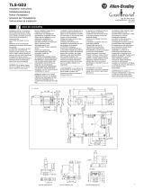
Terminal
(1)
Description
R/L1, S/L2, T/L3 3-Phase Input
U/T1 To Motor U/T1
Switch any two motor leads to
change forward direction.
V/T2 To Motor V/T2 =
W/T3 To Motor W/T3
P2, P1 DC Bus Inductor Connection
Drives are shipped with a jumper between Terminals P2 and P1.
Remove this jumper only when a DC Bus Inductor will be connected.
Drive will not power up without a jumper or inductor connected.
DC+, DC- DC Bus Connection (Frame C Drives)
P2, DC- DC Bus Connection (Frame D, E and F Drives)
BR+, BR- Not Used
Safety Ground – PE
04
05
06
07
01
02
03
08
09
10
12
13
14
15
16
17
18
19
20
11
Digital Common
Digital Common
Digital Input 1
Digital Input 2
Digital Input 3
Stop/
Function Loss
(1)(4)
Start/Run FWD
(2)
Direction/Run REV
Digital Input 4
Opto Common
R1
R2
R3
#1 Relay N.O.
#1 Relay Common
#1 Relay N.C.
+24V DC Source
+10V DC Source
Analog Input 1 (AI1)
Analog Common 1
Analog Output 2 (AO2)
Analog Output 1 (AO1)
Analog Input 2 (AI2)
Analog Common 2
(6)
Opto Output
RS485 Shield
+24V
+10V
R4
R5
R6
#2 Relay N.O.
#2 Relay Common
#2 Relay N.C.
Typical
SNK Wiring
Typical
SRC Wiring
RS485
(DSI)
Enable
(4)
Jumper
30V DC
50 mA
Non-inductive
Common
24V
ENBL
(3)
Pot must be
1...10k ohm
2 W min.
SRCSNK
SNK
SRC
Earth Referenced
Frames D & E
(5)
0...10V
0...20 mA
0...10V
0...20 mA
0...10V
0...20 mA
1 of 7 Digital Input Circuits
10V
20 mA
AO1
10V
20 mA
AO2
10V
20 mA
AI1
10V
20 mA
AI2
Isolated
Control Wiring Block Diagram
P036 [Start Source] Stop I/O Terminal 01 Stop
Keypad Per P037 Coast
3-Wire Per P037 Per P037
(4)
2-Wire Per P037 Coast
RS485 Port Per P037 Coast
(1) Important: I/O Terminal 01 is always a coast to stop input except when P036 [Start Source] is set to
option 1 “3-Wire”or 6 “2-W Lvl/Enbl”. In three wire control, I/O Terminal 01 is controlled by
P037 [Stop Mode]. All other stop sources are controlled by P037 [Stop Mode].
Important: The drive is shipped with a jumper installed between I/O Terminals 01 and 11. Remove this
jumper when using I/O Terminal 01 as a stop or enable input.
(2) Two wire control show. For three wire control use a momentary input on I/O Terminal 02 to
command a start. If reverse is enabled by A166, use a maintained input for I/O Terminal 03 to
change direction.
(3) When using an opto output with an inductive load such as a relay, install a recovery diode parallel to the
relay as shown, to prevent damage to the output.
(4) When the ENBL jumper is removed, I/O Terminal 01 will always act as a hardware enable, causing a coast
to stop without software interpretation.
(5) Most I/O terminals labeled “Common”
are not referenced to the safety ground (PE) terminal and are
designed to greatly reduce common mode interference. On Frame D and E drives, Analog Common 1 is
referenced to ground.
(6) Common for Analog Input 2 (AI2). Electronically isolated from digital I/O and opto output. Not to be used
with Analog Input 1 (AI1), Analog Output 1 (AO1) or Analog Output 2 (AO2). With Analog Input 2, provides
one fully isolated analog input channel.
R/L1
S/L2
T/L3
P1
P2
DC–
U/T1
V/T2
W/T3
R/L1
S/L2
T/L3
P1
P2
DC–
U/T1
V/T2
W/T3
R/L1 S/L2 T/L3
U/T1 V/T2
W/T3
P2 P1
BR–BR+DC+DC–
R/L1
S/L2
T/L3
P1
P2
DC–
U/T1
V/T2
W/T3
R/L1
S/L2
T/L3
P1
P2
DC–
U/T1
V/T2
W/T3
Frame C
Frame D
Frame F
Frame G
Frame H
Frame E:
480V
37...45 kW
(50...60 HP)
Frame E:
240V 480V
30...37 kW 55...75 kW
(40...50 HP) (75...100 HP)
R/L1S/L2 T/L3 P1 P2 DC– U/T1 V/T2 W/T3
R/L1
S/L2
T/L3
DC–
DC+
U/T1
V/T2
W/T3
(1)
Important: Terminal screws may become loose during shipment. Ensure that all terminal screws are tightened
to the recommended torque before applying power to the drive.
Frame Maximum
Wire Size
(1)
(1)
Maximum/minimum sizes that the terminal block will accept – these are not recommendations. If national or
local codes require sizes outside this range, lugs may be used.
Minimum
Wire Size
(1)
Recommended
Torque
C 8.4 mm
2
(8 AWG) 1.3 mm
2
(16 AWG) 2.9 Nm (26 lb-in.)
D 33.6 mm
2
(2 AWG) 8.4 mm
2
(8 AWG) 5.1 Nm (45 lb-in.)
E 480V
37...45 kW (50...60 HP)
33.6 mm
2
(2 AWG) 3.5 mm
2
(12 AWG) 5.6 Nm (49.5 lb-in.)
E 240V
30...37 kW (40...50 HP)
480V
55...75 kW (75...100 kW)
107.2 mm
2
(4/0 AWG) 53.5 mm
2
(1/0 AWG) 19.5 Nm (173 lb-in.)
F 152.5 mm
2
(300 MCM) 85.0 mm
2
(3/0 AWG) 19.5 Nm (173 lb-in.)
G 152.5 mm
2
(300 MCM) 107.2 mm
2
(4/0 AWG) 29.4 Nm (260 lb-in.)
H 253.0 mm
2
(500 MCM) 152.0 mm
2
(300 MCM) 40.0 Nm (354 lb-in.)
IMPORTANT
Frame C, D, F, G and H drives utilize a finger guard over the power wiring
terminals. Replace the finger guard when wiring is complete.
IMPORTANT
The MOV to ground jumper must be removed if the drive is installed on an
ungrounded or resistive grounded distribution system.
Tighten screw after jumper removal.
ATTENTION: Power must be applied to the drive to perform the following start-up procedures.
Some of the voltages present are at incoming line potential. To avoid electric shock hazard or
damage to equipment, only qualified service personnel should perform the following
procedure. Thoroughly read and understand the procedure before beginning. If an event does
not occur while performing this procedure, Do Not Proceed. Remove All Power including
user supplied control voltages. User supplied voltages may exist even when main AC power is
not applied to the drive. Correct the malfunction before continuing.
Key Name Description
Escape Back one step in programming menu.
Cancel a change to a parameter value and exit Program Mode.
Select Advance one step in programming menu.
Select a digit when viewing parameter value.
Up Arrow
Down Arrow
Scroll through groups and parameters.
Increase/decrease the value of a flashing digit.
Enter Advance one step in programming menu.
Save a change to a parameter value.
Digital Speed
Increment and
Decrement
Arrows
Used to control speed of drive. Default is active.
Control is activated by parameter P038 [Speed Reference] or
P042 [Auto Mode].
Run/Start &
Hand
(1)
(1)
Important: Certain digital input settings can override drive operation. Refer to the PowerFlex 400 User Manual
for details.
Used to start the drive. Default is Hand mode as controlled by
parameter P042 [Auto Mode].
Control is activated by parameter P036 [Start Source] or P042
[Auto Mode].
Auto
(1)
Used to select Auto control mode.
Controlled by parameter P042 [Auto Mode].
Stop/Off Used to stop the drive or clear a fault.
This key is always active.
Controlled by parameter P037 [Stop Mode].
LED LED State Description
Program status Steady red Indicates parameter value can be changed.
Selected digit will flash.
Fault status Flashing red Indicates that the drive is faulted.
Speed status Steady green Indicates that the digital speed control keys are
enabled.
Hand status Steady green Indicates that the Run/Start key is enabled.
Auto status Steady yellow Indicates that the drive is in Auto mode.
= Stop drive before changing this parameter.
No. Parameter Min/Max Display/Options Default
P031 [Motor NP Volts] 20/Drive Rated Volts 1V AC Based on
Drive Rating
Set to the motor nameplate rated volts.
P032 [Motor NP Hertz] 15/320 Hz 1 Hz 60 Hz
Set to the motor nameplate rated frequency.
P033 [Motor OL Current] 0.0/(Drive Rated Amps × 2) 0.1 A Based on
Drive Rating
Set to the maximum allowable motor current.
P034 [Minimum Freq] 0.0/320.0 Hz 0.1 Hz 0.0 Hz
Sets the lowest frequency the drive will output
continuously.
PE
L1
R
L2
S
L3
T
T1
U
T2
V
T3
W
PE
Required
Input Fusing
Required Branch
Circuit Disconnect
P035 [Maximum Freq] 0.0/320.0 Hz 0.1 Hz 60.0 Hz
Sets the highest frequency the drive will output.
P036 [Start Source] 0/6 0 = “Keypad”
1 = “3-Wire”
2 = “2-Wire”
3 = “2-W Lvl Sens”
4 = “2-W Hi Speed”
5 = “Comm Port”
6 = “2-Wire Lvl/Enbl”
3
Sets the control scheme used to start the drive
when in Auto/Remote mode.
P037 [Stop Mode] 0/7 0 = “Ramp, CF”
(1)
1 = “Coast, CF”
(1)
2 = “DC Brake, CF”
(1)
3 = “DCBrkAuto,CF”
(1)
4 = “Ramp”
5 = “Coast”
6 = “DC Brake”
7 = “DC BrakeAuto”
(1)
Stop input also clears
active fault.
0
Active stop mode for all stop sources [e.g.
keypad, run forward (I/O Terminal 02), run
reverse (I/O Terminal 03), RS485 port] except as
noted below.
Important: I/O Terminal 01 is always a coast to
stop input except when P036 [Start Source] is set
for “3-Wire” control. When in three wire control,
I/O Terminal 01 is controlled by P037 [Stop
Mode].
P038 [Speed Reference] 0/5 0 = “Drive Keypad”
1 = “InternalFreq”
2 = “Analog In 1”
3 = “Analog In 2”
4 = “Preset Freq”
5 = “Comm Port”
2
Sets the source of the speed reference to the
drive.
Important: When T051...T054 [Digital Inx Sel] is
set to option 1, 2, 3, 4, 5, 8, 14, 15, 16 or 17 and
the digital input is active, or if A152 [PID Ref Sel]
is not set to option 0, the speed reference
commanded by this parameter will be overriden.
Refer to Chapter 1 of the PowerFlex 400 User
Manual for details.
P039 [Accel Time 1] 0.00/600.00 s 0.01 s 20.00 s
Sets the rate of accel for all speed increases.
P040 [Decel Time 1] 0.0/600.00 s 0.01 s 20.00 s
Sets the rate of decel for all speed decreases.
P041 [Reset To Defalts] 0/1 0 = “Ready/Idle”
1 = “Factory Rset”
0
Resets all parameter values to factory defaults.
P042 [Auto Mode] 0/3 0 = “No Function”
1 = “Hnd-Off-Auto”
2 = “Local/Remote”
3 = “Auto/Manual”
1
Determines the operation of the “Auto” key on
the integral keypad.
P043 [Motor OL Ret] 0/1 0 = “Disabled”
1 = “Enabled”
0
Enables/disables the Motor Overload Retention
function.
No. Fault Description
F2 Auxiliary Input
(1)
(1)
Auto-Reset/Run type fault. Configure with parameters A092 and A093.
Check remote wiring.
F3 Power Loss FRN 5.03 and earlier only: The DC bus voltage fell below undervoltage level
within 200 ms of a start command, DC bus ripple voltage is excessive, or an
input phase loss has been detected. Monitor the incoming AC line for low
voltage or line power interruption.
F4 UnderVoltage
(1)
Monitor the incoming AC line for low voltage or line power interruption.
F5 OverVoltage
(1)
Monitor the AC line for high line voltage or transient conditions. Bus
overvoltage can also be caused by motor regeneration. Extend the decel time
or install a dynamic brake chopper.
F6 Motor Stalled
(1)
Increase [Accel Time x] or reduce load so drive output current does not
exceed the current set by parameter A089 [Current Limit].
F7 Motor Overload
(1)
An excessive motor load exists. Reduce load so drive output current does not
exceed the current set by parameter P033 [Motor OL Current].
F8 Heatsink OvrTmp
(1)
Check for blocked or dirty heat sink fins. Verify that ambient temperature has
not exceeded 40 °C (104 °F) for IP 30/NEMA 1/UL Type 1 installations or
50 °C (122 ° F) for Open type installations. Check fan.
F12 HW OverCurrent Check programming. Check for excess load, improper DC boost setting, DC
brake volts set too high or other causes of excess current.
F13 Ground Fault Check the motor and external wiring to the drive output terminals for a
grounded condition.
F15 Load Loss Check for load loss (i.e., a broken belt).
F17 Input Phase Loss FRN 6.xx and later. Check incoming power for a missing phase or blown fuse.
If drive is used intentionally with single phase input, apply output derating to
35% actual drive rating.
F29 Analog Input
Loss
(1)
An analog input is configured to fault on signal loss. A signal loss has
occurred.
F32 Fan Fdbck Loss FRN 6.xx and later. Make sure cooling fans are clear of debris and spinning
freely. Replace fan if necessary.
F33 Auto Rstrt Tries Correct the cause of the fault and manually clear.
F38 Phase U to Gnd Check the wiring between the drive and motor.
Check motor for grounded phase.
Replace drive if fault cannot be cleared.
F39 Phase V to Gnd
F40 Phase W to Gnd
F41 Phase UV Short Check the motor and drive output terminal wiring for a shorted condition.
Replace drive if fault cannot be cleared.
F42 Phase UW Short
F43 Phase VW Short
F48 Params Defaulted The drive was commanded to write default values to EEPROM. Clear the fault
or cycle power to the drive. Program the drive parameters as needed.
F63 SW OverCurrent
(1)
Check load requirements and A098 [SW Current Trip] setting.
F64 Drive Overload Reduce load or extend Accel Time.
F70 Power Unit Cycle power. Replace drive if fault cannot be cleared.
F71 Net Loss The communication network has faulted.
F81 Comm Loss If adapter was not intentionally disconnected, check wiring to the port.
Replace wiring, port expander, adapters or complete drive as required. Check
connection. An adapter was intentionally disconnected. Turn off using C105
[Comm Loss Action].
F94 Function Loss Close input to terminal 01 and re-start the drive.
F100 Parameter
Checksum
Restore factory defaults.
F122 I/O Board Fail Cycle power. Replace drive if fault cannot be cleared.
United States or Canada 1.440.646.3434
Outside United States
or Canada
Use the
Worldwide Locator at
http://www.rockwellautomation.com/support/americas/phone_en.html,or
contact your local Rockwell Automation representative.
United States Contact your distributor. You must provide a Customer Support case number (call
the phone number above to obtain one) to your distributor to complete the
return process.
Outside United States Please contact your local Rockwell Automation representative for the return
procedure.
= Stop drive before changing this parameter.
No. Parameter Min/Max Display/Options Default
1/2