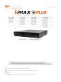
Digital Watchdog DW-VP16xT16P Manuale utente
- Categoria
- Videoregistratori digitali (DVR)
- Tipo
- Manuale utente
Questo manuale è adatto anche per

※ The picture might differ according to the specification and model.
※ Contents of this user manual are protected under copyrights and computer program laws.
Rev: 11/17
Thank You!
Before operating the system, please read this User Manual and retain it for future reference.

WARNING
TO REDUCE FIRE OR SHOCK HAZARD,
DO NOT EXPOSE THE UNIT TO RAIN OR MOISTURE.
The installation should be made by a qualified service
person and conformed to all local codes.

Cautions
Read Before System Operation
Follow these details to prevent material damage or personal injury.
Signs of Caution and Warning
Warning: This sign indicates that the user could die or be seriously wounded if not used or installed properly.
Caution: This sign indicates that the user could be wounded or could expect property damage if not used or installed properly.
Warning: Do not expose the product to fog, rain or too much humid to decrease danger from electric shock or fire.
General Warning
Warning
1. Use the power cord, which is supplied or recommended by the supplier, or it may cause fire.
2. Do not disassemble or reassemble the product. It may cause malfunction or fire.
3. Enquire to your vendor for repair. It may cause electric shock or fire if the repair is not done properly.
4. Do not touch the product with wet hands. It may cause malfunction or electric shock.
5. Product installation must be ensured to a professional for product installation, or it may cause malfunction, electric shock or fire.
6. Ground applies to video products equipped with a 3-wire grounding type plug having a third (grounding) pin. This plug only fits into a grounding-type power outlet. If grounding is not done, it may cause
malfunction or electric shock.
7. Ground connection must not touch gas pipe, water pipe or telephone line. If grounding is not done properly, it may cause electric shock.
8. Prevent metallic foreign substance from going inside the product. It may cause malfunction or electric shock.
9. Do not spray insecticide or flammable spray while driving. It may cause fire.
10. Place the system in a open place where air ventilation is guaranteed, or it may cause over-heating and seriously damage the system to be fired.
11. Prevent water from instilling inside electrical parts. Clean with a dry towel or malfunction or electric shock could result.
Caution
1. Use the power cord, which is supplied or recommended by the supplier. The internal fan rotates at high speed and may cause an accident.
2. Do not drop, give strong vibration, or shock to the product. It may cause malfunction.
3. The air inhaler of the front panel and air outlet of the back panel must not be blocked during installation.
The internal temperature of the product would be greater than allowable and could cause malfunction or fire.
4. Do not touch the product or the power cord when there is thunder. It may cause electric shock.
5. Do not install the product near or on top of heating source. The internal temperature of the product would be greater than allowable and could cause malfunction or fire.
6. Do not install the product on inclined or unstable location or where vibration could be committed. It may cause malfunction.
Cautions about the Power
Warning
1. Must use the outlet of the grounding to connect the power cord, or it may cause fire.
2. Do not connect on the middle of power cord or use extension cord. It may generate heat or cause fire.
3. Do not touch the power cord with wet hands. It may cause electric shock.

4. Keep power cord dry and protect from humidity. It may generate heat or cause fire. The power cord is not waterproof.
5. Hold the body of the plug while removing the power plug. Do not pull the power cord. Damage to the power cord may generate heat or cause fire.
6. Check the power plug regularly. Humidity and moderation in smoking may cause fire.
7. Remove power cord from outlet when product is not used for a long time. It may cause short-circuit or electric shock.
Caution
1. Do not turn off the power by removal of the power plug.
To turn off the power, click the power button from the front panel.
When the system stops abnormally, the power button might not work. Click power button for 5 full seconds to turn power off.
2. Do not cut off the power artificially, or give shock or vibration to unit while the hard disk is activating. It may cause hard disk failure or loss of data.
Remarks
※ Pictures and buttons are subject to be changed or modified up to different models.
※ Function or configuration is subject to be changed or modified without prior notice for improvement of the product.

7 VMAX IP Plus™ User Manual
Table of Contents
1. GETTING STARTED ................................................................................................................................... 8
1.1 CHECKING SUPPLIED ITEMS ........................................................................................................................... 8
1.2 SYSTEM STARTUP .......................................................................................................................................... 9
1.3 SYSTEM SHUTDOWN...................................................................................................................................... 9
1.4 SYSTEM EXPLANATION ................................................................................................................................ 10
2. STARTUP WIZARD ................................................................................................................................... 14
2.1 LANGUAGE ................................................................................................................................................. 14
2.2 DATE /TIME ................................................................................................................................................. 14
2.3 HDD FORMAT ......................................................................................................................................... 15
2.4 NETWORK .................................................................................................................................................. 16
2.5 CAMERA MANAGEMENT ...................................................................................................................... 17
2.6 FINISH ....................................................................................................................................................... 18
3. OPERATION .............................................................................................................................................. 19
3.1 USER LOG-IN .............................................................................................................................................. 19
3.2 CAMERA REGISTRATION .............................................................................................................................. 19
3.3 DELETING CAMERAS ................................................................................................................................... 22
3.4 CAMERA SETUP .......................................................................................................................................... 23
3.5 LIVE DISPLAY MODE ................................................................................................................................... 25
3.6 PTZ OPERATION ......................................................................................................................................... 28
3.7 PLAYBACK RECORDED IMAGES .................................................................................................................... 29
3.8 QUICK BACKUP DURING PLAYBACK .............................................................................................................. 30
3.9 SEARCH RECORDED IMAGE .......................................................................................................................... 31
3.11 DST SETTING AND IMAGE PLAYBACK ........................................................................................................... 36
4. SETTING .................................................................................................................................................... 37
4.1 SYSTEM ..................................................................................................................................................... 38
4.2 DEVICE .................................................................................................................................................... 45
4.3 ALARM ...................................................................................................................................................... 52
4.4 RECORD .................................................................................................................................................. 56
4.5 NETWORK ............................................................................................................................................... 59
4.6 BACKUP .................................................................................................................................................. 69
5. WEB SURVEILLANCE THROUGH INTERNET EXPLORER ............................................................... 71
5.1 WEB LOGIN ................................................................................................................................................ 71
5.2 WEB MONITORING ...................................................................................................................................... 73
5.3 WEB PLAYBACK ......................................................................................................................................... 74
5.4 SETUP ........................................................................................................................................................ 75
6. Q & A .......................................................................................................................................................... 76

VMAX IP Plus™ User Manual 8
1. Getting Started
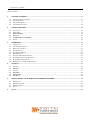
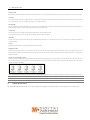
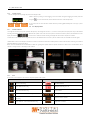
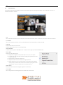
1.1 Checking Supplied Items
Make sure that you have following items supplied with your NVR. If any of these items is missing or damaged, notify your vendor immediately. Keep the packing
utilities for moving or storage purposes afterwards.
Items
Photo
Quantity
Quick Start Guide and Download
Instruction Card
1 Set
48V D/C Adaptor & Power Cable.
* 16CH w/ 16PoE only comes with Power
cable (no D/C adaptor)
1 Set
Rubber Mount
Included contents may differ
depending on the NVR model
1 Set (4 Pieces)
USB Mouse
1 Set

9 VMAX IP Plus™ User Manual
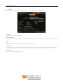
1.2 System Startup
After connecting peripheral devices such as cameras, monitors and a mouse to the NVR, power up the NVR by connecting DC48V adaptor/ power cable to the
power jack on the rear panel. The boot logo will display. Please wait until the boot process completes.
When the system is start, the password change window is displayed. User can set the password whatever user want. Or If user click ‘cancel’ and doesn’t set any
specific password, the default password is empty (No Password). To login, right-click anywhere on the screen and enter the username and password in the popup
screen. There is only one Administrator Account configurable in the NVR. It is assigned with an unchangeable User ID marked as ‘admin’. The default password is
empty (No Password). Administrator account has full access to the NVR and its configurable parameters and can also create new users and to assign rights to the
new user accounts.
If NVR is set as AUTO LOGIN, login process is not necessary.
Caution
1) It may take a few minutes to startup the system after turning on the power, in case the user sets the network configuration as DHCP
mode but under the situation that there is no DHCP server in the network or the network is not connected.
2) The mouse is included. In case you need to replace it, it is highly recommended to choose well-known major brands such as DELL,
MICROSOFT, LOGITECH, or SAMSUNG.
Note
1) Do not forget the administrator’s password that was set for the first time. In case the password is forgot, contact your local dealer for help.
2) Refer to the “Section 4.1.2 User” for AUTO LOGIN and AUTO LOGOFF.
1.3 System Shutdown
To turn off the power, Click exit button [ ] the tool bar and then click [SHUTDOWN] in the pop-up screen as below. Do not pull off the power by pulling the
power plug.
Input the password and click [OK] to shut down the system. Click [YES] to confirm shutdown.
Note
User can input password by virtual keyboard, IR remote-control or front numeric buttons (if available).

User Manual | 10
1.4 System Explanation
1.4.1. Front Panel
** Front panel may differ according to the model.
1.4.2. Power : System ON/OFF
①
Power Button
②
LED Indicator : Indicates system status.(Power, Record and Network status)
③
USB Port : For backup, upgrade and so on.
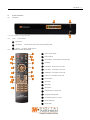
1.4.3. IR Remote Controller (Optional Item)
①
Power : System ON/OFF
②
NVR ID Selection
③
Numeric Button : Channel selection or Password input
④
PTZ Button
⑤
Preset Button : Select Preset in PTZ mode
⑥
Focus Button : Focus IN/OUT in PTZ mode
⑦
ZOOM Button : Zoom IN/OUT in PTZ mode
⑧
Preset Tour : Tour ON/OFF in PTZ mode
⑨
Direction Button
⑩
Enter Button
⑪
Menu Button
⑫
Return Button
⑬
Playback Buttons on Search mode
⑭
Emergency Recording Button
⑮
Auto-Sequence Button in Live mode
⑯
Screen Mode Button
⑰
Backup Button
!
"
#
1
3
8
9
11
6
14
13
2
4
5
12
10
7
17
15
16

11 | VMAX IP Plus™ NVR
Note
User can control multiple NVRs with one IR Remote Controller.
In order to control multiple NVRs, each NVR has different Remote ID.
(The initial ID is set as “0”.)
Note
How to setup the ID # in IR Remote Controller
1) Keep pressing ID selection button (") for about 5 seconds.
2) Set the ID number by pressing numeric button on IR Remote Controller.
ID number is available from 000 up to 255.
3) You have to press numeric button as three-digit number format.
For example, press “000” for 0, “023” for 23, “234” for 234.

User Manual | 12
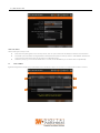
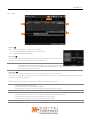
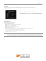
1.4.4. Tool Bar in Live Mode
In live view, move the mouse cursor to the bottom of the screen to show the menu bar.
Menu
Click on the menu button to access the NVR’s main menu screen. See “4. Setting” for details.
Display Mode
Select the display split mode from the available options. Select 1CH, 4CH, 9CH or 16CH mode.
Sequence
Start/stop the sequence mode in live mode. Sequence is disabled if all channels are displayed.
Channel
Switch to single channel view of a specific channel by pressing the corresponding number.
Emergency Recording
The system records all channels with full frame rate at the maximum resolution regardless of recording setting. To stop emergency recording, click the same icon
again.
Backup
Backup recorded video to an external device. See “0 Backup” for details.
Playback
Switch to playback mode. See “3.7 Playback Recorded Image” for details.
Search
Open the search options screen. See “3.6 Search Recorded Image” for details.
Exit
Exit the NVR with three different options: Log Off, Reboot and Shutdown.

13 | VMAX IP Plus™ NVR
Pin
When selected, the NVR’s menu bar will be displayed on the screen permanently, regardless of the mouse’s position.
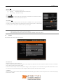
1.4.5. Tool Bar in Playback Mode
In Playback view, move the mouse cursor to the bottom of the screen to show the menu bar.
Channel
Indicates the currently selected channel.
Intelligent Search Bar
Shows recording status for the selected channel from 00:00 to 24:00. A white-vertical line indicates the time currently displayed. Moving the white-vertical line will
update the video.
Previous/Next Date Search
User can move to the previous date or the next date to search.
Playback Controls
: Playback speed control. (x32 / x16 / x8 / x4 / x2).
: Move backward one frame
: Stop button
: Play button
: Move forward one frame
: Playback speed control. (x2 / x4 / x8 / x16 / x32)
: Current playback speed
Screen Display Mode
Select the display split mode from the available options. Select 1CH, 4CH, 9CH or 16CH mode.
Backup
Backup recorded video to an external device. See “0 Backup” for details.
Playback
Switch to playback mode. See “3.7 Playback Recorded Image” for details.
Exit

User Manual | 14
Close playback mode and move to live mode.
Pin
When selected, the NVR’s menu bar will be displayed on the screen permanently, regardless of the mouse’s position.
2. Startup Wizard
When the NVR is launched for the first time, the STARTUP WIZARD will appear. This wizard helps you setup the NVR’s most basic settings for proper functioning.
You can access the Startup Wizard screen at any time by clicking the Startup Wizard [ ] button in setting “MENU>SYSTEM>SETTINGS” menu. (See
“4.1.5 SETTINGS”).
2.1 Language
Select the language according to the country or user’s preference.
If “DISPLAY ON SYSTEM STARTUP” is selected, Startup Wizard will pop up every time the system is started.
2.2 Date/Time
Select the NVR’s date and time format, select the Time Zone, enable or disable daylight savings and sync the NVR with an NTP server or manually enter the date
and time. You can also select to sync the NVR with an NTP server, which will automatically sync your NVR’s date and time settings.

15 | VMAX IP Plus™ NVR
TIME SYNC MODE
There are three types of time sync mode:
§ Server Mode: The operating NVR is set as a Time Sync Server, which can synchronize the time other NVR(s) connected over the same network.
§ Client Mode: Input the IP address of a designated NVR or Remote Software P/C (CMS) as a Time Sync Server in “SYNC SERVER”. The NVR’s time
clock will be synchronized with the server by interval time set in “TIME SYNC CYCLE”.
§ NTP Mode: “pool.ntp.org” is the recommended NTP Server. To activate, set the TIME ZONE of your local area and then click [SYNC NOW].
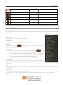
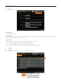
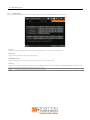
2.3 HDD FORMAT
Digital Watchdog’s NVRs are shipped with pre-installed HDDs that are formatted and ready to be used. There is no need to format the HDDs out of the box.
"
!
#
#

User Manual | 16
HDD FULL (
!
)
Select “Overwrite” or “Stop recording” when HDD is full.
§ Overwrite : NVR deletes oldest data and records new data.
§ Stop recording : NVR stops recording.
HDD CHECK (
"
)
Click ( ) next to each HDD to view full information of each HDD such as model name, serial no,
capacity, bad sector ratio, life time (used time) and temperature.
HDD FORMAT (
#
)
Check the box next to the HDDs you wish to format and press the “FORMAT” button. If system resources are
occupied such as network connection during format process, the format process may fail. It is recommended
to reboot the system to release system resources and then try to format again.
Note
1) It may take a few minutes to format HDD.
2) When the format is done, all data in the HDD will be deleted.
3) The system always reserves some space in each built-in HDD to effectively utilize archiving memory.
2.4 Network
Setup the NVR’s network settings for remote connection.
NETWORK TYPE
Select either STATIC IP or DHCP for dynamic IP.
If DHCP is selected, the NVR will automatically configure the network settings according to the current network requirements. If DHCP is selected, click ‘IP DETECT’
button to detect automatically all the network settings.
If Static IP is selected, manually enter all necessary network settings. For proper configuration, it is recommended to assign the NVR a DHCP address and let it
auto discover all the proper network settings, and then change the Network Type back to Static IP and save the changes
IP ADDRESS
Displays the NVR’s IP address. If DHCP is selected, the IP address will automatically adjust to match the network’s requirements. You can also manually change
the IP address as needed.

17 | VMAX IP Plus™ NVR
SUBNET MASK
Subnet Mask address classifies the subnet that the system belongs to. For more information, please consult your network administrator or your internet provider.
GATEWAY
This is the IP address of the router or gateway server. It is required when connecting to the NVR through the external router over the internet (from another network).
For more information, consult your network administrator or your internet provider.
DNS SERVER
Enter the IP address of the Domain Name Server. You should input the DNS Server information in order to use DDNS, E-mail notifications and NTP Server. For
more information, please consult your network administrator or your internet provider.
TCP/IP PORT
Input the port number to use when connecting to the NVR locally or remotely. Default is 9010.
If your ISP blocks the port # 9010, you need to input another valid port number (ex, 9020).
WEB PORT
Input the port number to use when connecting from the Web Browser. Default is 80. If your ISP blocks the port # 80, you need to input another valid web port
number (ex, 8080).
AUTO IP
Displays the system IP which is assigned through Auto-IP, automatically.
BANDWIDTH LIMIT
Depending on the setting made by user, the system can control the data volume transmitted over network ranging from 25 kbps up to 1Gbps. This function is
effective especially under narrow bandwidth network condition or when user wants to limit “network bandwidth occupied by video transmission” to a certain level.
Default is 100 Mbps
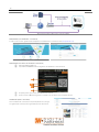
USE UPnP (Universal Plug and Play)
UPnP is a plug-and-play feature that allows the NVR to be automatically discovered by a PC on the same network. To locate the NVR, go to “My Network” on your
PC. The computer will scan your network for all supported devices. The first five characters of the file name of a detected NVR represent the model number,
followed by the NVR’s IP address
Once the PC discovered the NVR, double click on the icon to open the NVR’s web client. Enter your User ID and Password to login and click ‘Connect’ to connect.
Note
The maximum number of simultaneous connection is 15 users.
Note
For the other network settings, such as DDNS, Notification, Mobile Push & P2P Cloud, please refer to the “4.5 Network”.
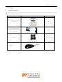
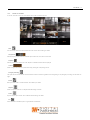
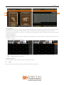
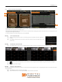
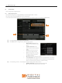
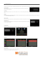
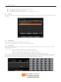
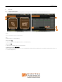
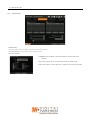
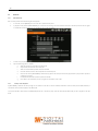
2.5 CAMERA MANAGEMENT
The Camera Management menu allows you to search, register and manage your IP cameras. See “3.2 Camera Registration” for more information.

User Manual | 18
Auto Configuration (1)
The NVR will scan the network for all supported cameras and automatically register them to the available channels. Select the recording mode to apply to all
registered cameras and press [START]. The NVR will search all cameras under the same network (Router) and register them in order, automatically.
In case where there are multiple NVRs on the network, it is recommended to use the Drag & Drop or advanced configuration options to avoid a camera being
connected to multiple NVRs.
Drag & Drop Configuration (2)
The Drag & Drop Configuration scans the network for supported cameras, displaying the results in a table from which you can drag cameras to the viewing channel
to assign them to channels.
① Click [START] button to search camera.
② Select a camera and while clicking on the camera, drag it to a channel to assign it.
③ Click [APPLY] button to finish the process.
Advanced Configuration (3)
Search the network for cameras and manually configure and register them to the NVR.
2.6 Finish
When the Setup Wizard is completed, click “FINISH” to close the wizard and go to the live view screen.
1
2
3

19 | VMAX IP Plus™ NVR
3. Operation
3.1 User Log-in
Input USER and PASSWORD after turning on the system. The factory default of USER and PASSWORD are “admin” and no password.
Note
1) LOGIN window will be permanently displayed until a user logs in with the right USER and password.
2) If NVR is set as AUTO LOGIN, login process is not necessary. See “4.1.2 User” for more information.
Note
The key in the virtual keyboard includes common words, such as Admin, root, http://, rtsp://, www., .com, .net, .org etc.
3.2 Camera Registration
The NVR can connect to any ONVIF® IP cameras over the network. If the cameras are connected to the PoE switch in the back of the NVR, the cameras will also
receive power and transmit data to and from the NVR.
3.2.1. PoE Camera Connection
PoE cameras are automatically connected when the camera is plugged to the PoE port. Channels assigned to cameras connected to the NVR’s PoE switch will
display the channel title in green.
Cameras connected to the NVR’s PoE switch must be set to ‘DHCP’ before connecting to the NVR.
For cameras that support ‘Auto IP’, the NVR will automatically control its IP settings.
Note
If PoE camera is connected to the PoE channel while another camera is being assigned to that channel, the previously assigned camera moves to
another channel and the PoE camera will be assigned to that channel.
Note
Zero-Configuration
It is the Link-Local IP address assignment method through Auto-IP and it is for assigning IP, automatically, when the DHCP is not
available or supported. The device that adopts this technology selects 169.254.xxx.xxx, in general, and assign the IP address after
checking the availability of the selected IP address

User Manual | 20
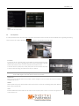
3.2.2. Camera Connection through Network
The NVR supports three ways to search and register cameras to the NVR. The AUTO CONFIGURATION option allows the NVR to scan the network and automatically
register the first cameras it finds to the available channels.
The DRAG & DROP CONFIGURATION option scans the network for supported cameras, displaying the results in a table from which you can drag cameras to the
viewing channel to assign them to channels.
For advanced settings and manually adding cameras, select ADVANCED.
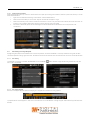
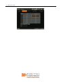
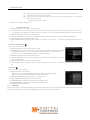
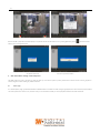
3.2.2.1. AUTO CONFIGURATION
① Select a recording mode for the cameras. This recording option will be applied to all cameras registered to
the NVR.
② Click [START]. The NVR will search all cameras under the same network (subnet) and register them in order,
automatically.
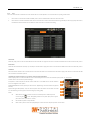
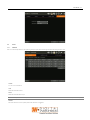
3.2.2.2. DRAG&DROP CONFIGURATION
① Click [START] button to search camera. The NVR will search the network for cameras and display all results in the table on the right.
② Select camera in the list and drag and drop it to the channel you want to assign to the camera. (While moving, the mouse pointer is changed to
.)
③ Click [APPLY] to save all changes.
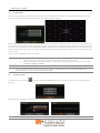
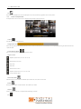
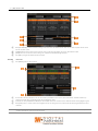
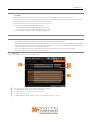
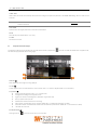
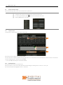
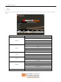
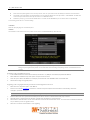
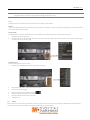
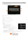
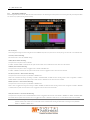
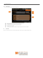
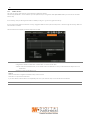
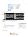
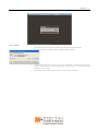
3.2.2.3. ADVANCE CONFIGURATION
The Advanced Configuration menu allows you to search for cameras with advanced configuration options, manage assigned cameras and manually add cameras
using individual URLs.
① Click [SEARCH] to search all cameras on the network.
② Select a camera from the list and click [GET STREAM] to read the streams of the camera.
1
5
2

21 | VMAX IP Plus™ NVR
③ When [GET STREAM] is selected, the NVR will assign a channel number to the selected camera. User can also select a specific channel number
from the drop-down options.
④ [CAMERA INFO] shows the camera’s basic information such as model name, IP address, Port number, Mac address in detail.
⑤ [SETUP] allows user to control the camera’s setting such as Resolution/Frame/Bitrate/Image Quality etc.
⑥ Click [APPLY] to register the selected camera to the NVR.
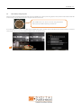
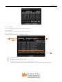
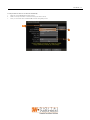
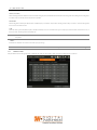
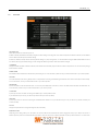
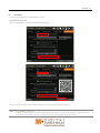
3.2.2.4. Multi Select
① Click [SEARCH] button to search cameras.
② Once all search results are displayed, user can sort the table by the different columns such as protocol, IP Address, Hardware and Name, by
clicking each property tabs. The selected property will be highlighted in yellow.
③ Check the box next to [CAMERA MULTI SELECT] to select multiple cameras from the search results. Selected cameras will be highlighted in green.
④ When [APPLY] button is clicked, cameras will be registered one by one starting from the top. Cameras that are already registered will be shown as
unselected.
Note
During the registration process of Camera Multi Select, if there is a camera which has a different IP range or requires ID & Password, the process is
paused and the NVR will request the required information.
!
"
%
"
#
&
'
"
#
'
!

User Manual | 22
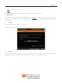
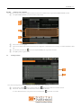
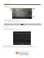
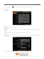
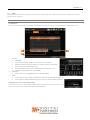
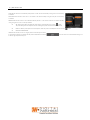
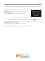
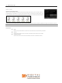
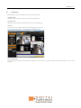
3.2.2.5. MANUALLY ADD CAMERAS
If a user wants to connect to an IP camera in a different network, the cameras can be added manually using the [ADD CAMERAS MANUALLY] button.
① Click [ADD CAMERAS MANUALLY] to open the camera property window.
② Select channel number to register.
③ Select protocol (ONVIF, RTSP, FOCUS and VHT) of the camera. Registration is available with one of the following. – IP Address, RTSP URL or ONVIF
URL
④ Input necessary information with button and click [GET STREAM] button to get streams information.
⑤ Click [APPLY] button to register camera.
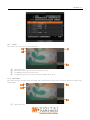
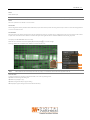
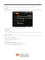
3.3 Deleting Cameras
Go to Advanced Configuration by clicking [ADVANCED] in Camera Management (Menu > Record).
① Non-PoE Camera - Delete ( ) button is always activated. Click of the camera to delete it from the NVR’s channels.
② PoE Camera - PoE cameras cannot be deleted while connected to the NVR’s PoE switch.
In order to delete a PoE camera, unplug the camera from the NVR and click button when it is activated.
"
#
'
'
%
"
!
La pagina si sta caricando...
La pagina si sta caricando...
La pagina si sta caricando...
La pagina si sta caricando...
La pagina si sta caricando...
La pagina si sta caricando...
La pagina si sta caricando...
La pagina si sta caricando...
La pagina si sta caricando...
La pagina si sta caricando...
La pagina si sta caricando...
La pagina si sta caricando...
La pagina si sta caricando...
La pagina si sta caricando...
La pagina si sta caricando...
La pagina si sta caricando...
La pagina si sta caricando...
La pagina si sta caricando...
La pagina si sta caricando...
La pagina si sta caricando...
La pagina si sta caricando...
La pagina si sta caricando...
La pagina si sta caricando...
La pagina si sta caricando...
La pagina si sta caricando...
La pagina si sta caricando...
La pagina si sta caricando...
La pagina si sta caricando...
La pagina si sta caricando...
La pagina si sta caricando...
La pagina si sta caricando...
La pagina si sta caricando...
La pagina si sta caricando...
La pagina si sta caricando...
La pagina si sta caricando...
La pagina si sta caricando...
La pagina si sta caricando...
La pagina si sta caricando...
La pagina si sta caricando...
La pagina si sta caricando...
La pagina si sta caricando...
La pagina si sta caricando...
La pagina si sta caricando...
La pagina si sta caricando...
La pagina si sta caricando...
La pagina si sta caricando...
La pagina si sta caricando...
La pagina si sta caricando...
La pagina si sta caricando...
La pagina si sta caricando...
La pagina si sta caricando...
La pagina si sta caricando...
La pagina si sta caricando...
La pagina si sta caricando...
La pagina si sta caricando...
-
 1
1
-
 2
2
-
 3
3
-
 4
4
-
 5
5
-
 6
6
-
 7
7
-
 8
8
-
 9
9
-
 10
10
-
 11
11
-
 12
12
-
 13
13
-
 14
14
-
 15
15
-
 16
16
-
 17
17
-
 18
18
-
 19
19
-
 20
20
-
 21
21
-
 22
22
-
 23
23
-
 24
24
-
 25
25
-
 26
26
-
 27
27
-
 28
28
-
 29
29
-
 30
30
-
 31
31
-
 32
32
-
 33
33
-
 34
34
-
 35
35
-
 36
36
-
 37
37
-
 38
38
-
 39
39
-
 40
40
-
 41
41
-
 42
42
-
 43
43
-
 44
44
-
 45
45
-
 46
46
-
 47
47
-
 48
48
-
 49
49
-
 50
50
-
 51
51
-
 52
52
-
 53
53
-
 54
54
-
 55
55
-
 56
56
-
 57
57
-
 58
58
-
 59
59
-
 60
60
-
 61
61
-
 62
62
-
 63
63
-
 64
64
-
 65
65
-
 66
66
-
 67
67
-
 68
68
-
 69
69
-
 70
70
-
 71
71
-
 72
72
-
 73
73
-
 74
74
-
 75
75


Digital Watchdog DW-VP16xT16P Manuale utente
- Categoria
- Videoregistratori digitali (DVR)
- Tipo
- Manuale utente
- Questo manuale è adatto anche per
in altre lingue
Altri documenti
-
Elvox 46241.F08 Manuale utente
-
-
-
Buffalo HD-PZN1.0U3B Guida utente
-
Trendnet TV-NVR1508 Guida utente
-
Eizo FDF2304W-IP Manuale del proprietario
-
Risco VUpoint RVNVR040020 Guida d'installazione
-
-
Axis AXIS Q8108-R Manuale utente
-