GYS PROMIG 400 G DV Manuale utente
- Categoria
- Sistema di saldatura
- Tipo
- Manuale utente
Questo manuale è adatto anche per

FR
EN
DE
ES
RU
75559 - V14 - 28/10/19
2-7 / 44-60
TRIMIG 200-4S
TRIMIG 250-4S.DV
TRIMIG 300-4S
8-13 / 44-60
14-19 / 44-60
20-25 / 44-60
26-31 / 44-60
www.gys.fr
NL
IT
32-37 / 44-60
38-43 / 44-60

2
TRIMIG 200-4S / 250-4S.DV / 300-4S
FR
Notice originale
2
AVERTISSEMENTS - RÈGLES DE SÉCURITÉ
CONSIGNE GÉNÉRALE
Ces instructions doivent être lues et bien comprises avant toute opération.
Toute modication ou maintenance non indiquée dans le manuel ne doit pas être entreprise.
Tout dommage corporel ou matériel dû à une utilisation non-conforme aux instructions de ce manuel ne pourra être retenu à la charge du fabricant.
En cas de problème ou d’incertitude, consulter une personne qualiée pour manier correctement l’installation.
ENVIRONNEMENT
Ce matériel doit être utilisé uniquement pour faire des opérations de soudage dans les limites indiquées par la plaque signalétique et/ou le manuel.
Il faut respecter les directives relatives à la sécurité. En cas d’utilisation inadéquate ou dangereuse, le fabricant ne pourra être tenu responsable.
L’installation doit être utilisée dans un local sans poussière, ni acide, ni gaz inammable ou autres substances corrosives de même pour son stockage.
S’assurer d’une circulation d’air lors de l’utilisation.
Plages de température :
Utilisation entre -10 et +40°C (+14 et +104°F).
Stockage entre -20 et +55°C (-4 et 131°F).
Humidité de l’air :
Inférieur ou égal à 50% à 40°C (104°F).
Inférieur ou égal à 90% à 20°C (68°F).
Altitude :
Jusqu’à 1000 m au-dessus du niveau de la mer (3280 pieds).
PROTECTIONS INDIVIDUELLE ET DES AUTRES
Le soudage à l’arc peut être dangereux et causer des blessures graves voire mortelles.
Le soudage expose les individus à une source dangereuse de chaleur, de rayonnement lumineux de l’arc, de champs électromagnétiques (attention
au porteur de pacemaker), de risque d’électrocution, de bruit et d’émanations gazeuses.
Pour bien se protéger et protéger les autres, respecter les instructions de sécurité suivantes :
An de se protéger de brûlures et rayonnements, porter des vêtements sans revers, isolants, secs, ignifugés et en bon état, qui
couvrent l’ensemble du corps.
Utiliser des gants qui garantissent l’isolation électrique et thermique.
Utiliser une protection de soudage et/ou une cagoule de soudage d’un niveau de protection sufsant (variable selon les applica-
tions). Protéger les yeux lors des opérations de nettoyage. Les lentilles de contact sont particulièrement proscrites
Il est parfois nécessaire de délimiter les zones par des rideaux ignifugés pour protéger la zone de soudage des rayons de l’arc, des
projections et des déchets incandescents.
Informer les personnes dans la zone de soudage de ne pas xer les rayons de l’arc ni les pièces en fusion et de porter les vêtements
adéquats pour se protéger.
Utiliser un casque contre le bruit si le procédé de soudage atteint un niveau de bruit supérieur à la limite autorisée (de même pour
toute personne étant dans la zone de soudage).
Tenir à distance des parties mobiles (ventilateur) les mains, cheveux, vêtements.
Ne jamais enlever les protections carter du groupe froid lorsque la source de courant de soudage est sous tension, le fabricant ne
pourrait être tenu pour responsable en cas d’accident.
Les pièces qui viennent d’être soudées sont chaudes et peuvent provoquer des brûlures lors de leur manipulation. Lors d’interven-
tion d’entretien sur la torche ou le porte-électrode, il faut s’assurer que celui-ci soit sufsamment froid en attendant au moins 10
minutes avant toute intervention. Le groupe froid doit être allumé lors de l’utilisation d’une torche refroidie eau an d’être sûr que
le liquide ne puisse pas causer de brûlures.
Il est important de sécuriser la zone de travail avant de la quitter an de protéger les personnes et les biens.
FUMÉES DE SOUDAGE ET GAZ
Les fumées, gaz et poussières émis par le soudage sont dangereux pour la santé. Il faut prévoir une ventilation sufsante, un
apport d’air est parfois nécessaire. Un masque à air frais peut être une solution en cas d’aération insufsante.
Vérier que l’aspiration est efcace en la contrôlant par rapport aux normes de sécurité.

3
TRIMIG 200-4S / 250-4S.DV / 300-4S
FR
Notice originale
3
Attention le soudage dans des milieux de petites dimensions nécessite une surveillance à distance de sécurité. Par ailleurs le soudage de certains
matériaux contenant du plomb, cadmium, zinc ou mercure voire du béryllium peuvent être particulièrement nocifs, dégraisser également les pièces
avant de les souder.
Les bouteilles doivent être entreposées dans des locaux ouverts ou bien aérés. Elles doivent être en position verticale et maintenues à un support ou
sur un chariot.
Le soudage doit être proscrit à proximité de graisse ou de peinture.
RISQUES DE FEU ET D’EXPLOSION
Protéger entièrement la zone de soudage, les matières inammables doivent être éloignées d’au moins 11 mètres.
Un équipement anti-feu doit être présent à proximité des opérations de soudage.
Attention aux projections de matières chaudes ou d’étincelles et même à travers des ssures, elles peuvent être source d’incendie ou d’explosion.
Éloigner les personnes, les objets inammables et les containers sous pressions à une distance de sécurité sufsante.
Le soudage dans des containers ou des tubes fermés est à proscrire et dans le cas où ils sont ouverts il faut les vider de toute matière inammable
ou explosive (huile, carburant, résidus de gaz …).
Les opérations de meulage ne doivent pas être dirigées vers la source de courant de soudage ou vers des matières inammables.
BOUTEILLES DE GAZ
Le gaz sortant des bouteilles peut être source de suffocation en cas de concentration dans l’espace de soudage (bien ventiler).
Le transport doit être fait en toute sécurité : bouteilles fermées et la source de courant de soudage éteinte. Elles doivent être
entreposées verticalement et maintenues par un support pour limiter le risque de chute.
Fermer la bouteille entre deux utilisations. Attention aux variations de température et aux expositions au soleil.
La bouteille ne doit pas être en contact avec une amme, un arc électrique, une torche, une pince de masse ou toutes autres
sources de chaleur ou d’incandescence.
Veiller à la tenir éloignée des circuits électriques et de soudage et donc ne jamais souder une bouteille sous pression.
Attention lors de l’ouverture du robinet de la bouteille, il faut éloigner la tête la robinetterie et s’assurer que le gaz utilisé est
approprié au procédé de soudage.
SÉCURITÉ ÉLECTRIQUE
Le réseau électrique utilisé doit impérativement avoir une mise à la terre. Utiliser la taille de fusible recommandée sur le tableau
signalétique.
Une décharge électrique peut être une source d’accident grave direct ou indirect, voire mortel.
Ne jamais toucher les parties sous tension à l’intérieur comme à l’extérieur de la source de courant sous-tension (Torches, pinces, câbles, électrodes)
car celles-ci sont branchées au circuit de soudage.
Avant d’ouvrir la source de courant de soudage, il faut la déconnecter du réseau et attendre 2 minutes. an que l’ensemble des condensateurs soit
déchargé.
Ne pas toucher en même temps la torche ou le porte-électrode et la pince de masse.
Veiller à changer les câbles, torches si ces derniers sont endommagés, par des personnes qualiées et habilitées. Dimensionner la section des câbles
en fonction de l’application. Toujours utiliser des vêtements secs et en bon état pour s’isoler du circuit de soudage. Porter des chaussures isolantes,
quel que soit le milieu de travail.
CLASSIFICATION CEM DU MATÉRIEL
Ce matériel de Classe A n’est pas prévu pour être utilisé dans un site résidentiel où le courant électrique est fourni par le réseau
public d’alimentation basse tension. Il peut y avoir des difcultés potentielles pour assurer la compatibilité électromagnétique
dans ces sites, à cause des perturbations conduites, aussi bien que rayonnées à fréquence radioélectrique.
Trimig 200-4S :
Ce matériel est conforme à la CEI 61000-3-12, à condition que la puissance de court-circuit Ssc soit supérieure ou égale à
2.8 MVA au point d’interface entre l’alimentation de l’utilisateur et le réseau public de distribution. Il est de la responsabilité de
l’installateur ou de l’utilisateur du matériel de s’assurer, si nécessaire en consultant l’exploitant du réseau de distribution, que le
matériel est raccordé uniquement à une alimentation ayant une puissance de court-circuit Ssc supérieure ou égale à 2.8 MVA.
Trimig 250-4S DV-230/400V et Trimig 300-4S :
Ce matériel est conforme à la CEI 61000-3-12, à condition que la puissance de court-circuit Ssc soit supérieure ou égale à
3.9 MVA au point d’interface entre l’alimentation de l’utilisateur et le réseau public de distribution. Il est de la responsabilité de
l’installateur ou de l’utilisateur du matériel de s’assurer, si nécessaire en consultant l’exploitant du réseau de distribution, que le
matériel est raccordé uniquement à une alimentation ayant une puissance de court-circuit Ssc supérieure ou égale à 3.9 MVA.
Ce matériel est conforme à la CEI 61000-3-11.
ÉMISSIONS ÉLECTROMAGNÉTIQUES
Le courant électrique passant à travers n’importe quel conducteur produit des champs électriques et magnétiques (EMF) loca-
lisés. Le courant de soudage produit un champ électromagnétique autour du circuit de soudage et du matériel de soudage.

4
TRIMIG 200-4S / 250-4S.DV / 300-4S
FR
Notice originale
4
Les champs électromagnétiques EMF peuvent perturber certains implants médicaux, par exemple les stimulateurs cardiaques. Des mesures de
protection doivent être prises pour les personnes portant des implants médicaux. Par exemple, restrictions d’accès pour les passants ou une évaluation
de risque individuelle pour les soudeurs.
Tous les soudeurs devraient utiliser les procédures suivantes an de minimiser l’exposition aux champs électromagnétiques provenant du circuit de
soudage:
• positionner les câbles de soudage ensemble – les xer les avec une attache, si possible;
• se positionner (torse et tête) aussi loin que possible du circuit de soudage;
• ne jamais enrouler les câbles de soudage autour du corps;
• ne pas positionner le corps entre les câbles de soudage. Tenir les deux câbles de soudage sur le même côté du corps;
• raccorder le câble de retour à la pièce mise en œuvre aussi proche que possible à la zone à souder;
• ne pas travailler à côté de la source de courant de soudage, ne pas s’assoir dessus ou ne pas s’y adosser ;
• ne pas souder lors du transport de la source de courant de soudage ou le dévidoir.
Les porteurs de stimulateurs cardiaques doivent consulter un médecin avant d’utiliser ce matériel.
L’exposition aux champs électromagnétiques lors du soudage peut avoir d’autres effets sur la santé que l’on ne connaît pas
encore
DES RECOMMANDATIONS POUR ÉVALUER LA ZONE ET L’INSTALLATION DE SOUDAGE
Généralités
L’utilisateur est responsable de l’installation et de l’utilisation du matériel de soudage à l’arc suivant les instructions du fabricant. Si des perturbations
électromagnétiques sont détectées, il doit être de la responsabilité de l’utilisateur du matériel de soudage à l’arc de résoudre la situation avec
l’assistance technique du fabricant. Dans certains cas, cette action corrective peut être aussi simple qu’une mise à la terre du circuit de soudage. Dans
d’autres cas, il peut être nécessaire de construire un écran électromagnétique autour de la source de courant de soudage et de la pièce entière avec
montage de ltres d’entrée. Dans tous les cas, les perturbations électromagnétiques doivent être réduites jusqu’à ce qu’elles ne soient plus gênantes.
Évaluation de la zone de soudage
Avant d’installer un matériel de soudage à l’arc, l’utilisateur doit évaluer les problèmes électromagnétiques potentiels dans la zone environnante. Ce qui
suit doit être pris en compte:
a) la présence au-dessus, au-dessous et à côté du matériel de soudage à l’arc d’autres câbles d’alimentation, de commande, de signalisation et de
téléphone;
b) des récepteurs et transmetteurs de radio et télévision;
c) des ordinateurs et autres matériels de commande;
d) du matériel critique de sécurité, par exemple, protection de matériel industriel;
e) la santé des personnes voisines, par exemple, emploi de stimulateurs cardiaques ou d’appareils contre la surdité;
f) du matériel utilisé pour l’étalonnage ou la mesure;
g) l’immunité des autres matériels présents dans l’environnement.
L’utilisateur doit s’assurer que les autres matériels utilisés dans l’environnement sont compatibles. Cela peut exiger des mesures de protection
supplémentaires;
h) l’heure du jour où le soudage ou d’autres activités sont à exécuter.
La dimension de la zone environnante à prendre en compte dépend de la structure du bâtiment et des autres activités qui s’y déroulent. La zone
environnante peut s’étendre au-delà des limites des installations.
Évaluation de l’installation de soudage
Outre l’évaluation de la zone, l’évaluation des installations de soudage à l’arc peut servir à déterminer et résoudre les cas de perturbations. Il convient
que l’évaluation des émissions comprenne des mesures in situ comme cela est spécié à l’Article 10 de la CISPR 11:2009. Les mesures in situ peuvent
également permettre de conrmer l’efcacité des mesures d’atténuation.
RECOMMANDATION SUR LES MÉTHODES DE RÉDUCTION DES ÉMISSIONS ÉLECTROMAGNÉTIQUES
a. Réseau public d’alimentation: Il convient de raccorder le matériel de soudage à l’arc au réseau public d’alimentation selon les recommandations
du fabricant. Si des interférences se produisent, il peut être nécessaire de prendre des mesures de prévention supplémentaires telles que le ltrage du
réseau public d’alimentation. Il convient d’envisager de blinder le câble d’alimentation dans un conduit métallique ou équivalent d’un matériel de soudage
à l’arc installé à demeure. Il convient d’assurer la continuité électrique du blindage sur toute sa longueur. Il convient de raccorder le blindage à la source
de courant de soudage pour assurer un bon contact électrique entre le conduit et l’enveloppe de la source de courant de soudage.
b. Maintenance du matériel de soudage à l’arc : Il convient que le matériel de soudage à l’arc soit soumis à l’entretien de routine suivant les
recommandations du fabricant. Il convient que tous les accès, portes de service et capots soient fermés et correctement verrouillés lorsque le matériel
de soudage à l’arc est en service. Il convient que le matériel de soudage à l’arc ne soit modié en aucune façon, hormis les modications et réglages
mentionnés dans les instructions du fabricant. Il convient, en particulier, que l’éclateur d’arc des dispositifs d’amorçage et de stabilisation d’arc soit réglé
et entretenu suivant les recommandations du fabricant.
c. Câbles de soudage : Il convient que les câbles soient aussi courts que possible, placés l’un près de l’autre à proximité du sol ou sur le sol.
d. Liaison équipotentielle : Il convient d’envisager la liaison de tous les objets métalliques de la zone environnante. Toutefois, des objets métalliques
reliés à la pièce à souder accroissent le risque pour l’opérateur de chocs électriques s’il touche à la fois ces éléments métalliques et l’électrode. Il convient
d’isoler l’opérateur de tels objets métalliques.
e. Mise à la terre de la pièce à souder : Lorsque la pièce à souder n’est pas reliée à la terre pour la sécurité électrique ou en raison de ses
dimensions et de son emplacement, ce qui est le cas, par exemple, des coques de navire ou des charpentes métalliques de bâtiments, une connexion
raccordant la pièce à la terre peut, dans certains cas et non systématiquement, réduire les émissions. Il convient de veiller à éviter la mise à la terre des
pièces qui pourrait accroître les risques de blessure pour les utilisateurs ou endommager d’autres matériels électriques. Si nécessaire, il convient que le
raccordement de la pièce à souder à la terre soit fait directement, mais dans certains pays n’autorisant pas cette connexion directe, il convient que la
connexion soit faite avec un condensateur approprié choisi en fonction des réglementations nationales.
f. Protection et blindage : La protection et le blindage sélectifs d’autres câbles et matériels dans la zone environnante peuvent limiter les problèmes
de perturbation. La protection de toute la zone de soudage peut être envisagée pour des applications spéciales.

5
TRIMIG 200-4S / 250-4S.DV / 300-4S
FR
Notice originale
5
TRANSPORT ET TRANSIT DE LA SOURCE DE COURANT DE SOUDAGE
Ne pas utiliser les câbles ou torche pour déplacer la source de courant de soudage. Elle doit être déplacée en position verticale.
Ne pas faire transiter la source de courant au-dessus de personnes ou d’objets.
Ne jamais soulever une bouteille de gaz et la source de courant en même temps. Leurs normes de transport sont distinctes.
Il est préférable d’enlever la bobine de l avant tout levage ou transport de la source de courant de soudage.
Les courants de soudage vagabonds peuvent détruire les conducteurs de terre, endommager l’équipement et les dispositifs électriques
et causer des échauffements de composants pouvant entrainer un incendie.
- Toutes les connexions de soudages doivent être connectées fermement, vérier régulièrement !
- S’assurer que la xation de la pièce est solide et sans problèmes électriques !
- Attacher ou suspendre tous les éléments conducteurs d’électricité de la source de soudage comme le châssis, le chariot et les systèmes de levage
pour qu’ils soient isolés !
- Ne pas déposer d’autres équipements comme des perceuses, dispositifs d’affutage, etc sur la source de soudage, le chariot, ou les systèmes de
levage sans qu’ils soient isolés !
- Toujours déposer les torches de soudage ou portes électrodes sur une surface isolée quand ils ne sont pas utilisés !
INSTALLATION DU MATÉRIEL
• Mettre la source de courant de soudage sur un sol dont l’inclinaison maximum est de 10°.
• Prévoir une zone sufsante pour aérer la source de courant de soudage et accéder aux commandes.
• Ne pas utiliser dans un environnement comportant des poussières métalliques conductrices.
• La source de courant de soudage doit être à l’abri de la pluie battante et ne pas être exposée aux rayons du soleil.
• Le matériel est de degré de protection IP21, signiant :
- une protection contre l’accès aux parties dangereuses des corps solides de diam >12.5 mm et,
- une protection contre les chutes verticales de gouttes d’eau
Les câbles d’alimentation, de rallonge et de soudage doivent être totalement déroulés an d’éviter toute surchauffe.
Le fabricant n’assume aucune responsabilité concernant les dommages provoqués à des personnes et objets dus à une utilisation
incorrecte et dangereuse de ce matériel.
ENTRETIEN / CONSEILS
• L’entretien ne doit être effectué que par une personne qualiée. Un entretien annuel est conseillé.
• Couper l’alimentation en débranchant la prise, et attendre deux minutes avant de travailler sur le matériel. A l’intérieur, les
tensions et intensités sont élevées et dangereuses.
• Régulièrement, enlever le capot et dépoussiérer à la soufette. En proter pour faire vérier la tenue des connexions électriques
avec un outil isolé par un personnel qualié.
• Contrôler régulièrement l’état du cordon d’alimentation. Si le câble d’alimentation est endommagé, il doit être remplacé par le
fabricant, son service après-vente ou une personne de qualication similaire, an d’éviter tout danger.
• Laisser les ouïes de la source de courant de soudage libres pour l’entrée et la sortie d’air.
• Ne pas utiliser cette source de courant de soudage pour dégeler des canalisations, recharger des batteries/accumulateurs ou
démarrer des moteurs.
INSTALLATION – FONCTIONNEMENT PRODUIT
Il est recommandé d’utiliser les câbles de soudage fournis avec l’appareil an d’obtenir les réglages optimum du produit.
DESCRIPTION
Merci de votre choix ! An de tirer le maximum de satisfaction de votre poste, veuillez lire avec attention ce qui suit :
Les TRIMIG sont des postes de soudure semi-automatique « synergic » sur roues, ventilés pour le soudage (MIG ou MAG). Ils sont recommandés
pour le soudage des aciers, des inox, des aluminiums. Leur réglage est simple et rapide grâce à leur fonction « vitesse de l synergique ». Ils fonc-
tionnent sur une alimentation 400 V triphasée ou 230 V triphasée pour les modèles DV.
ALIMENTATION ÉLECTRIQUE
Ce matériel est livré avec prise 16 A de type EN 60309-1 et doit être branché à une installation électrique triphasée 400 V (50-60 Hz) à quatre ls
avec le neutre relié à la terre.
Le courant effectif absorbé (I1eff) est indiqué sur le matériel, pour les conditions d’utilisation maximales. Vérier que l’alimentation et ses protections
(fusible et/ou disjoncteur) sont compatibles avec le courant nécessaire en utilisation. Dans certains pays, il peut être nécessaire de changer la prise
pour permettre une utilisation aux conditions maximales. L'appareil doit être placé de façon telle que la che de prise de courant soit accessible. Ne
pas utiliser de rallonge ayant une section inférieure à 4 mm². Ces appareils sont livrés avec une prise 16 A de type CEE 7/7. Les TRIMIG doivent être
reliés à une prise 400 V 3 Ph. AVEC terre protégée par un disjoncteur 16 A et un différentiel 30 mA.
Alimentation 230 V triphasée du Trimig 250-4S DV :
ATTENTION : ces appareils sont pré-monté en usine en 400 V triphasée. Si votre installation électrique est en 230 V triphasée, veuillez modier le
branchement de la plaque à bornes à l’intérieur du poste. Cette manipulation doit être effectuée par une personne compétente. Pour ce faire, se
référer au schéma de branchement 230 V situé à l’intérieur du poste. L’alimentation électrique doit être protégée par un disjoncteur 16 A et un dif-
férentiel 30 mA.

6
TRIMIG 200-4S / 250-4S.DV / 300-4S
FR
Notice originale
6
DESCRIPTION DU POSTE (FIG-II PAGE 46)
1- Interrupteur marche – arrêt
2- Commutateur de réglage de tension
3- Clavier de réglages des paramètres de soudage (mode manuel ou
automatique).
4- Raccord torche au standard européen.
5- Voyant de protection thermique sur le clavier de commande : signale
une coupure thermique lorsque l’appareil est utilisé de façon intensive
(coupure de plusieurs minutes).
6- Support torches avant
7- Câble d’alimentation
8- Sortie pince de masse.
9- Support bouteille
(TRIMIG 200-4S=4m
3
/ TRIMIG 250-4S & 330-4S=10m
3
).
10- Chaine de xation pour bouteille.
Attention : bien xer la bouteille cf. FIG-IV-1
11- Support bobine Ø 200/300 mm.
12- Entrée gaz 1.
13- Support cables arrière.
14- Câble d’invertion de polarité (TRIMIG 300-4S)
SOUDAGE SEMI-AUTOMATIQUE EN ACIER/INOX (MODE MAG) (FIG-III)
Le TRIMIG 200-4S peut souder du l acier et inox de Ø 0,6/0,8 et 1 mm. (FIG-III-A) L’appareil est livré d’origine pour fonctionner avec du l Ø 1,0 mm
en acier (tube contact Ø 1.0, galets Ø 0,8/1,0 : réf. 042360). Lors de l’utilisation du l de diamètre inférieur ; il convient de changer le tube contact. Le
galet du moto-dévidoir est un galet réversible. Le positionner de telle façon à lire le chiffre souhaité sur le anc visible du galet (Ø 0,6/0,8 : réf. 042353).
Le TRIMIG 250-4S DV 230-400V peut souder du l acier et inox de 0,8/1 et 1,2. Il est livré d’origine pour fonctionner avec du l Ø 1,0 mm en acier
(galets Ø 0,8/1,0 : réf. 042360). Les Trimig 300-4S peuvent souder du l acier et inox de 0,8/1 et 1,2. Ils sont livrés d’origine pour fonctionner avec
du l Ø 1 mm en acier (galets Ø 1,0/1,2 : réf. 046849). L’utilisation en acier ou inox nécessite un gaz spécique au soudage argon + CO2 (Ar + CO2 ).
La proportion de CO2 varie selon l’utilisation. Pour le choix du gaz, demander conseil à un distributeur de gaz. Le débit de gaz en acier se situe entre
10 et 20 l/min selon l’environnement et l’expérience du soudeur.
SOUDAGE SEMI-AUTOMATIQUE ALUMINIUM (FIG-III)
Le TRIMIG 200-4S peut souder du l aluminium de Ø 0,8 et 1 mm. (FIG-III-B) Les TRIMIG 250 et 300 peuvent souder du l aluminium de Ø 1 mm et
1,2 mm. (FIG-III-B) Pour souder l’aluminium, il faut utiliser un gaz neutre: argon pur (Ar). Pour le choix du gaz, demander conseil à un distributeur
de gaz. Le débit du gaz se situe entre 15 et 25 l/min selon l’environnement et l’expérience du soudeur.
Ci-dessous les différences entre l’utilisation soudage acier et soudage aluminium :
• La pression des galets presseurs du moto-dévidoir sur le l : mettre un minimum de pression an de ne pas écraser le l.
• Tube capillaire : retirer le tube capillaire avant de connecter la torche aluminium avec une gaine en téon.
• Torche : utiliser une torche spéciale aluminium. Cette torche possède une gaine téon an de réduire les frottements.
• NE PAS couper la Gaine au bord du raccord ! cette gaine sert à guider le l à partir des galets. (FIG-III-B)
• Tube contact : utiliser un tube contact SPECIAL aluminium correspondant au diamètre du l.
• Galets Ø 0,8/1,0 : réf. 042377 et galets Ø 1,0/1,2 : réf. 040915.
SOUDAGE SEMI-AUTOMATIQUE DES ACIERS À HAUTE LIMITE ÉLASTIQUE
Le TRIMIG 200-4S peut soudobraser les tôles à haute limite élastique (THLE) avec un l en cuprosilicium (CuSi3) ou en cuproaluminium (CuAl8) (ø
0,8 et ø 0,1 mm). Le soudeur doit utiliser un gaz neutre: argon pur (Ar). Pour le choix du gaz, demander conseil à un distributeur de gaz. Le débit
du gaz se situe entre 15 et 25 L/min.
SOUDAGE FIL « NO GAS »
Le TRIMIG 300-4S peut souder du l « No Gas » à condition d’inverser la polarité (FIG-VIII - couple de serrage maximum de 5 Nm).
Souder du l fourré avec une buse standard peut entraîner une surchauffe et la détérioration de la torche. Enlever la buse d’origine (FIG-VII).
• Galets Ø 0,9/1,2 : réf. 042407.
PROCÉDURE DE MONTAGE DES BOBINES ET DES TORCHES (FIG-IV PAGE 47)
Ouvrir la trappe du poste.
• Positionner la bobine en tenant compte de l’ergot d’entrainement (3) du support bobine. Pour monter une bobine de 200mm, installer au préalable
un adaptateur sur le support (ref. 042889).
• Régler le frein de la bobine (4) pour éviter lors de l’arrêt de la soudure que l’inertie de la bobine n’emmêle le l. De manière générale, ne pas serrer
trop fort ! Serrer ensuite la vis de maintien (2).
• Les galets moteur (8) sont des galets double gorge réversible (Ø 0,8/ Ø 1 ou Ø 1/ Ø 1,2). Le diamètre indiqué sur le galet correspond au l utilisé.
Pour un l de Ø 1 mm, utiliser la gorge de Ø 1.
• Pour la première mise en service :
- désserrer la vis de xation du guide l (5)
- placer les galets, bien serrer leur vis de maintien (9).
- positionner le guide l (7) au plus près du galet mais sans contact avec ce dernier, puis resserrer la vis de xation.
• Pour régler la molette des galets presseurs (6), procéder comme suit : desserrer au maximum, actionner le moteur en appuyant sur la gâchette
de la torche, serrer la molette tout en restant appuyé sur la gâchette. Plier le l en sortie de la buse. Mettre un doigt sur le l plié pour l’empécher
d’avancer. Le réglage du serrage est bon lorsque les galets patinent sur le l, même si le l est bloqué en bout de torche.
• Réglage courant de la molette des galets (6): graduation sur 3-4 pour l’acier et graduation sur 2-3 pour l’aluminium.
CHOIX DES BOBINES
Congurations possibles:
Type l Poids (kg) Ø l (mm) Torche Gaz
acier
Ø 300 15 0.6 / 0.8 / 1.0 / 1.2 x
argon
+
CO2
Ø 200 5 0.6 / 0.8 / 1.0 x
inox
Ø 200 5 0.8 x
Alu
AG5
Ø 300 7 1.0 / 1.2 x*
Argon pur
Ø 200 2 0.8 / 1.0 / 1.2 x*
*prévoir gaine téon/tube contact spécial alu. Ôter le tube capillaire

7
TRIMIG 200-4S / 250-4S.DV / 300-4S
FR
Notice originale
7
TRIMIG 200-4S TRIMIG 250-4S.DV TRIMIG 300-4S
Ømm
0.6 > 1 0.8 > 1.2 0.8 > 1.2
RACCORDEMENT GAZ
Visser le manodétendeur sur la bouteille de gaz si besoin est, puis connecter le tuyau fourni au raccord gaz. Pour éviter toute fuite de gaz, utiliser les
colliers fournis dans la boîte d’accessoires. Assurer le bon maintient de la bouteille de gaz en respectant la xation de la chaine cf. IV-1.
Pression maximale de gaz. 0.5 Mpa (5 bars).
CLAVIER DE COMMANDE (FIG-V)
• Choix du mode de soudage (2)
- NORMAL (2T) : soudage standard 2 temps
- NORMAL (4T) : soudage standard 4 temps
- DELAY : fonction « point de chainette », avec réglage de l’intermit-
tence de point
- SPOT : fonction bouchonnage /spot, Avec réglage du diamètre du
point Réglage de la vitesse l (4) Potentiomètre d’ajustage de la vitesse
du l. La vitesse varie de 1 à 15 m/minute.
• Potentiomètre de réglage SPOT/DELAY (5)
• Mode Manual (1)
En mode manuel, la vitesse de dévidage du l est déterminée par l’utili-
sateur en ajustant le potentiomètre (4).
• Mode Synergic (3)
Positionner le potentiomètre (4) au milieu de la zone «OPTIMAL SYNER-
GIC »
Dans ce mode le poste détermine la vitesse de l optimale à partir de 3
paramètres :
- Tension
- Diamètre du l
- Nature du l Il est possible d’ajuster la vitesse du l + / -.
MODE "MANUEL" (FIG-V)
Pour régler votre poste procéder comme suit :
• Choisir la tension de soudage à l’aide du commutateur 7-10 ou 12 positions (selon le poste).
- exemple : Pour souder de l’acier 1 mm avec un l de diamètre ø 0,8 mm mettez le commutateur sur la position 1 puis ajustez la vitesse du l à
l’aide du potentiomètre (4).
Conseils:
L’ajustement de la vitesse du l se fait souvent « au bruit » : l’arc doit être stable et avoir très peu de crépitement. Si la vitesse est trop faible,
l’arc n’est pas continu. Si la vitesse est trop élevée, l’arc crépite et le l a tendance à repousser la torche.
MODE "SYNERGIC" (FIG-V)
Grâce à cette fonction, plus besoin de régler la vitesse l.
• Positionner le potentiomètre (4) vitesse l au milieu de la zone « Optimal synergic »
• Sélectionner :
- La nature du l (3)
- le diamètre du l (3)
- La puissance (commutateur en face avant)
Pour sélectionner la position adéquate en fonction de l’épaisseur à souder se référer au tableau « mode synergic » cf. FIG-VI. A partir de cette com-
binaison de paramètres, cet appareil détermine la vitesse de l optimale et le poste est prêt à souder. Il est ensuite possible d’ajuster la vitesse l si
nécessaire en + ou en – grâce au potentiomètre (4). Une mémorisation des dernières congurations de soudage est effectuée et réactivée à chaque
mise en route du poste.
RISQUE DE BLESSURE LIÉ AUX COMPOSANTS MOBILES
Les dévidoirs sont pourvus de composants mobiles qui peuvent happer les mains, les cheveux, les vêtements ou les outils et entraîner par
conséquent des blessures !
• Ne pas porter la main aux composants pivotants ou mobiles ou encore aux pièces d’entraînement!
• Veiller à ce que les couvercles du carter ou couvercles de protection restent bien fermés pendant le fonctionnement !
Ne pas porter de gants lors de l’enlement du l d’apport et du changement de la bobine du l d’apport.
CONSEIL ET PROTECTION THERMIQUE
• Laisser les ouïes de l'appareil libres pour l’entrée et la sortie d’air.
• Laisser l’appareil branché après soudage pour permettre le refroidissement.
• Protection thermique : le voyant s’allume et la durée de refroidissement est de quelques minutes en fonction de la température ambiante.

8
Translation of the original instructions
TRIMIG 200-4S / 250-4S.DV / 300-4S
EN
8
WARNING - SAFETY RULES
GENERAL INSTRUCTIONS
Read and understand the following safety recommendations before using or servicing the unit.
Any change or servicing that is not specied in the instruction manual must not be undertaken.
The manufacturer is not liable for any injury or damage due to non-compliance with the instructions featured in this manual.In the event of problems
or uncertainty, please consult a qualied person to handle the inspection properly.
ENVIRONMENT
This equipment must only be used for welding operations in accordance with the limits indicated on the descriptive panel and/or in the user manual.
The operator must respect the safety precautions that apply to this type of welding. In case of inedaquate or unsafe use, the manufacturer cannot
be held liable for damage or injury.
This equipment must be used and stored in a place protected from dust, acid or any other corrosive agent. Operate the machine in an open, or
well-ventilated area.
Operating temperature:
Use between -10 and +40°C (+14 and +104°F).
Store between -20 and +55°C (-4 and 131°F).
Air humidity:
Lower or equal to 50% at 40°C (104°F).
Lower or equal to 90% at 20°C (68°F).
Altitude:
Up to 1000 meters above sea level (3280 feet).
PROTECTION OF THE INDIVIDUALS
Arc welding can be dangerous and can cause serious and even fatal injuries.
Welding exposes the user to dangerous heat, arc rays, electromagnetic elds, noise, gas fumes, and electrical shocks. People wearing pacemakers
are advised to consult with their doctor before using this device.
To protect oneself as well as the other, ensure the following safety precautions are taken:
In order to protect you from burns and radiations, wear clothing without cuffs. These clothes must be insulated, dry, reproof and
in good condition, and cover the whole body.
Wear protective gloves which guarantee electrical and thermal insulation.
Use sufcient welding protective gear for the whole body: hood, gloves, jacket, trousers... (varies depending on the application/
operation). Protect the eyes during cleaning operations. Do not operate whilst wearing contact lenses.
It may be necessary to install reproof welding curtains to protect the area against arc rays, weld spatters and sparks.
Inform the people around the working area to never look at the arc nor the molten metal, and to wear protective clothes.
Ensure ear protection is worn by the operator if the work exceeds the authorised noise limit (the same applies to any person in
the welding area).
Stay away from moving parts (e.g. engine, fan...) with hands, hair, clothes etc...
Never remove the safety covers from the cooling unit when the machine is plugged in - The manufacturer is not responsible for any
accident or injury that happens as a result of not following these safety precautions.
The pieces that have just been welded are hot and may cause burns when manipulated. During maintenance work on the torch or
the electrode holder, you should make sure it’s cold enough and wait at least 10 minutes before any intervention. The cooling unit
must be on when using a water cooled torch in order to ensure that the liquid does not cause any burns.
ALWAYS ensure the working area is left as safe and secure as possible to prevent damage or accidents.
WELDING FUMES AND GAS
The fumes, gases and dust produced during welding are hazardous. It is mandatory to ensure adequate ventilation and/or extrac-
tion to keep fumes and gases away from the work area. An air fed helmet is recommended in cases of insufcient air supply in
the workplace.
Check that the air intake is in compliance with safety standards
Care must be taken when welding in small areas, and the operator will need supervision from a safe distance. Welding certain pieces of metal
containing lead, cadmium, zinc, mercury or beryllium can be extremely toxic. The user will also need to degrease the workpiece before welding.
Gas cylinders must be stored in an open or ventilated area. The cylinders must be in a vertical position secured to a support or trolley.
Do not weld in areas where grease or paint are stored.

9
TRIMIG 200-4S / 250-4S.DV / 300-4S
Translation of the original instructions
EN
FIRE AND EXPLOSIONS RISKS
Protect the entire welding area. Compressed gas containers and other inammable material must be moved to a minimum safe
distance of 11 meters.
A re extinguisher must be readily available.
Be careful of spatter and sparks, even through cracks. It can be the source of a re or an explosion.
Keep people, ammable objects and containers under pressure at a safe distance.
Welding of sealed containers or closed pipes should not be undertaken, and if opened, the operator must remove any inammable or explosive
materials (oil, petrol, gas...).
Grinding operations should not be directed towards the device itself, the power supply or any ammable materials.
GAS BOTTLE
Gas leaking from the cylinder can lead to suffocation if present in high concentrations around the work area.
Transport must be done safely: Cylinders closed and product off. Always keep cylinders in an upright position securely chained to
a xed support or trolley.
Close the bottle after any welding operation. Be wary of temperature changes or exposure to sunlight.
Cylinders should be located away from areas where they may be struck or subjected to physical damage.
Always keep gas bottles at a safe distance from arc welding or cutting operations, and any source of heat, sparks or ames.
Be careful when opening the valve on the gas bottle, it is necessary to remove the tip of the valve and make sure the gas meets
your welding requirements.
ELECTRIC SAFETY
The machine must be connected to an earthed electrical supply. Use the recommended fuse size.
An electrical discharge can directly or indirectly cause serious or deadly accidents .
Do not touch any live part of the machine (inside or outside) when it is plugged in (Torches, earth cable, cables, electrodes) because they are
connected to the welding circuit.
Before opening the device, it is imperative to disconnect it from the mains and wait 2 minutes, so that all the capacitors are discharged.
Do not touch the torch or electrode holder and earth clamp at the same time.
Damaged cables and torches must be changed by a qualied and skilled professional. Make sure that the cable cross section is adequate with the
usage (extensions and welding cables). Always wear dry clothes in good condition, in order to be insulated from the electrical circuit. Wear insulating
shoes, regardless of the environment in which you work in.
EMC CLASSIFICATION
These Class A devices are not intended to be used on a residential site where the electric current is supplied by the public
network, with a low voltage power supply. There may be potential difculties in ensuring electromagnetic compatibility on these
sites, because of the interferences, as well as radio frequencies.
Trimig 200-4S :
This equipment complies with EN 61000-3-12, provided that the power of the short-circuit Ssc is equal to or greater than 2.8
MVA at the interface between the machine and the mains power network. It is the responsibility of the installer or user of the
equipment to ensure if necessary by consulting the operator of the mains electricity, that the equipment is only connected to a
power supply where the power of short-circuit ssc is equal to or greater than 2.8MVA.
Trimig 250-4S DV-230/400V and Trimig 300-4S :
This equipment complies with EN 61000-3-12, provided that the power of the short-circuit Ssc is equal to or greater than
3.9MVA at the interface between the machine and the mains power network. It is the responsibility of the installer or user of
the equipment to ensure if necessary by consulting the operator of the mains electricity, that the equipment is only connected
to a power supply where the power of short-circuit ssc is equal to or greater than 3.9 MVA.
This equipment complies with the CEI 61000-3-11 standard.
ELECTROMAGNETIC INTERFERENCES
The electric currents owing through a conductor cause electrical and magnetic elds (EMF). The welding current generates an
EMF eld around the welding circuit and the welding equipment.
The EMF elds may disrupt some medical implants, such as pacemakers. Protection measures should be taken for people wearing medical implants.
For example, access restrictions for passers-by or an individual risk evaluation for the welders.
All welders should take the following precautions in order to minimise exposure to the electromagnetic elds (EMF) generated by the welding circuit::
• position the welding cables together – if possible, attach them;
• keep your head and torso as far as possible from the welding circuit;

10
Translation of the original instructions
TRIMIG 200-4S / 250-4S.DV / 300-4S
EN
• never enroll the cables around your body;
• never position your body between the welding cables. Hold both welding cables on the same side of your body;
• connect the earth clamp as close as possible to the area being welded;
• do not work too close to, do not lean and do not sit on the welding machine
• do not weld when you’re carrying the welding machine or its wire feeder.
People wearing pacemakers are advised to consult their doctor before using this device.
Exposure to electromagnetic elds while welding may have other health effects which are not yet known.
RECOMMANDATIONS TO ASSES THE AREA AND WELDING INSTALLATION
Overview
The user is responsible for installing and using the arc welding equipment in accordance with the manufacturer’s instructions. If electromagnetic
disturbances are detected, it is the responsibility of the user of the arc welding equipment to resolve the situation with the manufacturer’s technical
assistance. In some cases, this remedial action may be as simple as earthing the welding circuit. In other cases, it may be necessary to construct an
electromagnetic shield around the welding power source and around the entire piece by tting input lters. In all cases, electromagnetic interferences
must be reduced until they are no longer bothersome.
Welding area assessment
Before installing the machine, the user must evaluate the possible electromagnetic problems that may arise in the area where the installation is
planned.
. In particular, it should consider the following:
a) the presence of other power cables (power supply cables, telephone cables, command cable, etc...)above, below and on the sides of the arc
welding machine.
b) television transmitters and receivers ;
c) computers and other hardware;
d) critical safety equipment such as industrial machine protections;
e) the health and safety of the people in the area such as people with pacemakers or hearing aids;
f) calibration and measuring equipment
g)The isolation of the equipment from other machinery.
The user will have to make sure that the devices and equipments that are in the same room are compatible with each other. This may require extra
precautions;
h) make sure of the exact hour when the welding and/or other operations will take place.
The surface of the area to be considered around the device depends on the the building’s structure and other activities that take place there. The area
taken in consideration can be larger than the limits determined by the companies.
Welding area assessment
Besides the welding area, the assessment of the arc welding systems intallation itself can be used to identify and resolve cases of disturbances. The
assessment of emissions must include in situ measurements as specied in Article 10 of CISPR 11: 2009. In situ measurements can also be used to
conrm the effectiveness of mitigation measures.
RECOMMENDATION ON METHODS OF ELECTROMAGNETIC EMISSIONS REDUCTION
a. National power grid: The arc welding machine must be connected to the national power grid in accordance with the manufacturer’s
recommendation. If interferences occur, it may be necessary to take additional preventive measures such as the ltering of the power suplly network.
Consideration should be given to shielding the power supply cable in a metal conduit. It is necessary to ensure the shielding’s electrical continuity
along the cable’s entire length. The shielding should be connected to the welding current’s source to ensure good electrical contact between the
conduct and the casing of the welding current source.
b. Maintenance of the arc welding equipment: The arc welding machine should be be submitted to a routine maintenance check according to
the manufacturer’s recommendations. All accesses, service doors and covers should be closed and properly locked when the arc welding equipment
is on.. The arc welding equipment must not be modied in any way, except for the changes and settings outlined in the manufacturer’s instructions.
The spark gap of the arc start and arc stabilization devices must be adjusted and maintained according to the manufacturer’s recommendations.
c. Welding cables: Cables must be as short as possible, close to each other and close to the ground, if not on the ground.
d. Electrical bonding : consideration shoud be given to bonding all metal objects in the surrounding area. However, metal objects connected to
the workpiece increase the riskof electric shock if the operator touches both these metal elements and the electrode. It is necessary to insulate the
operator from such metal objects.
e. Earthing of the welded part : When the part is not earthed - due to electrical safety reasons or because of its size and its location (which is the
case with ship hulls or metallic building structures), the earthing of the part can, in some cases but not systematically, reduce emissions It is preferable
to avoid the earthing of parts that could increase the risk of injury to the users or damage other electrical equipment. If necessary, it is appropriate
that the earthing of the part is done directly, but in some countries that do not allow such a direct connection, it is appropriate that the connection is
made with a capacitor selected according to national regulations.
f. Protection and plating : The selective protection and plating of other cables and devices in the area can reduce perturbation issues. The
protection of the entire welding area can be considered for specic situations.
TRANSPORT AND TRANSIT OF THE WELDING MACHINE
Do not use the cables or torch to move the machine. The welding equipment must be moved in an upright position.
Do not place/carry the unit over people or objects.
Never lift the machine while there is a gas cylinder on the support shelf. A clear path is available when moving the item.
The removal of the wire reel from the machine is recommended before undertaking any lifting operation.

11
TRIMIG 200-4S / 250-4S.DV / 300-4S
Translation of the original instructions
EN
Stray welding currents/voltages may destroy earth conductors, damage electrical equipment or cause components to warm up which
may cause a re.
- All welding connections must be rmly secured, check regularly !
- Check that the metal piece xation is strong and without any electrical problems !
- Attach or hang all the electrically conductive elements,such as the trolley in order to insulate them
- Do not place any electrical equipment such as drills on top of the welding machine without insulating them !
- Always place welding torches or electrodes holders on an insulated surface when they’re not in use !
EQUIPMENT INSTALLATION
• Put the machine on the oor (maximum incline of 10°.)
• Ensure the work area has sufcient ventillation for welding, and that there is easy access to the control panel.
• The machine must not be used in an area with conductive metal dusts.
• The machine must be placed in a sheltered area away from rain or direct sunlight.
• The machine protection level is IP21, which means :
- Protection against acess to dangerous parts from solid bodies of a ≥12.5mm diameter and,
- Protection against vertically falling drops.
The power cables, extensions and welding cables must be fully uncoiled to prevent overheating.
The manufacturer does not incur any responsability regarding damages to both objects and persons that result from an incorrect
and/or dangerous use of the machine.
MAINTENANCE / RECOMMENDATIONS
• Maintenance should only be carried out by a qualied person. Annual maintenance is recommended.
• Ensure the machine is unplugged from the mains, and wait for two minutes before carrying out maintenance work. DANGER
High Voltage and Currents inside the machine.
• Remove the casing 2 or 3 times a year to remove any excess dust. Take this opportunity to have the electrical connections
checked by a qualied person, with an insulated tool.
• Regularly check the condition of the power supply cable. If the power cable is damaged, it must be replaced by the manufacturer,
its after sales service or an equally qualied person.
• Ensure the ventilation holes of the device are not blocked to allow adequate air circulation.
• Do not use this equipment to thaw pipes, to charge batteries, or to start any engine.
INSTALLATION – PRODUCT OPERATION
It is recommended to use the welding cables supplied with the unit in order to obtain the optimum product settings.
DESCRIPTION
Thank you for choosing GYS In order to get the maximum prot of your product, please read with care the following instructions:
The Trimig are «synergic» semi-automatic welding units on wheels, ventilated for welding (MIG or MAG). They are recommended to weld steel,
stainless steel and aluminium. Their adjustment is quick and easy with their « synergic wire speed » function. They work on 3-phase 400V or on
230V - 3 phase for the DV models.
POWER SUPPLY
The welders are tted with a 16A socket type EN 60309-1 which must be connected to a three-phase 400V (50 - 60 Hz) with four wires and one
earthed neutral.
The absorbed effective current (I1eff) is displayed on the machine, for optimal use. Check that the power supply and its protection (fuse and/or circuit
breaker) are compatible with the current required by the machine. In some countries, it may be necessary to change the plug to allow the use at
maximum settings. The device must be positioned so that the socket is always accessible. Do not use an extension leads with a section below 4mm².
These products are supplied with a 16A plug type CEE 7/7. The Trimig msut be connected to a 3-phase 400V socket. WITH earth protected by a 16A
circuit-breaker and a 30mA differential.
Power supply 3-phase 230V for the Trimig 250-4S DV
WARNING: these devices are pre-assembled at the factory on 3-phase 400V. If your electrical installation is on 3-phase 230V, amend the connections
on the terminal block inside the product. This operation must be done by a skilful person. Please see electrical diagram 230V located inside the pro-
duct. The power supply must be protected by a circuit breaker 16A and 1 differential 30mA.
DEVICE PRESENTATION (FIG-II / 46)
1- On-Off switch
2- Voltage adjustment switch(please refer to page 3) - Welding parame-
ter keyboard (manual or automatic mode)
3 - Welding parameters keyboard (manual or automatic mode).
4- European standard torch connection.
5- Thermal protection light:
Signals a thermal break following intensive use (machine will stop for
several minutes) .
6- Front torch support.
7- Power supply cable.
8- Earth cable connection.
9- Gas bottle support
(TRIMIG 200-4S=4m
3
/ TRIMIG 250-4S & 330-4S=10m
3
).
10- Fastening chain for bottles.
Warning: fasten the bottles securely. cf.FIG- IV-1
11- Reel support Ø200mm/300mm.
12- Gas input 1.
13- Rear torch cable support.
14- Polarity resversal cable (300-4S)

12
Translation of the original instructions
TRIMIG 200-4S / 250-4S.DV / 300-4S
EN
SEMI-AUTOMATIC FOR STEEL/STAINLESS STEEL (MAG MODE) (FIG III)
The Trimig 200-4S can weld 0.6/0.8/1.0 steel/stainless wire. (FIG-III-A) The product is supplied ready to weld for Ø1.0 mm steel (contact tip Ø 1.0,
rollers Ø 0.8/1.0 ref. 042360). If you need to use wire of an inferior diameter, you will have to change the contact tube. The roller of the moto wire
feeder is a reversible roller. Ensure that the reversible rollers in the wire feeder are posititioned correctly - so that the writing that states the desired
diameter is visible when in place (on the side of the roller (Ø 0,6/0,8 : ref. 042353)). The Trimig 250-4S DV 230-400V can weld Ø0.8/1.0/1.2 steel/
stainless steel wire. The product is supplied ready to weld for Ø1.0 mm steel (rollers Ø 0.8/1.0 ref. 042360). The Trimig 300-4S can weld Ø0.8/1
and 1.2 steel and stainless steel wire. The product is supplied ready to weld with Ø1mm steel wire (roller Ø 1/1.2 ref. 046849). For Steel or Stainless
Steel, you will need to use a specic welding gas: Argon + CO2 (Ar + CO2). The proportion of CO2 will vary depending on usage. For the specic
requirements, seek advice from your gas distributor. The gas ow in steel is between10 and 20L / min depending on the environment and experience
of the welder.
SEMI-AUTOMATIC WELDING FOR ALUMINIUM
The Trimig 200-4S can weld 0.8/1.0 aluminium wire. (FIG-III-B) The Trimig 250 and 300 can weld Ø1.0/1.2 aluminium wire. (FIG-III-B) To weld alu-
minium, neutral gas “pure argon” (AR) is required. For specic requirements, seek advice from your gas distributor. The gas ow in aluminium should
be between 15 and 25 L / min depending on the environment and experience of the welder. Below, nd the differences between steel welding and
aluminium welding:
• The rollers pressure on the wire: put a minimum pressure in order not to atten the wire.
• Capillary tube : remove the capillary tube before connecting the aluminium torch with a teon torch liner.
• Torch : use an aluminium torch. This torch has a teon torch liner in order to reduce frictions.
• DO NOT cut the sheath This torch liner guide the wire from the rollers. (FIG-III-B)
• Contact tip : use a SPECIAL aluminium contact tip which matches the wire diameter.
• Rollers Ø 0,8/1,0 : ref. 042377 and rollers Ø 1,0/1,2 : ref. 040915.
SEMI-AUTOMATIC BRAZING WELDING FOR HIGH-TENSILE STRENGTH STEELS
The Trimig 200-4S can braze-weld high-tensile strength plates with a cuproaluminium CuAl8 wire (Ø 0.8 mm and Ø 1 mm). The welder must use a
neutral gas: pure argon (Ar). For the specic requirements, seek advice from your gas distributor. The gas ow required s between 15 and 25 L / min.
« NO GAS » WELDING
The Trimig 300-4S can weld « No Gas » by performing a polairty reversal (FIG-VIII - maximum tightening torque of 5 Nm).
Welding ux cored wire with a standard nozzle can cause overheating and damage the torch. Remove the standard nozzle (FIG-VII).
• Rollers Ø 0,9/1,2 : ref. 042407.
PROCESS OF REELS AND TORCHES ASSEMBLY (FIG IV / 47)
Open the door of the machine.
• Place the reel on the driving pin (3) of the reel support. To install a 200mm wire reel, t an adaptor on the support (ref. 042889).
- Adjust the reel brake (4) to avoid the reel inertia tangling the wire when welding stops. In general, do not tighten too much! Tighten the xing
screw (2).
• The electrical rollers (8) are double groove rollers (Ø 0.8/ Ø 1 or Ø 1/ Ø 1.2). The indication on the visible side of the roller is the diameter in use.
For a Ø1 mm wire, use the Ø1 groove. • For the rst use :
- Release the xing screw which guides the wire (5)
- Put the rollers, then tighten the screw retainer (9).
- put the wire guide in place (7) as close as possible to the roller with no contact, then tighten the xing screw.
• To set the adjusting knob of the pressing rollers (6), proceed as follow: Loosen the knob fully, start the motor by pressing the torch trigger, tighten
the adjustment knob whilst pressing the trigger. Bend the wire where it comes out of the nozzle. Put a nger on the bended wire to prevent any
movement. The setting is correct when the guide roller slides over the wire even when it is blocked at the end of the torch.
• A common adjustment is the rollers command (6) on the scale 3-4 for steel and 2-3 for aluminium.
CHOICE OF REELS
Possible settings :
Type l Weight (kg) Ø l (mm) Torch Gas
steel
Ø 300 15 0.6 / 0.8 / 1.0 / 1.2 x
argon
+
CO2
Ø 200 5 0.6 / 0.8 / 1.0 x
stainless steel
Ø 200 5 0.8 x
Alu
AG5
Ø 300 7 1.0 / 1.2 x*
Pure argon
Ø 200 2 0.8 / 1.0 / 1.2 x*
*Make sure to have a teon torch liner/contact tip for alu. Remove the capillary tube.
TRIMIG 200-4S TRIMIG 250-4S.DV TRIMIG 300-4S
Ømm
0.6 > 1 0.8 > 1.2 0.8 > 1.2
GAS CONNECTION
Connect the manometer (owmeter) to the gas bottle if needed, then connect the gos hose to the gas connector. To prevent gas leaks, use the hose
clips supplied in the accessories box. Make sure the gas bottle hold in place respecting chain fastening cf. FIG-IV-1
Maximum gas pressure 0.5MPA (5 bars).

13
TRIMIG 200-4S / 250-4S.DV / 300-4S
Translation of the original instructions
EN
COMMAND KEYBOARD (FIG-V)
Choice of the welding mode (2)
- NORMAL (2T) : standard welding 2T
- NORMAL (4T) : standard welding 4T
- DELAY : « chain stitch » function, with spot delay setting
- SPOT : spot function, with adjustment of the spot diameter
Wire speed adjustment potentiometer. The speed varies from 1 to 15m/
minute.
SPOT/DELAY potentiometer (5)
Manual mode (1)
In manual mode, the wire speed is determinated by the user by adjus-
ting the potentiometer (4).
Synergic mode (3)
Set the potentiometer (4) in the middle of the « OPTIMAL SYNERGIC »
zone.
In this mode, the device determines the optimal wire speed according
to 3 parameters:
- Voltage
- Wire diameter
- Wire type
It is possible to adjust the wire speed +/- with the potentiometer (4).
«MANUAL» MODE (FIG-V)
To set your device, proceed as follow:
• Choose the welding voltage using the 7-10 or 12 positions switch (depending on the product)
- Example:
To weld 1 mm thick steel, set the switch to 1
• Adjust the wire speed with the potentiometer(4).
- Recommendations:
The wire speed adjustment is often determined « with the assistance of sound »: the arc must be stable and have a low crackling. If the speed is
too low, the arc is not continuous. If the speed is too high, the arc crackles and the wire pushes back the torch.
«SYNERGIC» MODE (FIG-V)
With this function, no need to adjust the wire speed anymore.
• Set the wire speed potentiometer (4) in the middle of the« Optimal synergic » zone. • Select:
-The wire type (3)
-The wire diameter (3)
Then to select the right position in accordance with the thickness of the workpiece, please refer to the table «Synergic mode» g. VI. From this com-
bination, the device determines the optimal wire speed and the device is ready to weld. It is also possible to adjust the wire speed if necessary by
adjusting the potentiometer (4) + or – manually. Settings are saved and loaded each time the user switches the machine back on.
RISK OF BLESSING RELATED TO MOBILE COMPONENTS
The wire feeders contain moving parts that may catch hand, hair, clothes or tools which can lead to injuries! Take extra care.
• Do not place your hand on mobile/pivoting/wire feeding parts of the machine!
• Make sure that all panels remain closed when in use !
Do not wear gloves when setting up the wire and changing the wire reel.
RECOMMENDATIONS AND THERMAL PROTECTION
• Ensure the air intakes of the device are not blocked to allow adequate air circulation.
• Leave the device plugged after welding to allow its cooling.
• Thermal protection: The light turns on and the cooling duration is a couple of minute according to the area temperature

14
TRIMIG 200-4S / 250-4S.DV / 300-4S
DE
Übersetzung der Originalbetriebsanleitung
SICHERHEITSANWEISUNGEN
ALLGEMEIN
Die Nichteinhaltung dieser Anweisungen und Hinweise kann mitunter zu schweren Personen- und Sachschäden führen. Neh-
men Sie keine Wartungarbeiten oder Veränderungen am Gerät vor, wenn diese nicht explizit in der Anleitung genannt werden.
Der Hersteller haftet nicht für Verletzungen oder Schäden, die durch unsachgemäße Handhabung dieses Gerätes enstanden sind. Bei Problemen oder
Fragen zum korrekten Gebrauch dieses Gerätes, wenden Sie sich bitte an entsprechend qualiziertes und geschultes Fachpersonal.
UMGEBUNG
Dieses Gerät darf ausschließlich für Schweißarbeiten für die auf dem Siebdruck-Aufdruck bzw. dieser Anleitung angegebenen Materialanforderun-
gen (Material, Materialstärke, usw) verwendet werden. Es wurde allein für die sachgemäße Anwendung in Übereinstimmung mit konventionellen
Handelspraktiken und Sicherheitsvorschriften konzipiert. Der Hersteller ist nicht für Schäden bei fehlerhaften oder gefährlichen Verwendung nicht
verantwortlich.
Verwenden Sie das Gerät nicht in Räumen, in denen sich in der Luft metallische Staubpartikel benden, die Elektrizität leiten können. Achten Sie
sowohl beim Betrieb als auch bei der Lagerung des Gerätes auf eine Umgebung, die frei von Säuren, Gasen und anderen ätzenden Substanzen ist.
Achten Sie auf eine gute Belüftung und ausreichenden Schutz bzw. Ausstattung der Räumlichkeiten.
Betriebstemperatur:
zwischen -10 und +40°C (+14 und +104°F).
Lagertemperatur zwischen -20 und +55°C (-4 und 131°F).
Luftfeuchtigkeit:
Niedriger oder gleich 50% bis 40°C (104°F).
Niedriger oder gleich 90% bis 20°C (68°F).
Das Gerät ist bis in einer Höhe von 1.000m (über NN) einsetzbar.
SICHERHEITSHINWEISE
Lichtbogenschweißen kann gefährlich sein und zu schweren - unter Umständen auch tödlichen - Verletzungen führen.
Beim Lichtbogen ist der Anwender einer Vielzahl potentieller Risiken ausgesetzt: gefährliche Hitzequelle, Lichtbogenstrahlung, elektromagnetische
Störungen (Personen mit Herzschnittmacher oder Hörgerät sollten sich vor Arbeiten in der Nähe der Maschinen von einem Arzt beraten lassen),
elektrische Schläge, Schweißlärm und -rauch.
Schützen Sie daher sich selbst und andere. Beachten Sie unbedingt die folgenden Sicherheitshinweise:
Die Strahlung des Lichtbogens kann zu schweren Augenschäden und Hautverbrennungen führen. Die Haut muss durch geeignete,
trockene Schutzbekleidung (Schweißerhandschuhe, Lederschürze, Sicherheitsschuhe) geschützt werden.
Tragen Sie bitte elektrisch- und wärmeisolierende Schutzhandschuhe.
Tragen Sie bitte Schweißschutzkleidung und einen Schweißschutzhelm mit einer ausreichenden Schutzstufe (je nach Schweißart
und -strom). Schützen Sie Ihre Augen bei Reinigungsarbeiten. Kontaktlinsen sind ausdrücklich verboten!
Schirmen Sie den Schweißbereich bei enstprechenden Umgebungsbedingungen durch Schweißvorhänge ab, um Dritte vor Licht-
bogenstrahlung, Schweißspritzern, usw. zu schützen.
In der Nähe des Lichtbogens bendliche Personen müssen ebenfalls auf Gefahren hingewiesen werden und mit den nötigen Schutz
ausgerüstet werden.
Bei Gebrauch des Schweißgerätes ensteht sehr großer Lärm, der auf Dauer das Gehör schädigt. Tragen Sie daher im Dauereinsatz
ausreichend Gehörschutz und schützen Sie in der Nähe arbeitende Personen.
Achten Sie auf einen ausreichenden Abstand mit ungeschützten Hände, Haaren und Kleidungstücken zum Lüfter.
Entfernen Sie unter keinen Umständen das Gerätegehäuse, wenn dieses am Stromnetz angeschlossen ist. Der Hersteller haftet
nicht für Verletzungen oder Schäden, die durch unsachgemäße Handhabung dieses Gerätes bzw. Nichteinhaltung der Sicherheit-
shinweise entstanden sind.
ACHTUNG! Das Werkstück ist nach dem Schweißen sehr heiß! Seien Sie daher im Umgang mit dem Werkstück vorsichtig, um
Verbrennungen zu vermeiden. Achten Sie vor Instandhaltung / Reinigung eines wassergekühlten Brenners darauf, dass Kühlag-
gregat nach Schweißende ca. 10min weiterlaufen zu lassen, damit die Kühlüssigkeit entsprechend abkühlt und Verbrennungen
vermieden werden.
Der Arbeitsbereich muss zum Schutz von Personen und Geräten vor dem Verlassen gesichert werden.
SCHWEISSRAUCH/-GAS
Beim Schweißen entstehen Rauchgase bzw. toxische Dämpfe, die zu Sauerstoffmangel in der Atemluft führen können. Sorgen Sie
daher immer für ausreichend Frischluft, technische Belüftung (oder ein zugelassenes Atmungsgerät).
Verwenden Sie die Schweßanlagen nur in gut belüfteten Hallen, im Freien oder in geschlossenen Räumen mit einer den aktuellen
Sicherheitsstandards entsprechender Absaugung.

15
TRIMIG 200-4S / 250-4S.DV / 300-4S
DE
Übersetzung der Originalbetriebsanleitung
Achtung! Bei Schweißarbeiten in kleinen Räumen müssen Sicherheitsabstände besonders beachtet werden. Beim Schweißen von Blei, auch in Form
von Überzügen, verzinkten Teilen, Kadmium, «kadmierte Schrauben», Beryllium (meist als Legierungsbestandteil, z.B. Beryllium-Kupfer) und andere
Metalle entstehen giftige Dämpfe. Erhöhte Vorsicht gilt beim Schweißen von Behältern. Entleeren und reinigen Sie diese zuvor. Um die Bildung von
Giftgasen zu vermeiden bzw. zu verhindern, muss der Schweißbereich des Werkstückes von Lösungs- und Entfettungsmitteln gereinigt werden.
Die zum Schweißen benötigten Gasaschen müssen in gut belüfteter, gesicherter Umgebung aufbewahrt werden. Lagern Sie sie ausschließlich in
vertikaler Position und sichern Sie sie z.B. mithilfe eines entsprechenden Gasaschenfahrwagens gegen Umkippen. Informationen zum richtigen
Umgang mit Gasaschen erhalten Sie von Ihrem Gaselieferanten.
Schweißarbeiten in unmittelbarer Nähe von Fett und Farben sind grundsätzlich verboten!
BRAND- UND EXPLOSIONSGEFAHR
Sorgen Sie für ausreichenden Schutz des Schweißbereiches. Der Sicherheitsabstand für Gasaschen (brennbare Gase) und andere
brennbare Materialien beträgt mindestens 11 Meter.
Brandschutzausrüstung muss am Schweißbplatz vorhanden sein.
Beachten Sie die beim Schweißen entstehende heiße Schlacke, Spritzer und Funken. Sie sind eine potentielle Entstehungsquelle für Feuer oder
Explosionen.
Behalten Sie einen Sicherheitsabstand zu Personen, entammbaren Gegenständen und Druckbehältern.
Schweißen Sie keine Behälter, die brennbare Materialien enthalten (auch keine Reste davon) -> Gefahr entammbarer Gase). Bei geöffneten Behältern
müssen vorhandene Reste entammbarer oder explosiver Stoffe entfernt werden.
Arbeiten Sie bei Schleifarbeiten immer in entgegengesetzer Richtung zu diesem Gerät und entammbaren Materialen.
GASDRUCKAUSRÜSTUNG
Austretendes Gas kann in hoher Konzentration zum Erstickungstod führen. Sorgen Sie daher immer für eine gut belüftete Arbeits-
und Lagerumgebung.
Achten Sie darauf, dass die Gasaschen beim Transport verschlossen sind und das Schweißgerät ausgeschaltet ist. Lagern Sie die
Gasaschen ausschließlich in vertikaler Position und sichern Sie sie z.B. mithilfe eines entsprechenden Gasaschenfahrwagens
gegen Umkippen.
Verschließen Sie die Flaschen nach jedem Schweißvorgang. Schützen Sie sie vor direkter Sonneneinstrahlung, offenem Feuer und
starken Temperaturschwankungen (z.B. sehr tiefen Temperaturen).
Positionieren Sie die Gasaschen stets mit ausreichendem Abstand zu Schweiß- und Schleifarbeiten bzw. jeder Hitze-, Funken-
und Flammenquelle.
Halten Sie mit den Gasaschen Abstand zu Hochspannung und Schweißarbeiten. Das Schweißen einer Druckglasasche ist
untersagt.
Bei Erstöffnung des Gasventils muss der Plastikverschluss/Garantiesiegel von der Flasche entfernt werden. Verwenden Sie
ausschließlich Gas, das für die Schweißarbeit mit den von Ihnen ausgewählten Materialen geeignet ist.
ELEKTRISCHE SICHERHEIT
Das Schweißgerät darf ausschließlich an einer geerdeten Netzversorgung betrieben werden. Verwenden Sie nur die empfohlenen
Sicherungen.
Das Berühren stromführender Teile kann tödliche elektrische Schläge, schwere Verbrennungen bis zum Tod verursachen.
Berühren Sie daher UNTER KEINEN UMSTÄNDEN Teile des Geräteinneren oder das geöffnete Gehäuse, wenn das Gerät im Betrieb ist..
Trennen Sie das Gerät IMMER vom Stromnetz und warten Sie zwei weitere Minuten BEVOR Sie das Gerät öffnen, damit sich die Spannung der
Kondensatoren entladen kann.
Berühren Sie niemals gleichzeitig Brenner und Masseklemme!
Der Austausch von beschädigten Kabeln oder Brennern darf nur von qualiziertem und geschultem Fachpersonal vorgenommen werden. Tragen Sie
beim Schweißen immer trockene, unbeschädigte Kleidung. Tragen Sie unabhängig von den Umgebungsbedingungen immer isolierendes Schuhwerk.
CEM-KLASSE DES GERÄTES
Der Norm EN 60974-10 entsprechend, wird dieses Gerät als Klasse A Gerät eingestuft und ist somit für den industriellen
und/oder professionellen Gebrauch geeignet. Es ist nicht für den Einsatz in Wohngebieten bestimmt, in denen die lokale
Energieversorgung über das öffentliche Niederspannungsnetz erfolgt. In diesem Umfeld ist es auf Grund von Hochfrequenz-
Störungen und Strahlungen schwierig die elektromagnetische Verträglichkeit zu gewährleisten.
Trimig 200-4S :
Das Gerät entspricht der Norm CEI 61000-3-12 sofern die Stärke des Kurzschlusses Ssc größer oder gleich 2,8 MVA an der
Übergabestelle zwischen der Stromversorgung des Benutzers und der öffentlichen Versorgung ist. Der Installateur und der
Anwender sind dafür verantwortlich, zu gewährleisten, dass das Gerät nur an einer Stromversorgung mit einer Kurzschlussstärke
Ssc höher oder gleich 2.8 MVA angeschlossen ist, indem sie sich bei dem Betreiber des Vertriebsnetzes informieren wenn nötig.
Trimig 250-4S DV-230/400V und Trimig 300-4S :
Das Gerät entspricht der Norm CEI 61000-3-12 sofern die Stärke des Kurzschlusses Ssc größer oder gleich 3,9 MVA an der
Übergaebstell zwischen der Stromversorgung des Benutzers und der öffentlichen Versorgung ist. Der Installateur und der
Anwender sind dafür verantwortlich, zu gewährleisten, dass das Gerät nur an einer Stromversorgung mit einer Kurzschlussstärke
Ssc höher oder gleich 3.9 MVA angeschlossen ist, indem sie sich bei dem Betreiber des Vertriebsnetzes informieren wenn nötig.
Das Gerät entspricht der Norm CEI 61000-3-11.

16
TRIMIG 200-4S / 250-4S.DV / 300-4S
DE
Übersetzung der Originalbetriebsanleitung
ELEKTROMAGNETISCHE FELDER UND STÖRUNGEN
Der durch Leiter ießende elektrische Strom erzeugt lokale elektrische und magnetische Felder (EMF). Beim Betrieb von Licht-
bogenschweißanlagen kann es zu elektromagnetischen Störungen kommen.
Durch den Betrieb dieses Gerätes können elektromedizinische, informationstechnische und andere Geräte in ihrer Funktionsweise beeinträchtigt
werden. Personen, die Herzschrittmacher oder Hörgeräte tragen, sollten sich vor Arbeiten in der Nähe der Maschine, von einem Arzt beraten lassen.
Zum Beispiel Zugangseinschränkungen für Passanten oder individuelle Risikobewertung für Schweißer.
Alle Schweißer sollten gemäß dem folgenden Verfahren die Exposition zu elektromagnetischen Feldern aus Lichtbogenschweißgeräten minimieren :
• Elektrodenhalter und Massekabel bündeln, wenn möglich machen Sie sie mit Klebeband fest;
• Achten Sie darauf, dass ihren Oberkörper und Kopf sich so weit wie möglich von der Schweißarbeit entfernt benden;
• Achten Sie darauf, dass sich die Kabel, der Brenner oder die Masseklemme nicht um Ihren Körper wickeln;
• Stehen Sie niemals zwischen Masse- und Brennerkabel. Die Kabel sollten stets auf einer Seite liegen;
• Verbinden Sie die Massezange mit dem Werkstück möglichst nahe der Schweißzone;
• Arbeiten Sie nicht unmittelbar neben der Schweißstromquelle;
• Während des Transportes der Stromquelle oder des Drahtvorschubkoffer nicht schweißen.
Personen, die Herzschrittmacher oder Hörgeräte tragen, sollten sich vor Arbeiten in der Nähe der Maschine, von einem Arzt
beraten lassen.
Durch den Betrieb dieses Gerätes können elektromedizinische, informationstechnische und andere Geräte in Ihrer Funktions-
weise beeinträchtigt werden.
HINWEIS ZUR PRÜFUNG DES SCHWEISSPLATZES UND DER SCHWEISSANLAGE
Allgemein
Der Anwender ist für den korrekten Gebrauch des Schweißgerätes und des Zubehörs gemäß der Herstellerangaben verantwortlich. Die Beseitigung
bzw. Minimierung auftretender elektromagnetischer Störungen liegt in der Verantwortung des Anwenders, ggf. mit Hilfe des Herstellers. Die korrekte
Erdung des Schweißplatzes inklusive aller Geräte hilft in vielen Fällen. In einigen Fällen kann eine elektromagnetische Abschirmung des Schweißstroms
erforderlich sein. Eine Reduzierung der elektromagntische Störungen auf ein niedriges Niveau ist auf jeden Fall erforderlich.
Prüfung des Schweißplatzes
Das Umfeld sollte vor der Einrichtung der Lichtbogenschweißeinrichtung auf potenzielle elektromagnetische Probleme geprüfen werden. Zur Bewertung
potentieller elektromagnetischer Probleme in der Umgebung muss folgendes berücksichtigt werden:
a) Netz-, Steuer-, Signal-, und Telekommunikationsleitungen;
b) Radio- und Fernsehgeräte;
c) Computer und andere Steuereinrichtungen;
d) Sicherheitseinrichtungen, zum Beispiel, Industriematerialschutz;
e) die Gesundheit benachbarter Personen, insbesondere wenn diese Herzschrittmacher oder Hörgeräte tragen;
f) Kalibrier- und Messeinrichtungen;
g) die Störfestigkeit anderer Einrichtungen in der Umgebung.
Der Anwender muss prüfen, ob andere Werkstoffe in der Umgebung benutzt werden können. Weitere Schutzmaßnahmen können dadurch erforderlich
sein;
h) die Tageszeit, zu der die Schweißarbeiten ausgeführt werden müssen.
Die Größe der zu beachtenden Umgebung ist von der Struktur des Gebäudes und der anderen dort stattndenden Aktivitäten abhängig. Die Umgebung
kann sich auch außerhalb der Grenzen der Schweißanlagen erstrecken.
Prüfung des Schweißgerätes
Neben der Überprüfung des Schweißplatzes kann eine Überprüfung des Schweißgerätes weitere Probleme lösen. Die Prüfung sollte gemäß Art. 10 der
EN/CISPR 11:2009 durchgeführt werden. In-situ Messungen können auch die Wirksamkeit der Minderungsmaßnahmen bestätigen.
HINWEIS ÜBER DIE METHODEN ZUR REDUZIERUNG ELEKTROMAGNETISCHER FELDER
a. Öffentliche Stromversorgung: Es wird empfohlen das Lichtbogenschweißgerät gemäß der Hinweise des Herstellers an die öffentliche Versor-
gung anzuschließen. Falls Interferenzen auftreten, können weitere Maßnahmen erforderlich sein (z.B. Netzlter). Eine Abschirmung der Versorgungs-
kabel durch ein Metallrohr kann erforderlich sein. Kabeltrommeln sollten vollständig abgerollt werden. Abschirmung von anderen Einrichtungen in der
Umgebung oder der gesamten Schweißeinrichtung können erforderlich sein.
b. Wartung des Gerätes und des Zubehörs: Es wird empfohlen das Lichtbogenschweißgerät gemäß der Hinweise des Herstellers an die öffent-
liche Versorgung anzuschließen. Alle Zugänge, Betriebstüren und Deckel müssen geschlossen und korrekt verriegelt sein, wenn das Gerät in Betrieb
ist. Das Schweißgerät und das Zubehör sollten in keiner Weise geändert werden mit Ausnahme der in den Anweisungen des Geräteherstellers erwähn-
ten Änderungen und Einstellungen. Für die Einstellung und Wartung der Lichtbogenzünd- und stabilisierungseinrichtungen müssen die Anweisungen
des Geräteherstellers besonders zu beachten.
c. Schweißkabel: Schweißkabel sollten so kurz wie möglich und eng zusammen am Boden verlaufen.
d. Potenzialausgleich: Alle metallischen Teile des Schweißplatzes sollten des Schweißplatzes sollten in den Potentialausgleich einbezogen werden.
Es besteht trotzdem die Gefahr eines elektrischen Schlages, wenn Elektrode und Metallteile gleichzeitig berührt werden. Der Anwender muss sich
von metallischen Bestückungen isolieren.
e. Erdung des Werkstücks: Die Erdung des Werkstücks kann in bestimmte Fällen die Störung reduzieren. Die Erdung von Werkstücken, die Ver-
letzungsrisiken für Anwender oder Beschädigung anderer elektrischen Materialen erhöhen können, sollte vermieden werden. Die Erdung kann direkt
oder über einen Kondensator erfolgen. Der Kondensator muss gemäß der nationalen Normen gewählt werden.
f. Schutz und Trennung: Eine Abschirmung von anderen Einrichtungen in der Umgebung oder der gesamten Schweißeinrichtung kann die Störun-
gen reduzieren. Die Abschirmung der ganen Schweißzone kann für Spezialanwendungen in Betracht gezogen werden.

17
TRIMIG 200-4S / 250-4S.DV / 300-4S
DE
Übersetzung der Originalbetriebsanleitung
TRANSPORT UND TRANSIT DER SCHWEISSSTROMQUELLE
Ziehen Sie niemals an Brenner oder Kabeln, um das Gerät zu bewegen. Das Gerät darf ausschließlich in vertikaler Position transportiert
werden.
Das Gerät darf nicht über Personen oder Objekte hinweg gehoben werden.
Halten Sie sich unbedingt an die unterschiedlichen Transportrichtlinien für Schweißgeräte und Gasaschen. Diese haben verschiedene
Beförderungsnormen.
Die Drahtspule sollte vor dem Heben und Transport des Schweißgerätes entfernt werden.
Schweißkriechströme können Erdungsleiter zerstören, die Schweißanlage und elektrische Geräte beschädigen und eine Erwärmung der
Bauteile verursachen, die zum Brand führen kann.
- Alle Schweißverbindungen müssen fest verbunden sein. Überprüfen Sie sie regelmäßig!
- Überprüfen Sie die Befestigung des Werkstücks! Diese muss fest und ohne elektrische Probleme sein.!
- Positionieren Sie alle elektrisch leitfähige Elemente (Rahmen, Wagen und Hebesysteme) der Schweißquelle auf, sodass sie isoliert sind !
- Legen Sie keine andere elektrisch nicht isolierten Geräte (Bohrmaschine, Schleifgeräte usw.) auf der Schweißquelle, dem Wagen oder dem
Hebesystem ab!!
- Legen Sie die Schweißbrenner oder die Elektrodenhalter auf eine isolierte Oberäsche wenn sie nicht benutzt sind!
AUFSTELLUNG
• Stellen Sie das Gerät ausschließlich auf festen und sicheren Untergrund, mit einem Neigungswinkel nicht größer als 10°.
• Achten Sie auf eine gute Belüftung und ausreichend Schutz bzw. Ausstattung der Räumlichkeiten. Der Netzstecker muss zu jeder Zeit frei zugänglich
sein.
• Verwenden Sie das Gerät nicht in einer elektromagnetisch sensiblen Umgebung.
• Schützen Sie das Gerät vor Regen und direkter Sonneneinstrahlung.
• Das Gerät ist IP21 konform, d. h:
- das Gerät schützt die eingebauten Teile vor Berührungen und mittelgroße Fremdkörpern mit einem Durchmesser >12,5 mm,
- Schutzgitter gegen senkrecht fallendes Tropfwasser
Die Versorgungs-, Verlängerungs- und Schweißkabel müssen komplett abgerollt werden, um ein Überhitzungsrisiko zu verhindern.
Der Hersteller GYS haftet nicht für Verletzungen oder Schäden, die durch unsachgemäße Handhabung dieses Gerätes entstanden
sind.
WARTUNG / HINWEISE
• Alle Wartungsarbeiten müssen von qualiziertem und geschultem Fachpersonal durchgeführt werden. Eine jährliche Wartung/
Überprüfung ist empfohlen.
• Ziehen Sie den Netzstecker, bevor Sie Arbeiten an dem Gerät vornehmen. Warten Sie bis der Lüfter nicht mehr läuft. Die
Spannungen und Ströme in dem Gerät sind hoch und gefährlich.
• Nehmen Sie regelmäßig (mindenstens 2 bis 3 Mal im Jahr) das Gehäuse ab und reinigen Sie das Innere des Gerätes mit
Pressluft. Lassen Sie regelmäßig Prüfungen des GYS Gerätes auf seine elektrische Betriebssicherheit von qualiziertem Techniker
durchführen.
• Prüfen Sie regelmäßig den Zustand der Netzzuleitung. Wenn diese beschädigt ist, muss sie durch den Hersteller, seinen
Reparaturservice oder eine qualizierte Person ausgetauscht werden, um Gefahren zu vermeiden.
• Lüftungsschlitze nicht bedecken.
• Diese Stromquelle darf nicht zum Auftauen von gefrorenen Wasserleitungen, zur Batterieauadung und zum Starten von
Motoren benutzt werden.
MONTAGE – FUNKTION
Es wird empfohlen, die mit dem Gerät mitgelieferten Schweißkabel zu verwenden, um die optimalen Produkteinstellungen zu erhalten.
BESCHREIBUNG
Wir danken Ihnen für das entgegengebrachte Vertrauen. Um das Gerät optimal nutzen zu können, lesen Sie bitte die Betriebsanleitung sorgfältig
durch.
Die TRIMIG ist eine halbautomatische, synergisch geregelte Schweißanlage (MIG/MAG) mit Belüftung und Räder. Sie verschweißt Stahl, Edelstahl
und Aluminium. Die «synergische Regelung der Drahtvorschubgeschwindigkeit» vereinfacht die Handhabung dieser Geräte. Netzanschluss: 400V
dreiphasig oder 230V dreiphasig (DV Modell).
NETZANSCHLUSS
Dieses Gerät wird mit einem 16A Typ EN 60309-1 Stecker geliefert. Es muss an einer dreiphasigen, geerdeten 400V- (50 - 60 Hz) Steckdose mit
vorschriftsmäßig angeschlossenem Schutzleiter betrieben werden.
Der aufgenomme Strom (I1eff) bei maximaler Leistung ist auf dem Gerät angegeben. Bitte prüfen Sie, ob die Stromversorgung und die Absicherung
mit dem Strom, den Sie benötigen, übereinstimmen. In Ländern mit abweichender Netzversorgungswerten kann ein Tausch des Netzsteckers erfor-
derlich sein, um die maximale Leistung abrufen zu können. Der Netzstecker muss immer zugänglich sein. Verwenden Sie kein Verlängerungskabel mit
einem Durchmesser von weniger als 4 mm². Diese Geräte werden mit einem CEE 400V 16A Stecker geliefert. Sie müssen an eine dreiphasige 400V
Steckdose + Erde (abgesichert durch 16A Type D Sicherungsautomaten und FI 30A IΔN 30mA) angeschlossen werden.
Dreiphasige Versorgung 230V der Trimig 250-4S DV :
ACHTUNG! Diese Geräte sind für einen dreiphasigen 400V Netzanschluss werkseitig voreingestellt. Bei Anschluss an einen dreiphasigen 230V-An-
schluss müssen die Anschlüsse entsprechend dem im Geräteinneren aufgedruckten 230V Schaltplan geändert werden. Diese Änderungen dürfen nur
von Elektrofachkräften durchgeführt werden. Der Anschluss muss mit durch einen 16A Sicherungsautomaten mit 30mA FI abgesichert sein.

18
TRIMIG 200-4S / 250-4S.DV / 300-4S
DE
Übersetzung der Originalbetriebsanleitung
BESCHREIBUNG (S. ABB. II / 46)
1- Netzschalter Ein/Aus
2- Stufenregler zur Anpassung der Schweißleistung
3- Bedienfeld zur Schweißparametereinstellung (Modus
Manuell oder Synergic)
4- Eurozentralanschluss zum Anschluss des Schweißbrenners
5- - Übertemperatur-LED zur Thermoüberwachung: meldet Überlas-
tung bei Überschreiten der maximalen Einschaltdauer (Abkühlung des
Gerätes von mehreren Minuten notwendig)
6- vorderer Brennerhalter
7- Netzstromkabel
8- Anschluss Masseklemme
9- Auageplatte für Gasasche
(TRIMIG 200-4S=4m
3
/ TRIMIG 250-4S & 330-4S=10m
3
).
10- Sicherungskette für Gasaschen Achtung! Gasaschen
stets gegen Rutschen und Kippen sichern (abb. IV-1)!
11- Aufnahmedorn für Drahtrolle Ø 200/300 mm
12- Schutzgasanschluss 1 (Magnetventil)
13- hintere Brennerhalter
14- Verpolungssicheres Kabel (300-4S)
SYNERGISCHES STAHL-/EDELSTAHL-SCHWEISSEN (MAG MODUS) (ABB. III)
Die Trimig 200-4S eignet sich zum Verschweißen von 0,6/0,8/1mm Stahl- und Edelstahldrähten (Abb. III-A). Das Gerät ist werkseitig für den Betrieb
mit Ø1,0mm Stahldraht voreingestellt (Kontaktrohr Ø1,0 - Drahtrolle Ø0,8/1,0 ref. 042360). Bei Einsatz von Draht mit kleinerem Durchmesser tau-
schen Sie entsprechend das Kontaktrohr aus. Die Drahtförderrollen weisen je zwei verschiedene Drahtaufnahmenuten auf (z.B. Ø 0,6/0,8mm). Die zu
wählende Nutenbreite ist seitlich auf der Rolle gekennzeichnet (Ø 0,6/0,8 : ref. 042353). Mit der Trimig 250-4S DV 230-400V lassen sich 0,8/1,0/1,2mm
Stahl- und Edelstahldrähte verschweißen. Das Gerät ist werkseitig für den Betrieb mit Ø1,0mm Stahldraht voreingestellt (Drahtrolle Ø 0,8/1 ref.
042360). Die Trimig 300-4S kann 0,8/1/1,2mm Stahl- und Edelstahldrähte verschweißen. Das Gerät ist werkseitig für den Betrieb mit Ø1,0mm Stah-
ldraht voreingestellt (Drahtrolle Ø1,0/1,2mm ref. 046849). Die Trimig 300-4S kann. Stahl- und Edelstahlschweißen erfordern die Verwendung spezi-
scher Mischgase z.B. Argon und CO2 (Ar+CO2). Der Mengenanteil des CO2 variiert je nach Einsatzzweck. Empfehlung: Fragen Sie den Gasfachhandel
nach dem optimalen Gas bei außergewöhnlichen Anwendungen. Die Gasdurchussmenge bei Stahlschweißarbeiten beträgt in der Regel 10 bis 20L/
min, je nach Umgebungsverhältnissen und individuellen Bedürfnissen des Schweißers.
SYNERGISCHES ALUMINIUM-SCHWEISSEN (ABB. III)
Die Trimig 200-4S kann 0,8mm und 1mm Aluminiumdrähte verschweißen (Abb. III-B). Die Trimig 250 und 300 eignen sich zum Verschweißen vom
1mm und 1,2mm Aluminiumdrähten (Abb.III-B). Zum Aluminiumschweißen ist reines Argon (Ar) erforderlich. Empfehlung: Fragen Sie den Gasfa-
chhandel nach dem optimalen Gas für Ihre jeweilige Anwendung. Die Gasdurchussmenge bei Aluminiumschweißarbeiten beträgt in der Regel 15 bis
25 L/min, je nach Umgebungsverhältnissen und individuellen Bedürfnissen des Schweißers. Wichtige Hinweise für Aluminiumschweißen:
• Der weiche Aluminiumdraht sollte mit möglichst geringem Anpressdruck zwischen den Drahtförderrollen transportiert werden, da er andernfalls
deformiert und ungleichmäßig gefördert wird.
• Brenner: Verwenden Sie einen speziellen Brenner für Aluminium. Diese Brenner besitzt eine Teonführungsseele, die die Reibung bei der Drahtför-
derung im Schlauchpaket reduziert.
• Schneiden Sie die Teonseele unter keinen Umständen direkt am
Zentralanschluss ab! Die Seele dient dazu den Draht unmittelbar von den Rollen zu übernehmen (Abb. III-B).
• Kontaktrohr: Benutzen Sie ein Kontaktrohr SPEZIELL für Alu, das dem gewählten Drahtdurchmesser entspricht.
• Drahtrolle Ø 0,8/1,0 : ref. 042377 und Drahtrolle Ø 1,0/1,2 : ref. 040915.
SEMI-AUTOMATISCHES LÖTEN VON HOCHFESTEM STAHL
Die Trimig 200-4S wird von Automobilherstellern für Lötarbeiten von hochfesten Stahlblechen mit einem Kupfer-Silizium- (CuSi3) oder Kupfer-Alumi-
nium (CuAl8) -Draht (Ø 0,8mm und Ø 1mm) empfohlen. Als Schutzgas wird reines Argon (Ar) benötigt. Empfehlung: Fragen Sie den Gasfachhandel
nach dem optimalen Gas bei außergewöhnlichen Anwendungen. Die Gasdurchussmenge beträgt in der Regel 15 bis 25L/min, je nach Umgebungs-
verhältnissen und individuellen Bedürfnissen des Schweißers.
FÜLLDRAHTSCHWEISSEN
Die Trimig 300-4S eignet sich zum Fülldrahtschweißen, wenn die Polarität umgekehrt wird (ABB. VIII - maximales Anzugsmoment von 5 Nm).
Das Verschweißen von Fülldraht mit einer Standarddüse kann zur Überhitzung und Beschädigung des Brenners führen. Entfernen Sie die Originaldüse
(ABB. VII). • Drahtrolle Ø 0,9/1,2 : ref. 042407.
MONTAGE VON DRAHTFÜHRUNG UND BRENNER (ABB. IV / 47)
Öffnen Sie die seitliche Geräteverkleidung.
• Befestigen Sie die Drahtrolle auf dem Aufnahmedorn (3) des Drahtrollenträgers. Für eine 200mm Drahtrolle benötigen Sie einen Adapter (Art.-Nr.
042889).
• Justieren Sie die Drahtrollenbremse (4), um die Drahtrolle bei Schweißstopp gegen Nachdrehen zu sichern. Ziehen Sie die Drahtrollenbremse gene-
rell nicht zu fest! Ziehen Sie die Halterungsschraube (2) fest.
•Die Antriebsrollen (8) sind mit 2 Führungsnuten versehen (Ø 0,8/ Ø 1 bzw. Ø 1/ Ø 1,2). Der seitlich sichtbare Wert
e n t s p r i c h t d e r a k t u e l l e n N u t b r e i t e . V e r w e n d e n S i e f ü r d e n j e w e i l i g e n D r a h t d u r c h m e s s e r a u s s c h l i e ß l i c h d i e p a s s e n d e N u t .
• Drahtförderung:
- Lockern Sie die Fixierungsschrauben (5) der Drahtführung.
- Legen Sie die Drahttransportrollen mit der passenden Nut ein und ziehen Sie die Halterungsschraube (9) fest.
- Positionieren Sie die Drahtführung (7) so nah wie möglich an der Transportrolle. Die Drahtführung darf keinen Kontakt mit der Transportrolle haben.
Ziehen Sie nun die Fixierungsschrauben wieder an.
• Um den Transportdruck (6) korrekt einzustellen, betätigen Sie bei eingelegtem Draht den Brennertaster und justieren die Andruckmutter so, dass
der Draht konstant transportiert wird. Zu starker Andruck wirkt sich negativ aus. Legen Sie zur Kontrolle den aus dem Kontaktrohr austretenden Draht
zwischen Daumen und Zeigenger und lösen Sie den Brennertaster aus. Wird der Draht bei leichtem Fingerdruck noch konstant gefördert, ist der
Antrieb korrekt eingestellt.
• Übliche Andruckeinstellung des Drahttransportes (6): 3-4 für Stahl und 2-3 für Aluminium.

19
TRIMIG 200-4S / 250-4S.DV / 300-4S
DE
Übersetzung der Originalbetriebsanleitung
DRAHTROLLENAUSWAHL
Mögliche Kongurationen:
Drahtsorte Gewicht (kg) Ø Draht (mm) Brenner Gas
Stahl
Ø 300 15 0.6 / 0.8 / 1.0 / 1.2 x
argon
+
CO2
Ø 200 5 0.6 / 0.8 / 1.0 x
Aluminium
AG5
Ø 200 5 0.8 x
Alu
AG5
Ø 300 7 1.0 / 1.2 x*
Argon pur
Ø 200 2 0.8 / 1.0 / 1.2 x*
*zusätzlich empfohlen: Teonseele und Kontaktrohre speziell für Alu. Entfernen Sie das Kapillarrohr.
TRIMIG 200-4S TRIMIG 250-4S.DV TRIMIG 300-4S
Ømm
0.6 > 1 0.8 > 1.2 0.8 > 1.2
GAS-ANSCHLUSS
Montieren Sie zuerst den Druckminderer an der Gasasche und schließen Sie danach den Gasschlauch an. Verwenden Sie die in der Zubehörbox
enthaltenen Schlauchklemmen. Achten Sie stets darauf, dass die Gasasche immer senkrecht stehen und - mit Hilfe der Sicherungskette (Abb.IV-1)
- ausreichend gesichert sind.
Maximaler Gasdruck. 0,5MPA (5 bar).
BEDIENEINHEIT (ABB. V)
Auswahl Brennertastermodus (2)
- NORMAL (2T): Standard 2
- NORMAL (4T): Standard 4
- DELAY: Funktion «Schweißpause»
- SPOT: Funktion «Heftschweißen» (Intervallschaltung
zum Heften), Einstellung des Schweißpunktdurchmessers.
Einstellung der Drahtvorschubgeschwindigkeit mittels
Potentiometer (4) von 1 bis 15m/min.
SPOT/DELAY Einstellungregler (5)
Manueller Modus (1)
Im manuellen Modus wird die Drahtvorschubgeschwindigkeit mit dem
Drehregler vom Anwender eingestellt (4).
Synergic Modus (3)
Im Synergig Modus muss die Drahtvorschubgeschwindigkeit nicht
manuell eingestellt werden: Stellen Sie den Regler in die Mitte der
«OPTIMAL SYNERGIC» Zone und wählen Sie:
- Drahttyp
- Drahtdurchmesser
- Schweißleistung.
Das Gerät regelt anhand dieser Angaben
automatisch die optimale, werkseitig voreingestellte Drahtvorschubge-
schwindigkeit ein. Diese kann mit dem Drahtvorschubregler nachgere-
gelt werden.
«MANUELL» MODUS (ABB. V)
Gehen Sie wie folgt vor, um das Gerät einzustellen:
• Stellen Sie die Schweißspannung je nach Gerät mittels Schalter 7-10-12 bzw. 2 Stufenschalter (2/7 Stufen) entsprechend der Blechdicke ein.
- Beispiel:
Für 1mm Stahlbleche mit Ø 0,8mm Draht stellen Sie denSchweißspannungsregler auf 1.
• Drahtvorschubgeschwindigkeit mittels Drehregler (4) anpassen.
Tipp:
Die korrekte Drahtvorschubgeschwindigkeit ist am Abbrandgeräusch zu erkennen: Der Lichtbogen sollte stabil und
ohne große Spritzerbildung brennen. Wenn die Geschwindigkeit zu gering ist, brennt der Lichtbogen nicht kontinuierlich. Wenn die Geschwindig-
keit zu hoch ist, erzeugt der Lichtbogen Spritzer und drückt den Brenner weg.
«SYNERGIC» MODUS (ABB. V)
Im Synergic Modus muss die Drahtvorschubgeschwindigkeit nicht manuell eingestellt werden:
• Stellen Sie den Regler (4) in die Mitte der «OPTIMAL SYNERGIC» Zone.
• Wählen Sie aus:
- Drahttyp (3)
- Drahtdurchmesser (3)
- Schweißleistung (Stufenschalter auf der Frontseite).
Wählen Sie die der Blechstärke. entpsrechende Stufe. Orientieren Sie sich an der Referenztabelle «Synergic Modus»
auf der Gerätefront. Anhand dieser Parameter stellt das Gerät automatisch die optimale Drahtvorschubgeschwindigkeit ein. Eine Nachregelung ist mit
dem Drahtvorschubregler möglich.
(4). Die Einstellung werden gespeichert.
HINWEISE
Der Drahtvorschub enthät sich bewegende Teile, die die Hände, Haare oder Kleidungsstücke erfassen können und so Verletzungen verur-
sachen können!
• Bewegte Teile und Antriebsteile nicht anfassen!
• Entfernen Sie unter keinen Umständen das Gerätegehäuse im laufenden Betrieb.
Tragen Sie keine Handschuhe beim Einlegen des Drahtes und beim Wechseln der Drahtrolle.
THERMISCHER SCHUTZ
• Die Lüftungsöffnungen des Gerätes nicht verschließen, damit eine Luftzirkulation nicht verhindert wird.
• Lassen Sie das Gerät nach Beendigung der Arbeit noch eine Zeit eingeschaltet, damit es mit laufendem Lüfter abhkühlen kann.
• Thermoschutz: Nach Aueuchten der Kontrollampe benötigt das Gerät je nach Umgebungstemparatur einige Minuten zur Abkühlung.

20
TRIMIG 200-4S / 250-4S.DV / 300-4S
ES
Traducción de las instrucciones originales
ADVERTENCIAS - NORMAS DE SEGURIDAD
CONSIGNA GENERAL
Estas instrucciones se deben leer y comprender antes de toda operación.
Toda modicación o mantenimiento no indicado en el manual no se debe llevar a cabo.
Todo daño físico o material debido a un uso no conforme con las instrucciones de este manual no podrá atribuírsele al fabricante.
En caso de problema o de incertidumbre, consulte con una persona cualicada para manejar correctamente el aparato.
ENTORNO
Este material se debe utilizar solamente para realizar operaciones de soldadura dentro de los límites indicados en el aparato y el manual. Se deben
respetar las instrucciones relativas a la seguridad. En caso de uso inadecuado o peligroso, el fabricante no podrá considerarse responsable.
La instalación se debe hacer en un local sin polvo, ni ácido, ni gas inamable u otras sustancias corrosivas incluso donde se almacene el producto.
Hay que asegurarse de que haya una buena circulación de aire cuando se esté utilizando.
Zona de temperatura :
Uso entre -10 y +40°C (+14 y +104°F).
Almacenado entre -20 y +55°C (-4 y 131°F).
Humedad del aire :
Inferior o igual a 50% a 40°C (104°F).
Inferior o igual a 90% a 20°C (68°F).
Altitud:
Hasta 1000 m por encima del nivel del mar (3280 pies).
PROTECCIÓN INDIVIDUAL Y DE LOS OTROS
La soldadura al arco puede ser peligrosa y causar lesiones graves e incluso mortales.
La soldadura expone a los individuos a una fuente peligrosa de calor, de radiación lumínica del arco, de campos electromagnéticos (atención a los que
lleven marcapasos), de riesgo de electrocución, de ruido y de emisiones gaseosas.
Para protegerse correctamente y proteger a los demás, siga las instrucciones de seguridad siguientes:
Para protegerse de quemaduras y de radiaciones, lleve ropas sin solapas, aislantes, secos, ignífugos y en buen estado que cubran
todo el cuerpo.
Utilice guantes que aseguren el aislamiento eléctrico y térmico.
Utilice una protección de soldadura y/o una capucha de soldadura de un nivel de protección suciente (variable según aplicaciones).
Protéjase los ojos durante operaciones de limpieza. Las lentillas de contacto están particularmente prohibidas.
A veces es necesario delimitar las zonas mediante cortinas ignífugas para proteger la zona de soldadura de los rayos del arco,
proyecciones y de residuos incandescentes.
Informe a las personas en la zona de soldadura de que no miren los rayos del arco ni las piezas en fusión y que lleven ropas ade-
cuadas para protegerse.
Utilice un casco contra el ruido si el proceso de soldadura alcanza un nivel de ruido superior al límite autorizado (así como cualquier
otra persona que estuviera en la zona de soldadura).
Las manos, el cabello y la ropa deben estar a distancia de las partes móviles (ventilador).
No quite nunca el cárter del grupo de refrigeración del aparato estando bajo tensión, el fabricante no podrá ser considerado res-
ponsable en caso de accidente.
Las piezas soldadas están caliente y pueden provocar quemaduras durante su manipulación. Cuando se hace un mantenimiento de
la antorcha o portaelectrodos, se debe asegurar que esta esté lo sucientemente fría y espere al menos 10 minutos antes de toda
intervención. El grupo de refrigeración se debe encender cuando se utilice una antorcha refrigerada por líquido para que el líquido
no pueda causar quemaduras.
Es importante asegurar la zona de trabajo antes de dejarla para proteger las personas y los bienes materiales.
HUMOS DE SOLDADURA Y GAS
El humo, el gas y el polvo que se emite durante la soldadura son peligrosos para la salud. Hay que prever una ventilación su-
ciente y en ocasiones puede ser necesario un aporte de aire. Una máscara de aire puede ser una solución en caso de aireación
insuciente.
Compruebe que la aspiración es ecaz controlándola conforme a las normas de seguridad.
Atención, la soldadura en los lugares de pequeñas dimensiones requiere una vigilancia a distancia de seguridad. La soldadura de algunos materiales
que contengan plomo, cadmio, zinc, mercurio o berilio pueden ser particularmente nocivos. Desengrase las piezas antes de soldarlas.
Las botellas se deben colocar en locales abiertos o bien aireados. Se deben colocar en posición vertical y sujetadas con un soporte o sobre un carro.
La soldadura no se debe efectuar cerca de grasa o de pintura.
La pagina si sta caricando...
La pagina si sta caricando...
La pagina si sta caricando...
La pagina si sta caricando...
La pagina si sta caricando...
La pagina si sta caricando...
La pagina si sta caricando...
La pagina si sta caricando...
La pagina si sta caricando...
La pagina si sta caricando...
La pagina si sta caricando...
La pagina si sta caricando...
La pagina si sta caricando...
La pagina si sta caricando...
La pagina si sta caricando...
La pagina si sta caricando...
La pagina si sta caricando...
La pagina si sta caricando...
La pagina si sta caricando...
La pagina si sta caricando...
La pagina si sta caricando...
La pagina si sta caricando...
La pagina si sta caricando...
La pagina si sta caricando...
La pagina si sta caricando...
La pagina si sta caricando...
La pagina si sta caricando...
La pagina si sta caricando...
La pagina si sta caricando...
La pagina si sta caricando...
La pagina si sta caricando...
La pagina si sta caricando...
La pagina si sta caricando...
La pagina si sta caricando...
La pagina si sta caricando...
La pagina si sta caricando...
La pagina si sta caricando...
La pagina si sta caricando...
La pagina si sta caricando...
La pagina si sta caricando...
-
 1
1
-
 2
2
-
 3
3
-
 4
4
-
 5
5
-
 6
6
-
 7
7
-
 8
8
-
 9
9
-
 10
10
-
 11
11
-
 12
12
-
 13
13
-
 14
14
-
 15
15
-
 16
16
-
 17
17
-
 18
18
-
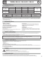 19
19
-
 20
20
-
 21
21
-
 22
22
-
 23
23
-
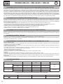 24
24
-
 25
25
-
 26
26
-
 27
27
-
 28
28
-
 29
29
-
 30
30
-
 31
31
-
 32
32
-
 33
33
-
 34
34
-
 35
35
-
 36
36
-
 37
37
-
 38
38
-
 39
39
-
 40
40
-
 41
41
-
 42
42
-
 43
43
-
 44
44
-
 45
45
-
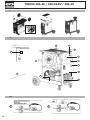 46
46
-
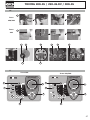 47
47
-
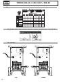 48
48
-
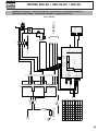 49
49
-
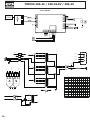 50
50
-
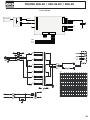 51
51
-
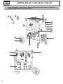 52
52
-
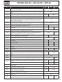 53
53
-
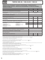 54
54
-
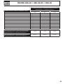 55
55
-
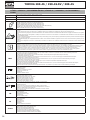 56
56
-
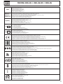 57
57
-
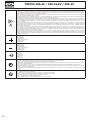 58
58
-
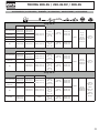 59
59
-
 60
60


GYS PROMIG 400 G DV Manuale utente
- Categoria
- Sistema di saldatura
- Tipo
- Manuale utente
- Questo manuale è adatto anche per
in altre lingue
- English: GYS PROMIG 400 G DV User manual
- français: GYS PROMIG 400 G DV Manuel utilisateur
- español: GYS PROMIG 400 G DV Manual de usuario
- Deutsch: GYS PROMIG 400 G DV Benutzerhandbuch
- русский: GYS PROMIG 400 G DV Руководство пользователя
- Nederlands: GYS PROMIG 400 G DV Handleiding
Documenti correlati
-
GYS TRIMIG 200-4S Manuale del proprietario
-
GYS TRIMIG 300-4S Scheda dati
-
-
GYS TRIMIG 200-4S Scheda dati
-
-
-
-
-
-
GYS M1 GYS AUTO Manuale del proprietario
