
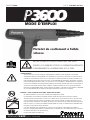
MODEL P3600 CAT. NO.52010/Deluxe Kit
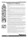
DO NOT OPERATE THE P3600 TOOL UNTIL YOU HAVE
READ THIS MANUAL AND RECEIVED THE PROPER
TRAINING ACCORDING TO ANSI STANDARD A10.3-1995.
WARNING
R2200
R2
2
0
0
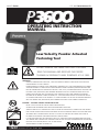
OPERATING INSTRUCTION
MANUAL
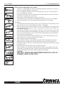
WARNING!
PRIOR TO OPERATING THE P3600 TOOL, STUDY THIS MANUAL CAREFULLY AND DEVELOP A THOROUGH
UNDERSTANDING OF THE CONTENTS.
PROPER TRAINING ACCORDING TO THE CURRENT ANSI STANDARD A 10.3, SAFETY REQUIREMENTS FOR POWDER
ACTUATED FASTENING SYSTEMS MUST BE COMPLETED AND A POWERS FASTENERS QUALIFIED OPERATOR CARD
MUST BE OBTAINED PRIOR TO OPERATION OF THE TOOL. STATE, LOCAL, OR OTHER REGULATIONS SHOULD ALSO BE
FOLLOWED. LAWS, REGULATIONS, AND STANDARDS REGARDING THE USE OF POWDER ACTUATED TOOLS MAY
PERIODICALLY BE REVISED. ANY SUCH REVISIONS MAY CHANGE THE SAFETY AND OPERATING PROCEDURES
DESCRIBED IN THIS MANUAL. POWERS FASTENERS, INC. IS NOT RESPONSIBLE FOR ANY SUCH REVISIONS WHICH
OCCUR AFTER PUBLICATION OF THIS MANUAL. IT IS THE RESPONSIBILITY OF THE USER TO MAINTAIN FAMILIARITY
WITH THE CURRENT LAWS, REGULATIONS, AND STANDARDS THAT APPLY TO THE POWDER ACTUATED TOOL.
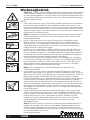
DANGER! - TO AVOID SERIOUS INJURY OR DEATH:
NEVER CLOSE TOOL WITH ANY PART OF HAND OVER MUZZLE END.
OPERATORS AND BYSTANDERS MUST WEAR EYE AND HEARING PROTECTION.
ALWAYS ASSUME TOOL IS LOADED. DO NOT PLACE A FINGER ON THE TRIGGER OF LOADED TOOL UNTIL MUZZLE
END IS AGAINST WORK SURFACE AND YOU ARE READY TO MAKE A FASTENING. NEVER PLACE YOUR HAND OVER
THE MUZZLE WITH A POWDER LOAD IN THE TOOL. IF THE TOOL ACCIDENTALLY DISCHARGES THE PISTON OR
FASTENER MAY PENETRATE YOUR HAND RESULTING IN SERIOUS INJURY.
IT IS VERY IMPORTANT THAT THE OPERATOR OF THIS TOOL COMPLETELY READS AND UNDERSTANDS THE ENTIRE
TOOL MANUAL AND COMPLETES THE OPERATOR’S EXAM ON THE LAST PAGE. THE WARRANTY WILL NOT BE VALID
UNTIL THE TEST IS RECEIVED, WITH A COPY OF YOUR RECEIPT,
AND REVIEWED BY POWERS FASTENERS, INC.
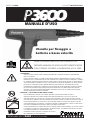
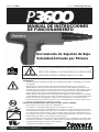
Low Velocity Powder Actuated
Fastening Tool
P3600 MANUAL CAT. NO. 52043 6/09
P36OO

MODEL P3600 CAT. NO.52010/Deluxe Kit
2 P3600
Introduction
Thank you for purchasing the Powers P3600 low velocity powder actuated tool. This tool will
provide you with excellent performance provided the steps for proper operation and
maintenance are followed. Powder actuated fastening systems can provide a cost effective
method of attaching fixtures for light duty, static load conditions. The systems provided by
Powers Fasteners consist of specially designed fasteners, installation tools, and powder loads
which are designed to function in combination to provide optimum performance. While powder
actuated tools can provide one of the fastest and economical means of fastening, they can also
be dangerous if they are not operated properly.
Prior to operating the P3600 tool, you must be properly trained in the operation and
maintenance of this tool and be issued a Powers Fasteners Qualified Operator Card. When using
the tool, you must have this card in your possession. As part of the training process, you should
read and understand the contents of this instruction manual especially the safety precautions.
Powder actuated tools may be operated only by properly trained operators as described in ANSI
Standard A 10.3, Safety Requirements for Powder Actuated Fastening Systems. For complete
tool operation details, contact your local Powers Fasteners Branch office or distributor
for training.
Remember, safety begins with you! It is your primary responsibility when operating this tool.
Failure to follow the proper operating, maintenance, and safety procedures can result in serious
injury or death to yourself or bystanders. In addition to the training provided, you should be
familiar with any local, state, and federal regulations. If you have any questions which are not
covered in this manual, contact your local Powers Fasteners Branch office or distributor.
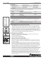
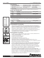
SIZE RANGE
Up to 3" (76mm) in length. 10mm Head Pins, 3/8"Threaded Studs,
3/8"Headed Drive Pins (.27 caliber )
TOOL DESCRIPTION
The P3600™ is a powerful, heavy-duty, low velocity, semi-automatic .27 caliber tool, which can
be used to install 10mm head .177 diameter shank drive pins, 3/8"-16 threaded studs, and 3/8"
headed drive pins. The P3600™ is designed for applications where more power is needed,
such as attaching 2x4 to hard aggregate or steel. The tool utilizes a red (5) or purple (6)
.27 caliber strip.
TECHNICAL DATA
TOOL BODY MAX PIN LENGTH TOOL LENGTH
Precision Cast Aluminum Up to 3" (76mm) Total Length 13-5/8" (346mm)
LOAD TYPE TOOL WEIGHT POWER LEVEL
.27 Caliber in a 10 Load Strip 5 lbs. (2.25 kg) Red (5), Purple (6)
PIN TYPE
10mm Head Pins, 3/8" Threaded Studs, 3/8" Headed Drive Pins
Warranty
All warranties of the products described herein, expressed or implied, including the warranties of
merchantability and fitness for particular purposes are specifically excluded, except for the
following: Powers Fasteners will repair or replace at its sole option any tool part, or fastener
which within five years after sale by Powers Fasteners or its distributors, is found by Powers
Fasteners to be defective in material or workmanship, normal wear and tear excluded.
This is the sole warranty of Powers Fasteners and the sole remedy available to distributor
or buyer.
NOTE — JUST AS NO ONE CAN MERELY READ A BOOK ABOUT DRIVING AN AUTOMOBILE AND THEN HOPE TO RUN IT SAFELY, NO ONE SHOULD
A
TTEMPT TO USE ANY POWDER TOOL WITHOUT ADEQUATE, COMPETENT, PERSONAL INSTRUCTION. AND, JUST AS NO AUTOMOBILE
INSTRUCTION BOOK OR INSTRUCTOR CAN FOREWARN A LEARNER AGAINST ALL CONTINGENCIES AND EMERGENCIES, NEITHER CAN POWERS
FASTENERS INSTRUCTORS OR PRINTED INFORMATION DETAIL ALL POSSIBLE CONDITIONS SURROUNDING THE USE OF POWERS TOOLS AND
P
RODUCTS. THE MANUFACTURER DISCLAIMS RESPONSIBILITY FOR INJURIES TO PERSONS OR PROPERTY WHICH MAY RESULT FROM DISREGARD
OF THESE OPERATING INSTRUCTIONS.

MODEL P3600 CAT. NO.52010/Deluxe Kit
3 P3600
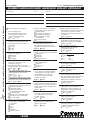
P3600 SELECTION GUIDE
CAT NO. DESCRIPTION STD CTN.
52010 P3600 Powder Tool (Deluxe Kit) 1
CAT NO. DESCRIPTION STD CTN.
52578
P3600 Piston
1
52579
P3600 Guide
1
52580
P3600 Base Plate
1
For fastening ceiling clips overhead, 6' (1.8m) and 8' (2.44m) di-electric pole tools are available.
CAT NO. DESCRIPTION STD CTN.
50065 6' (1.8m) Di-electric Pole Tool 1
50066 8' (2.44m) Di-electric Pole Tool 1
FASTENER FUNCTIONING
Prior to learning the safe operating procedures for this tool, it is important to understand how a
powder actuated fastener works. A powder actuated fastener is considered to be a direct drive or
forced entry type of fastener because it is driven directly into the base material. The driving action
causes tremendous forces to be applied to the fastener. Powers powder actuated fasteners are
specially designed and manufactured using an austempering process to withstand the forces
imposed during the driving operation. Only fasteners manufactured or supplied by Powers
Fasteners should be used in this tool.
FUNCTIONING IN CONCRETE
The performance of a powder actuated fastener when installed into concrete or masonry base
materials is based on the following factors:
1. Strength of the base material
2. Hardness and concentration of the aggregate
3. Shank diameter of the fastener
4. Depth of embedment into the base material
5. Fastener spacing and edge distance
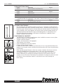
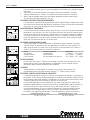
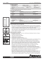
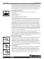
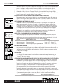
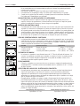
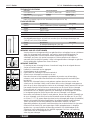
In addition to these factors, installation tool accessories such as a stop spall which reduces the
tendency of the concrete surface to spall during the driving action can increase the performance
of the fastener.
When a powder actuated fastener is driven into concrete, it displaces the volume of concrete
around the embedded area of the fastener shank. As this occurs, the concrete directly
surrounding the fastener is compressed and in turn presses back against the shank of the
fastener. Additionally, the driving action generates heat which causes particles within the
concrete to fuse to the shank of the fastener. This combination of compression and fusion holds
the fastener in the concrete base material. A similar action occurs when fastening into
block masonry.
Stop
Spall
Washer
Stop
Spall
Washer
1
2

MODEL P3600 CAT. NO.52010/Deluxe Kit
4 P3600
Point
Flattens
No
Indent
Surface
Shatters
Material
Cracks
Fastener Sinks in
with Average
Hammer Blow
1
2
3
Generally, the performance of the fastener in a given concrete strength will increase with
greater embedment depths in a certain range. Depending on the fastener style and base
material strength, embedment depths range from 5/8” (16mm) to 1-1/2” (38mm). For depths
greater than this range, there is the possibility of fastener bending or fishhooking which may
decrease expected load capacities and create a safety hazard.
During the driving action, some localized surface spalling of the concrete may occur. Normally,
this is a surface effect which does not effect the performance of the fastener. However, it may
pose an aesthetic problem for exposed applications where a fixture is not used. In cases such as
this, two methods can be used to improve the appearance of the fastening. A stop spall adapter
mounted on the powder actuated tool can help to reduce surface spalling. Another method used
is to drive the fastener through a steel washer to improve the appearance of the application.
FUNCTIONING IN STEEL
The load performance of a powder actuated fastener when installed into steel base materials
is based on the following factors:
1. Thickness of the steel
2. Tensile strength of the steel
3. Shank diameter of the fastener
4. Depth of point penetration through the steel
5. Fastener spacing and edge distance.
When a powder actuated fastener is driven into steel, it displaces the steel laterally 360˚ around
the shank of the fastener. Since steel is an elastic material, it presses back against the shank of
the fastener to hold it in place. As the diameter of the fastener shank is increased, the load
capacity obtained will generally increase provided the steel thickness is sufficient to accept the
fastener. To further increase fastener performance in steel, some fasteners have a knurled shank
which allows the steel to form a key lock into the grooves to provide higher capacities than those
obtained with a smooth shank. For optimum performance, the fastener point should completely
penetrate the steel. Normally, a minimum of 1/4” (6.35mm) is allowed for the point length. An
increase in performance can be expected until the fastener no longer completely penetrates
through the steel. At this point, the elastic properties of the steel cause a compression force to be
developed at an angle against the fastener point which reduces load capacity. In thicker steel
base materials, adequate load capacities may be obtained for applications in which the point of
the fastener does not fully penetrate the steel. Job site performance tests are recommended.
Fasteners should not be used in areas that have been welded or cut with a torch as these
procedures may have caused local hardening of the steel. Over driving of the fastener should be
avoided as the rebound created may reduce the load capacity or cause damage to the fastener.
When fastening into unsupported long steel members, it may be necessary to provide support in
the area of the fastening to prevent spring action which can cause inconsistent penetration and
a reduction in load capacity.
SUITABLE BASE MATERIAL
While powder actuated fasteners can be used successfully in concrete, certain masonry
materials, and A 36 steel, some materials are completely unsuitable. Fasteners should never
be fired into hard or brittle materials such as cast iron, tile, glass, or rock. These materials can
shatter easily resulting in a potential safety hazard. In addition, soft base materials such as
wallboard, plaster, or wood are not appropriate as the fastener could pass completely through
these materials. The user should never guess when fastening into any base material. Failure to
follow the recommended installation and safety guidelines can result in severe injury or death to
the tool operator and/or bystanders.
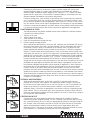
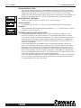
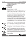
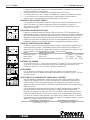
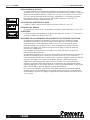
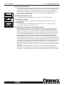
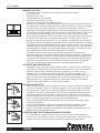
CENTER PUNCH TEST
A center punch test should always be performed to determine the suitability of the base
material for a powder actuated fastening. This test is relatively simple and can help to insure a
safe, successful fastening. Be sure to wear the appropriate eye protection when performing this
test. To begin, select the fastener to be used for the job. Then, place the point of the fastener
against the proposed base material. Strike the fastener with a single hammer blow, then
examine the point. If the point of the fastener is not blunted and the base material has a clear
point indentation, it is acceptable to proceed with the first test installation.

MODEL P3600 CAT. NO.52010/Deluxe Kit
5 P3600
Use of a powder actuated system is not recommended if the following occurs during the center
punch test:
1. The fastener point has been blunted. This indicates that the base material is too hard.
2. The base material cracks or shatters. This indicates that the base material is too brittle.
3. When using an average hammer blow, the fastener penetrates the base material easily.
This indicates that the base material is too soft.
FASTENER INSTALLATION REQUIREMENTS
It is important to understand the required minimum base material thickness requirements along
with the minimum spacing and edge distance requirements. Failure to follow these requirements
can result in an unsuccessful fastening and create a safety hazard.
BASE MATERIAL THICKNESS
Concrete base material should be at least three (3) times as thick as the fastener embedment
penetration. If the concrete is too thin, the compressive forces forming at the fasteners point
can cause the free face of the concrete to break away. This can create a dangerous condition
from flying concrete and/or the fastener and also results in a reduction of fastener holding
power. For applications in the face shell of concrete masonry block, select a fastener length
which will not exceed the thickness of the face shell.
FASTENER PENETRATION GUIDE
The following table lists typical embedment or penetration depths expected in the base
materials listed. The penetration will vary depending on the density of the material. This
table should be used as a guide since the consistency of these materials varies. When in
doubt, a job site performance test should be conducted.
DENSITY TYPICAL BASE MATERIAL PENETRATION
Soft Masonry Concrete block 1" (26mm) -1-1/4" (32mm)
Average concrete Poured concrete 3/4" (19mm) - 1" (26mm)
Dense concrete Pre-stressed/pre-cast concrete 5/8" (16mm) - 3/4" (19mm)
EDGE DISTANCE
Do not fasten closer than 3" (76mm) from the edge of concrete. If the concrete cracks, the
fastener may not hold. Closer edge distances for applications such as sill plates may be
permitted if specific fastener testing has been conducted.
SPACING
Setting fasteners too close together in concrete or masonry can cause cracking. The
recommended minimum distance between fasteners is 3" (76mm) center to center.
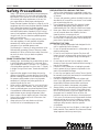
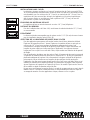
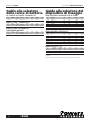
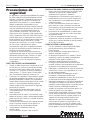
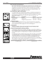
FASTENER LENGTH SELECTION IN CONCRETE
For permanent applications using pins in concrete, first determine the thickness of the fixture to
be fastened. To this, add the required embedment or penetration into the base material. This will
be the fastener shank length required. For applications in the face shell of masonry block, select
a fastener length which will not exceed the thickness of the face shell.
For removable applications with threaded studs, the shank length required is equal to the
embedment depth required. To determine the minimum threaded length, add the thickness of
the fixture and the nut / washer thickness. The nut and washer thickness is equal to the
nominal thread diameter. Do not over tighten threaded parts. Maximum tightening torque
values are listed in the table below. Use of a nut setter is recommended to reduce the
possibility of over tightening the fasteners. For critical applications, perform a job site test.
MAXIMUM TORQUE FOR 1/4" STUD MAXIMUM TORQUE FOR 3/8" STUD
2 ft.-lbs. or 2.7 Nm 4 ft.-lbs. or 5.4 Nm
3"
3"
Fixture
Embedment
Thread Length
Embedment
Penetration
3x
Penetration

MODEL P3600 CAT. NO.52010/Deluxe Kit
6 P3600
1
/8"
1
/2"
1
-1/2"
INSTALLATION IN STEEL
The following guidelines are based on the installation of a fastener in ASTM A 36 structural
steel with the point fully penetrating the steel member. Recommended steel material thickness
ranges from a minimum of 1/8" (3mm) to a maximum of 3/8"(10mm). For use in higher
strength structural steel, applications where the point does not penetrate the steel member, or a
thickness of steel greater than 3/8"(10mm), job site performance tests are recommended.
BASE MATERIAL THICKNESS
Steel base materials should be a minimum of 1/8" (3mm) in thickness.
EDGE DISTANCE
For installations in A 36 steel, 1/2" (13mm) is the recommended minimum edge distance.
SPACING
The recommended minimum distance between fastenings is 1-1/2" (38mm) center to center for
installations in ASTM A 36 steel.
FASTENER LENGTH SELECTION IN STEEL
For permanent applications when using pins in steel, first determine the thickness of the
fixture to be fastened. To this, add the thickness of the steel base material plus a minimum
of 1/4" (6mm) to allow for proper point penetration. This will be the minimum fastener shank
length required. Do not select a fastener length longer than that required for the application.
An excessively long shank can burnish or polish the hole created in the steel resulting in a
reduction in load capacity.
For removable applications with threaded studs, the shank length required is equal to the
thickness of the steel base material plus a minimum of 1/4" (6mm) to allow for proper point
penetration. This will be the minimum fastener shank length required. Do not select a shank
length longer than that required for the application. An excessively long shank can burnish or
polish the hole created in the steel resulting in a reduction in load capacity. To determine the
minimum threaded length, add the thickness of the fixture and the nut / washer thickness. The
nut and washer thickness is equal to the nominal thread diameter.
Do not over tighten threaded studs, the maximum tightening torque is listed in the table below.
Use of a nut setter is recommended to reduce the possibility of over tightening the fasteners.
For critical applications, perform a job site test.

MODEL P3600 CAT. NO.52010/Deluxe Kit
7 P3600
Powder Load
Selection Guide
.27 CALIBER 10 LOAD STRIPS
CAT. POWER LOAD STD. STD. MASTER WT./
NO. LEVEL COLOR SIZE BOX CTN. CTN. 100
50606 6 Purple .27 strip 100 1000 20000 .33
.27 CALIBER SAFETY STRIP
®
CAT. POWER LOAD STD. STD. MASTER WT./
NO. LEVEL COLOR SIZE BOX CTN. CTN. 100
5
0630 5 Red .27 strip 100 1000 20000 .33
.27 CALIBER SAFETY STRIP
®
MASTER PACK
CAT. POWER LOAD STD. STD. MASTER WT./
NO. LEVEL COLOR SIZE BOX CTN. CTN. 100
50632 5 Red .27 strip 1000 - 10000 .33
Fastener
Selection Guide
10MM HEAD DIAMETER DRIVE PINS
CAT. STD. STD. HEAD SHANK
NO. SHANK LENGTH BOX CTN. DIA. DIA.
50850 27mm - 1” 100 5000 10mm .177
50852 32mm -1-1/4” 100 5000 10mm .177
50854 42mm -1-5/8” 100 5000 10mm .177
50856 52mm -2” 100 5000 10mm .177
50858 62mm -2-1/2” 100 1000 10mm .177
50860 72mm -2-7/8” 100 1000 10mm .177
50862 82mm -3-1/4” 100 1000 10mm .177
3/8" HEAD DRIVE PINS
CAT. STD. STD. HEAD SHANK
NO. SHANK LENGTH BOX CTN. DIA. DIA.
5
0162 1" 100 1000 3/8" .171
5
0164 1-1/4" 100 1000 3/8" .171
5
0166 1-1/2" 100 1000 3/8" .171
5
0170 2" 100 1000 3/8" .171
5
0172 2-1/2" 100 1000 3/8" .171
5
0174 3" 100 1000 3/8" .171
5
0176 3-1/8" (w/step shank) 100 1000 3/8" .216/.188
3/8" -16 THREADED STUDS
CAT. THREAD SHANK STD. STD. HEAD SHANK
NO. LENGTH LENGTH BOX CTN. DIA. DIA.
50340† 1-1/4" 3/4" K 100 1000 3/8" .205
50342† 1-1/4" 1" 100 1000 3/8" .205
50344† 1-1/4" 1-1/4" 100 1000 3/8" .205
K=Knurled
† Factory Mutual Research Corp. approved for Pipe Hanger Components

MODEL P3600 CAT. NO.52010/Deluxe Kit
8 P3600
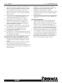
Safety Precautions
Safety is your primary responsibility when operating any
powder actuated tool. You must read and understand
the contents of this manual. You must be familiar with
all functional and safety requirements of the tool. It is
your responsibility to obtain proper training and a
Powers Fasteners operator card prior to using this tool in
compliance with the current American National Standard
A10.3 Safety Requirements for Powder Actuated
Fastening Systems and the Federal Occupational Safety
and Health Administration Standards (OSHA). Existing
state or local regulations should also be followed. When
using this tool, you must have the qualified operators
card in your possession.
Revocation of card - Failure to comply with any of the
rules and regulations for safe operation of powder
actuated tools shall be cause for the immediate
revocation of your qualified operator card.
The following is a summary of safety precautions to be
followed when operating a Powers Fasteners powder
actuated tool. Failure to follow these safety instructions
can result in serious injury or death to operators
or bystanders.
PRIOR TO OPERATING THE TOOL
1. Warning signs should always be posted within the area
in which a powder actuated tool is to be used. These
signs should be at least 8" (203mm) x 10" (254mm) in
size with boldface type that is not less than 1" (26mm)
in height. The sign should state "Powder Actuated Tool
In Use".
2. Approved safety goggles should always be worn by
operator or bystander, to protect their eyes from flying
particles. Hearing protection should always be worn by
the operator and bystanders when using a powder
actuated tool. Other personal safety protection as
required should also be used.
3. Never modify or fabricate parts for use in your Powers
tool. Use only Powers Fasteners, loads, and tool parts.
4. Hands or other body parts must never be placed in front
of muzzle/barrel. Accidental discharge can cause piston
and/or fastener to pass through the operator’s hand.
5. Never compress the tool against any part of the body.
Serious injury or death may result in the event of an
accidental discharge.
6. Always point tool in a safe direction at all times.
7. Use the tool for its intended purpose only.
PREPARATION FOR LOADING THE TOOL
1. Tools must be checked prior to operating to make sure
they are not fully or partially loaded with a powder load
or fastener.
2. To insure safe operation, perform the daily function test
described in this manual. Be sure the tool is not loaded
prior to performing this test.
3. Do not operate this tool unless all its parts are in place
and operating appropriately. Never attempt to use a
malfunctioning tool. Call 1-800-524-3244 for assistance.
4. Never guess about the suitability of a base material. If
you are uncertain about the suitability of a base
material, perform a center punch test.
5. Do not operate the tool until you learn and understand
the color code / numbering system used to identify the
power level of powder loads.
OPERATING THE TOOL
1. Only use fasteners and powder loads designed for this
tool as supplied by Powers Fasteners.
2. Do not use powder actuated tools in a flammable or an
explosive atmosphere.
3. Do not fire a tool without a fastener. The piston will
impact the work surface possibly causing serious injury
to the operator or bystanders along with damage to
the tool.
4. Do not load the tool until you are ready to make a
fastening. Check the power load level before inserting it
into the tool chamber.
5. Fastener must be loaded prior to loading the powder
load, to prevent injury to operator or bystander in the
event of an accidental discharge.
6. Do not close tool against work surface. The tool should
be manually closed, with hand away from muzzle/barrel
to prevent accidental discharge.
7. Hold the tool perpendicular to the work surface at all
times. Use a spall guard wherever possible. This will limit
the possibility of fastener ricochet which could cause
serious injury or death to the operator or bystanders.
8. Always perform a test fastening with the lightest load
level designed for use in the tool. If the lightest load
fails to set the fastener, try the next highest load until
the proper level is attained. Failure to follow this
procedure may cause the fastener to be overpowered.
If this occurs, the fastener may fully penetrate the base
material causing serious injury or death to someone.
Overpowering the fastener can also damage the tool,
creating a safety hazard to both the operator
or bystanders.
9. Do not fasten into cast iron, tile, glass, or other types of
brittle materials. These materials can shatter and create
sharp fragments which may cause injury.

MODEL P3600 CAT. NO.52010/Deluxe Kit
9 P3600
10. Do not fire tool within 3"(three inches) (76mm) of the
edge of a concrete base material or within 1/2"(one-
half inch) (13mm) of the edge of a steel base material.
11. Do not attempt to install a fastener closer than 3"
(three inches) (76mm) to another previously inserted
fastener in concrete or 1-1/2" (one and one-half inch)
(38mm) in steel.
12. Do not fasten into a concrete base material less than
3 times as thick as the fastener penetration or into
a steel base material thinner than 1/8”(3mm).
13. Never attempt to install a fastener in a cracked or
spalled area in concrete. Place fastener at least 3”
(three inches) (76mm) away from a spalled area to
prevent the possibility of the fastener bending and
striking an operator or bystander.
14. Do not attempt to install fasteners in areas that have
been welded or cut with a torch as these procedures
may have caused local hardening of the steel.
15. Do not fasten through a predrilled hole unless
proper guidance is provided.
16. If you decide not to make a fastening after the tool has
been loaded, you must always remove the powder load
first followed by the fastener.
17. Never attempt to override the safety features of this tool.
HANDLING THE TOOL AND POWDER LOADS
1. Never leave a loaded tool unattended. Once the tool
is loaded, make the fastening immediately or unload
the tool.
2. Always unload the tool before work breaks, changing
parts, cleaning or servicing, and when storing.
3. To prevent accidental discharge of loads, never carry the
powder loads in the same container as the fasteners or
other hard objects.
4. Always store the powder loads in the containers
provided or in an enclosure provided for them. Never
intermix the various power levels. Keep them
segregated in clearly identified containers.
5. Powder loads should never be used in firearms. They are
normally more powerful that the cartridges supplied
with the firearms.
6. Powder actuated tools and powder loads should always be
stored under lock and key. Tools must be unloaded when
not in use.
TOOL MALFUNCTION
1. In the event that a load fails to discharge after the
trigger is pulled, the tool must be kept depressed
against the work surface for a minimum of 30 (thirty)
seconds in case of a delayed load discharge. Then
carefully remove the entire load strip. and dispose of it
in a can of water or other nonflammable liquid. Never
attempt to force or pry a load out of a tool chamber.
2. Never discard unfired powder loads into a trash container.
3. Do not attempt to unload or disassemble a jammed,
stuck or broken tool as improper handling may cause it
to discharge and strike operator and/or bystander. A
jammed tool must be pointed in a safe direction at all
times. Tag the tool and lock it up. Call your Powers
Fasteners representative for proper assistance.

MODEL P3600 CAT. NO.52010/Deluxe Kit
10 P3600
R3500
R3500R3500
R3500R3500
R3500R3500
R3500R3500
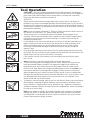
Tool Operation
CAUTION:
— Be sure to read and understand all of the safety precautions and training in
this manual before attempting to operate the tool. (Check to be sure the tool is not loaded, the
piston moves freely within the barrel, and no foreign objects or fasteners are in the barrel.)
Perform the daily function test before using the tool.
OPERATION
1. Always load the fastener before inserting powder load to prevent injury to the operator or
bystanders in the event of an accidental discharge. Place the fastener, point out, into the end of
the guide until the fluted tip fits inside. Do not use excessive force when inserting the fastener. If
excessive force is required, stop and determine why the fastener can not be inserted. Correct the
problem before proceeding.
Note: Do not use fasteners longer than 3" (76mm) as listed in the fastener selection section of
this manual. Pins longer than 2-1/2" (64mm) require pre-driving.
2. Always point the tool in a safe direction away from bystanders and the operator. In one
movement, slide the barrel forward then close it against the stop. The barrel should be pulled
fully forward to reset the piston for the next fastening. Loss of power may result from an
im properly positioned piston.
Do not attempt to close the tool by exerting force on the front of the barrel. Never place your
fingers or hands over muzzle end of the tool. The safe position for hands and fingers are as
shown in the diagram. Hands must never be placed in front of the tool muzzle or barrel.
In the event of an accidental discharge, the piston and/or fastener can pass through the
operator's hand.
3. Insert the powder load strip into the bottom of the tool handle starting with the lowest power
level, 5/Red. The strip should be inserted completely and should be flush with the bottom of the
handle. Always insert the strip from the bottom of the handle.
If this load does not fully set the fastener, try the next higher power level until the proper
level is found.
Note: Over driving or over powering a fastener can cause a safety hazard.
4. To make a fastening, place the tool against the work surface. Hold the tool firmly with two
hands and completely depress the barrel. Then squeeze the trigger. Always hold the tool
perpendicular to the work surface. Hold the tool firmly against the work surface to avoid
excessive recoil. Never depress the tool against anything except the work surface. Note: In the
event that the load does not discharge after the trigger is pulled, continue to hold the tool
depressed against the work surface for at least 30 (thirty) seconds in case of a delayed load
discharge. Then carefully remove the entire load strip and dispose of it in a can of water or other
non flammable liquid. Never attempt to force or pry a load out of a tool chamber. Do not
discard unfired loads into a trash container.
5. To prepare for the next fastening, point the tool in a safe direction. Always insert a new fastener
before loading or advancing the powder load strip. Insert the fastener as described in step 1.
Once the fastener is inserted, cycle the tool as described in step 2. Repeat this procedure for
subsequent fastenings. When the ten load strip has been completely fired, remove it by pulling it
from the top of the tool body.
Note: Do not attempt to unload or disassemble a jammed, stuck or broken tool as improper
handling may cause it to discharge and strike the operator and/or bystander. A jammed tool
must be pointed in a safe direction at all times. Tag the tool and lock it up. Call your Powers
Fasteners representative for proper assistance.

MODEL P3600 CAT. NO.52010/Deluxe Kit
11 P3600
Proper Maintenance and Cleaning
MAKE SURE THE TOOL IS NOT LOADED. BE SURE THE TOOL IS NOT HOT PRIOR TO
ATTEMPTING DISASSEMBLY OR CLEANING.
DAILY FUNCTION TEST
Check the functioning of the tool, without a powder load or fastener in the tool, by pushing down against the work
surface, pulling the trigger, and releasing the tool from the work surface. Function the unloaded tool several times and
insure that the breech parts and firing mechanism operate freely before fastening with the tool.
Your Powers Fasteners Authorized representative should be asked to assist the first time you disassemble and clean
your tool.
If you ever have any trouble reassembling the tool, or have any doubt about worn parts, call your Powers Fasteners
Authorized Powder Distributor.
CLEANING
AIl parts should be cleaned with detergent oil and the wire brushes supplied with your tool kit. Remove heavy dirt
build-up with the brush. After cleaning with oil, all parts should be wiped thoroughly dry. Excess oil will tend to collect
dirt and dust. Wear eye protection when cleaning the tool. The piston rod, barrel assembly, and receiver should all be
cleaned of excess dirt on a daily basis. Check the condition of the piston for damage from wear and deformation.
To maintain this tool in good working condition, it is necessary to disas semble and clean the entire tool if dirt is
evident in the breech face, or if the tool appears to lose power. All parts should be cleaned with oil and wire brushes.
Remove heavy dirt. All parts should be wiped thoroughly dry after cleaning with oil.
General tool mainte nance should be performed at six month intervals or more frequently as required by the frequency
of tool use.

MODEL P3600 CAT. NO.52010/Deluxe Kit
12 P3600
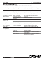
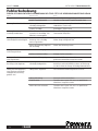
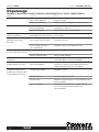
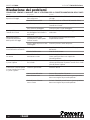
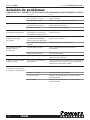
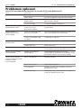
Troubleshooting
ALWAYS CHECK INSTRUCTION MANUAL FOR PROPER ASSEMBLY OF PARTS
PROBLEM POSSIBLE CAUSE SOLUTION
Fastener Overdriving Power level too high / Pin too short Use a lower powder load level number or a longer pin
Soft base material Check base material suitability section
Tool does not fire Tool not depressed completely See "Tool does not depress completely" section below
Firing pin damaged Replace damaged part(s)
Tool does not depress completely Damaged firing pin parts, ejector, Check the parts for damage or improper assembly
etc. Parts assembled improperly
Power reduction or inconsistent Barrel is not pulled fully Barrel must be pulled out completely to properly
fastener penetra tion forward when cycling tool. reset the piston
Worn or damaged piston Replace piston or piston ring
or piston ring
Load strip cannot be Improper loading Insert strip from the bottom of the tool handle
inserted into tool
Wrong caliber strip Use proper strip
Load strip will not advance Worn advance lever guide Replace advance lever guide.
This should be performed by qualified individuals
Load will not fire when Tool is not fully depressed Follow safety procedure for misfired load then
trigger is pulled attempt to fully depress tool before pulling trigger
Load will not fire when Load is already fired Cycle tool
tool is fully depressed
and trigger is pulled
Load misfire Follow safety procedure
Broken firing pin Replace firing pin nut. This should be performed by
qualified individuals
Broken or missing Replace firing pin nut. This firing pin nut should be
performed by qualified individuals

MODEL P3600 CAT. NO.52010/Deluxe Kit
13 P3600
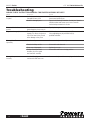
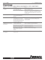
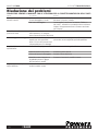
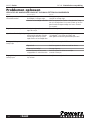
Troubleshooting
ALWAYS CHECK INSTRUCTION MANUAL FOR PROPER ASSEMBLY OF PARTS
PROBLEM POSSIBLE CAUSE SOLUTION
Tool cannot be opened Lack of proper cleaning Clean tool thoroughly
or cycled Damaged or bent piston Remove and replace piston
Broken or damaged parts Tag tool with warning "Defective - Do Not Use" place in
locked container and contact your Powers Fasteners
Authorized representative for service
Piston stuck in the forward Piston has been overdriven and is Tap the piston against a hard surface
position jammed against piston reset pin
Chipped or damaged piston Tool not held on work surface Machine piston as shown on page 14 (#7).
squarely. This allows the piston to Piston regrinding may be performed only by
slip off the head of the pin and qualified individuals
cause damage to the piston
Piston guide will not Bent shear clip Remove and replace shear clip
open easily
Excessive build-up of dirt Disassemble and clean tool
Piston stop is damaged Replace piston stop
Foreign material jammed Disassemble and remove foreign particles
between the piston guide
and steel liner assembly
Piston guide opens Annular ball spring or Remove and replace with a new spring and/or ball
too easily steel annular ball have worn

MODEL P3600 CAT. NO.52010/Deluxe Kit
14 P3600
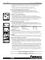
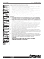
REPLACING OR REPAIRING THE PISTON
The piston is an expendable part and must be replaced periodically. Typical signs of a worn out
piston are: breaking, bending or mushrooming.
Prior to servicing the tool make sure there is no powder load in the tool. Use caution and do
not lose or damage any tool parts.
1. Using a pin, lift the end of the annular ball spring and rotate toward the top of the tool body.
Pull the piston stop back and out of the tool.
2. Slide the piston guide and baseplate assembly out of the tool.
3. Using a fastener, pry the shear clip off the baseplate. Replace the shear clip if it is damaged.
4. Remove the baseplate from the piston guide, then pull the piston out of the guide.
REASSEMBLY:
5. Tilt the baseplate and slide the fastener guide out. Press the guide out of the baseplate using a
piston if it does not slide out freely. Replace the guide if it is damaged.
6. Clean the piston using a wire brush. Inspect it for worn or damaged piston ring, chipped end, or
bending. Apply lubricant to the piston shank to minimize piston sticking from an overdrive con -
dition. Wipe the piston dry.
7. If a piston tip is damaged, it can be shortened a maximum of 0.20 inches (5mm). The tip of the
piston should be ground flat and at 90 degrees to the shank of the piston. The cham fer of the
piston must also be reground as shown. Piston grinding should be performed by qualified per -
sonnel using the proper equipment.
8. Press the piston into the end of the piston guide. Be sure to push it all the way back into the
guide. Ensure piston is positioned correctly in piston guide.
9. Insert the fastener guide into the baseplate.
10. Align the groove in both the piston guide and baseplate. Slide the baseplate (with fastener
guide) onto the piston guide. Press the shear clip into place. Insert the piston guide and
baseplate assembly into the liner in the tool body. Be sure to align the groove with the opening
for the piston stop.
11. Replace the piston stop and rotate the annular spring into place.
Upon reassembly of the tool perform the following test. Depress the tool against a flat, hard
surface and pull the trigger. The barrel assembly should slide smoothly inside the tool housing
assembly. The firing pin should release after the trigger has been pulled.
CAUTION:
THIS TEST SHOULD BE PERFORMED WITHOUT A PIN OR
POWDER LOAD IN THE TOOL.
1
2
3
4
6
5
10°
0.120"
7
8
9
10
11

MODEL P3600 CAT. NO.52010/Deluxe Kit
15 P3600
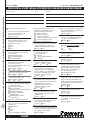
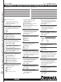
QUALIFIED TOOL OPERATOR EXAMINATION
■
■
✓ Check the correct answer.
1 It is necessary to read the Operator’s Manual
prior to operating a Powers Fasteners low
velocity tool.
■
■
True
■
■
False
2 When fastening into concrete, the base
material should be greater than the shank
penetration by at least:
■
■
1 time
■
■
2 times
■
■
3 times
3 When operating a powder actuated tool, your
hand should never be placed:
■
■
around the tool body
■
■
in front of the tool muzzle
■
■
over the tool handle
4 To determine the suitability of a base
material, use the fastener as a center punch.
• If the fastener is blunted, do not fasten; the
material is too:
■
■
soft
■
■
hard
■
■
brittle
• If the fastener penetrates easily, do not
fasten; the material is too:
■
■
soft
■
■
hard
■
■
brittle
• If the material cracks or shatters, do not
fasten; the material is too:
■
■
soft
■
■
hard
■
■
brittle
5 Unsafe applications for powder actuated tools
may be caused by which of the following?
■
■
a soft base material
■
■
improper powder load
■
■
fastening too close to
an unsupported edge
■
■
a malfunctioning tool
■
■
fastening into a spalled area
■
■
fastening through a
pre-existing hole
■
■
all of the above
6 Which one of the following building materials
is not suitable as a receiving material (base
material) for powder actuated fasteners?
■
■
sheet rock
■
■
wood
■
■
fiberglass
■
■
sheet metal
■
■
all of the above
7 When considering the safety of a particular
application, the operator must think about:
■
■
the base material
■
■
the powder load power level
■
■
the operator’s safety
■
■
the safety of bystanders
and fellow workers
■
■
all of the above
8 The proper loading procedure is: insert fastener
first, powder load second. The fastener should
always be placed in the tool prior to the load.
■
■
True
■
■
False
9 Which one of the following materials is
usually suitable for powder actuated
fastenings?
■
■
poured concrete
■
■
hollow tile
■
■
surface hardened steel
■
■
glazed brick
10 In concrete, a fastener should be
driven no closer to an unsupported
edge than:
■
■
1/2"(13mm)
■
■
1-1/2"(38mm)
■
■
3"(76mm)
11 Fishhooking is a condition which
can occur when a powder actuated
fastener strikes a piece of hard aggregate or
very hard concrete, bends and comes out of the
work surface. A fishhook can cause a serious
injury or death.
■
■
True
■
■
False
12 Placing a hand over the muzzle bushing of a
loaded tool can result in serious injury from
piston overdrive or an escaping fastener if the
tool is discharged accidentally.
■
■
True
■
■
False
13 Piston overdrive is caused by overpowering of
the tool or by discharging the tool against a
soft surface.
■
■
True
■
■
False
14 Malfunctioning tools cannot be used and
must be removed from service immediately.
■
■
True
■
■
False
15 After conducting a Center Punch Test,
the best way to check the base material
is to set several fasteners using the least
powerful load.
■
■
True
■
■
False
16 Safety goggles and hearing protection should
not be worn by the operator and any
necessary bystanders when using the tool.
■
■
True
■
■
False
17 A powder actuated tool cannot be safely used
in an explosive or flammable atmosphere.
■
■
True
■
■
False
18 List the proper powder load level number
(1-6) next to each
color listed.
Red ___ Brown ___
Green ___ Yellow ___
Gray ___ Purple ___
19 The weakest power level should
be used when making the first fastening.
■
■
True
■
■
False
20 You can fasten into welded areas
of steel.
■
■
True
■
■
False
P3600
• The proper procedure if a powder load fails to
ignite is to hold the tool against the work
surface and wait 30 seconds, then proceed
exactly as directed in the Operator’s Manual.
■
■
True
■
■
False
• Powers Fasteners powder loads for the P3600
are .22 caliber, "A" tapered, neck down, rim
fire, short crimped cartridges. No other
powder load may be used in this tool.
■
■
True
■
■
False
• Operators should never compress the P3600
or any other powder actuated tool against
any part of their body.
■
■
True
■
■
False
• If a piston buffer for the P3600 becomes
deformed, simply remove it, and use the tool
without the buffer?
■
■
True
■
■
False
OPERATOR’S NAME DATE
HOME ADDRESS
A
GE DATE OF BIRTH
COMPANY NAME
COMPANY ADDRESS
C
OMPANY PHONE
SIGNATURE DATE
TRIM ALONG DOTTED LINE, PLACE IN ENVELOPE, ADDRESS AS SHOWN AND AFFIX POSTAGE

MODEL P3600 CAT. NO.52010/Deluxe Kit
16 P3600
LICENSE AND WARRANTY ACTIVATION
T
HE P3600 TOOL IS WARRANTED FOR 5 YEARS FROM DATE OF PURCHASE.
I certify that I have read and understand the P3600 Tool Operating Instruction Manual and have taken the Operator’s exam. I understand
t
he importance of following all safety procedures and that failure to read, comprehend, and follow the detailed rules and warnings
regarding the safe operation of powder actuated tools can result in serious injury or death to the tool operator or bystanders. I agree to
conform to all the rules and regulations regarding the use of powder actuated tools. (Please print clearly)
THE SERIAL NUMBER ON MY TOOL IS:
PLEASE SEND MY TOOL LICENSE TO:
NAME
ADDRESS
CITY STATE ZIP PHONE
M A I L T O :
Tool License Coordinator
Powers Fasteners, Inc.
2 Powers Lane
Brewster, NY 10509
TRIM ALONG DOTTED LINE, PLACE IN ENVELOPE, ADDRESS AS SHOWN AND AFFIX POSTAGE

MODELL P3600 KATALOGNR. 52010/Deluxe Kit
ARBEITEN SIE ERST DANN MIT DEM P3600, NACHDEM SIE DIESE
ANLEITUNG GELESEN UND DIE ENTSPRECHENDE AUSBILDUNG
NACH ANSI-NORM A10.3-1995 ERHALTEN HABEN.
WARNUNG
R2200
R2
2
0
0
BEDIENUNGSANLEITUNG
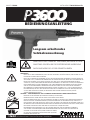
WARNUNG!
BEVOR SIE MIT DEM P3600 ARBEITEN, LESEN SIE DIESE ANLEITUNG SORGFÄLTIG DURCH, UND MACHEN SIE SICH
EINGEHEND MIT DEREN INHALT VERTRAUT.
BEVOR SIE DAS WERKZEUG VERWENDEN, MÜSSEN SIE EINE ANGEMESSENE AUSBILDUNG NACH DER AKTUELLEN
ANSI-NORM A 10.3, SICHERHEITSANFORDERUNGEN FÜR SETZBOLZENSYSTEME, ABGESCHLOSSEN HABEN UND IM
BESITZ EINES AUSWEISES VON POWERS FASTENERS SEIN, DER SIE ALS QUALIFIZIERTEN BEDIENER AUSWEIST.
STAATLICHE, LOKALE ODER ANDERE BESTIMMUNGEN SIND EBENFALLS ZU BEACHTEN. GESETZE, BESTIMMUNGEN
UND NORMEN BEZÜGLICH DER VERWENDUNG VON SETZBOLZENWERKZEUGEN WERDEN UNTER UMSTÄNDEN
VON ZEIT ZU ZEIT ÜBERARBEITET. ÄNDERUNGEN DIESER ART KÖNNEN SICH AUF DIE IN DIESEM HANDBUCH
BESCHRIEBENEN SICHERHEITSVERFAHREN AUSWIRKEN. POWERS FASTENERS, INC. IST NICHT VERANTWORTLICH
FÜR ÄNDERUNGEN, DIE NACH DER VERÖFFENTLICHUNG DIESES HANDBUCHS ERFOLGEN. DER BENUTZER MUSS
SICH MIT DEN AKTUELLEN GESETZEN, BESTIMMUNGEN UND NORMEN VERTRAUT MACHEN, DIE FÜR
SETZBOLZENWERKZEUGE GELTEN.
GEFAHR! – ZUR VERMEIDUNG VON SCHWEREN VERLETZUNGEN ODER TODESFÄLLEN:
BEDECKEN SIE DIE MÜNDUNG DES WERKZEUGS NIEMALS MIT DER HAND.
BEDIENER UND ZUSCHAUER MÜSSEN AUGEN- UND GEHÖRSCHUTZ TRAGEN.
GEHEN SIE IMMER DAVON AUS, DASS DAS WERKZEUG GELADEN IST. SETZEN SIE ERST DANN EINEN FINGER AUF
DEN AUSLÖSER DES GELADENEN WERKZEUGS, WENN DIE MÜNDUNG AUF DIE ARBEITSFLÄCHE GERICHTET IST
UND SIE BEREIT SIND, EINEN BOLZEN ZU SETZEN. LEGEN SIE NIEMALS DIE HAND AUF DIE MÜNDUNG, WENN SICH
IM WERKZEUG EINE PULVERLADUNG BEFINDET. WENN DAS WERKZEUG VERSEHENTLICH AUSGELÖST WIRD, KANN
DER KOLBEN ODER BOLZEN IHRE HAND DURCHSCHLAGEN UND SCHWER VERLETZEN.
DER BEDIENER DIESES WERKZEUGS MUSS DIE GESAMTE ANLEITUNG FÜR DAS WERKZEUG UNBEDINGT
VOLLSTÄNDIG LESEN UND KENNEN UND DIE BEDIENERPRÜFUNG AUF DER LETZTEN SEITE ABLEGEN. DIE
GARANTIE IST ERST DANN GÜLTIG, WENN POWERS FASTENERS,
INC. DEN TEST ZUSAMMEN MIT EINER KOPIE IHRER QUITTUNG
ERHALTEN UND GEPRÜFT HAT.
Langsam arbeitendes
Setzbolzenwerkzeug
P3600 BEDIENUNGSANLEITUNG KATALOGNR. 52043 6/09
P36OO
TRIM ALONG DOTTED LINE, PLACE IN ENVELOPE, ADDRESS AS SHOWN AND AFFIX POSTAGE

MODELL P3600 KATALOGNR. 52010/Deluxe Kit
18 P3600
Garantie
Alle ausdrücklichen oder inkludenten Garantien für die hier beschriebenen Produkte einschließlich
der Garantien der Marktfähigkeit und Eignung für bestimmte Zwecke sind bis auf die folgende
Garantie ausgeschlossen: Werkzeugteile oder Bolzen, die innerhalb von fünf Jahren nach dem
Verkauf durch Powers Fasteners oder seine Händler Material- oder Herstellungsfehler aufweisen,
werden von Powers Fasteners nach eigenem Ermessen repariert oder ersetzt; normale Abnutzung
und Verschleiß sind dabei ausgeschlossen.
Dies ist die einzige Garantie von Powers Fasteners und das einzige Rechtsmittel, das Händlern
oder Käufern zur Verfügung steht.
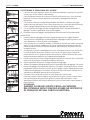
HINWEIS — NIEMAND KANN NACH DER LEKTÜRE EINES BUCHES ÜBER DAS AUTOFAHREN HOFFEN, ES SICHER ZU STEUERN. EBENSO
SOLLTE NIEMAND VERSUCHEN, EIN SETZBOLZENWERKZEUG OHNE ANGEMESSENE, KOMPETENTE, PERSÖNLICHE ANLEITUNG ZU VERWENDEN.
U
ND KEINE BEDIENUNGSANLEITUNG FÜR EIN AUTO UND KEIN FAHRLEHRER KANN DEN LERNENDEN IM VORAUS VOR ALLEN EREIGNISSEN
UND NOTSITUATIONEN WARNEN. EBENSO KÖNNEN AUCH DIE AUSBILDER ODER PUBLIKATIONEN VON POWERS FASTENERS NICHT ALLE
MÖGLICHEN ANWENDUNGSFÄLLE FÜR POWERS-WERKZEUGE UND -PRODUKTE NENNEN. DER HERSTELLER ÜBERNIMMT KEINE
V
ERANTWORTUNG FÜR PERSONEN- ODER EIGENTUMSSCHÄDEN, DIE DURCH DIE NICHTBEACHTUNG DIESER BEDIENUNGSANLEITUNG
ENTSTEHEN KÖNNEN.
Einführung
Vielen Dank für den Kauf des langsamen Powers-Setzbolzenwerkzeugs P3600. Dieses Werkzeug
bietet eine ausgezeichnete Leistung, falls Bedienung und Wartung ordnungsgemäß ausgeführt
werden. Setzbolzensysteme können ein kostengünstiges Mittel zum Anbringen von Vorrichtungen
für leichte und statische Belastungen sein. Die Systeme von Powers Fasteners bestehen aus
speziell konzipierten und aufeinander abgestimmten Befestigungsmitteln, Installationswerkzeugen
und Pulverladungen, die eine optimale Leistung bieten. Setzbolzenwerkzeuge zählen zu den
schnellsten und wirtschaftlichsten Befestigungswerkzeugen; sie können jedoch auch gefährlich
sein, wenn sie nicht ordnungsgemäß bedient werden.
Bevor Sie mit dem Werkzeug P3600 arbeiten, müssen Sie in Bedienung und Wartung dieses
Werkzeugs angemessen ausgebildet sein und von Powers Fasteners einen Nachweis als
qualifizierter Bediener erhalten haben. Wenn Sie mit dem Werkzeug arbeiten, müssen Sie diesen
Ausweis mit sich führen. Im Rahmen der Schulung müssen Sie diese Bedienungsanleitung,
insbesondere die Sicherheitshinweise lesen und verstehen.
Setzbolzenwerkzeuge dürfen nur von ordnungsgemäß ausgebildeten Bedienern verwendet
werden entsprechend der Beschreibung in der ANSI-Norm A 10.3, Sicherheitsanforderungen für
Setzbolzensysteme. Eine umfassende Bedienungsanleitung und Einweisung erhalten Sie von der
lokalen Niederlassung oder dem lokalen Vertrieb von Powers Fasteners.
Denken Sie daran, Sicherheit beginnt bei Ihnen! Beim Arbeiten mit diesem Werkzeug ist dies Ihre
Hauptaufgabe. Wenn Sie Bedienungs-, Wartungs- und Sicherheitsvorschriften nicht
ordnungsgemäß beachten, können Sie selbst oder Unbeteiligte schwer verletzt oder getötet
werden. Sie müssen nicht nur die Ausbildung durchführen, sondern sich auch mit allen lokalen
und staatlichen Vorschriften vertraut machen. Wenn Fragen auftauchen, die in diesem Handbuch
nicht behandelt werden, wenden Sie sich an die lokale Zweigniederlassung oder den lokalen
Vertrieb von Powers Fasteners.
GRÖSSENBEREICH
Länge maximal 76 mm. Stifte mit 10-mm-Kopf, 10-mm-Gewindestifte, Treibstifte mit 10-mm-Kopf
(Kaliber 0,27)
WERKZEUGBESCHREIBUNG
Das P3600™ ist ein leistungsstarkes, langsam arbeitendes, halbautomatisches
Hochleistungswerkzeug vom Kaliber 0,27, das für die Anbringung von Treibstiften mit 10-mm-
Kopf und einem Schaftdurchmesser von 0,177 Zoll, 10-mm-16-Gewindebolzen und Treibstiften
mit 10-mm-Kopf verwendet werden kann. Das P3600™ ist für Anwendungsfälle vorgesehen, in
denen eine höhere Leistung benötigt wird, etwa für die Anbringung in harten Aggregatstoffen
oder Stahl. Im Werkzeug wird ein roter (5) oder violetter (6) Streifen des Kalibers 0,27 verwendet.

MODELL P3600 KATALOGNR. 52010/Deluxe Kit
19 P3600
T
ECHNISCHE DATEN
W
ERKZEUGKÖRPER MAXIMALE STIFTLÄNGE WERKZEUGLÄNGE
P
räzisionsaluminiumguss Gesamtlänge maximal 76 mm 346 mm
LADUNGSTYP WERKZEUGGEWICHT STÄRKE DER LADUNGEN
Kaliber 0,27 in einem Streifen mit 10 Ladungen 2,25 kg rot (5), violett (6)
S
TIFTTYP
S
tifte mit 10-mm-Kopf, 10-mm-Gewindestifte, Treibstifte mit 10-mm-Kopf
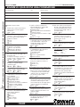
P3600-AUSWAHLANLEITUNG
K
ATALOGNR. BESCHREIBUNG STANDARDPACKUNG
52010 Setzbolzenwerkzeug P3600 (Deluxe-Ausstattung)1
K
ATALOGNR. BESCHREIBUNG STANDARDPACKUNG
52578
P3600-Kolben
1
52579
P3600-Anleitung
1
52580
P3600-Auflagerplatte
1
Zur Befestigung von Deckenhalterungen über Kopf stehen 1,8 und 2,44 m lange dielektrische
Stangenwerkzeuge zur Verfügung.
KATALOGNR. BESCHREIBUNG STANDARDPACKUNG
50065 dielektrisches Werkzeug mit 1,8-m-Stange 1
50066 dielektrisches Werkzeug mit 2,44-m-Stange 1
FUNKTIONSWEISE VON SETZBOLZEN
Bevor Sie die sichere Bedienung dieses Werkzeugs erlernen, müssen Sie wissen, wie Setzbolzen
funktionieren. Ein Setzbolzen ist ein direkt oder unter Druck eingetriebenes Befestigungsmittel, da
er direkt in das Tragschichtmaterial getrieben wird. Beim Eintreiben wirken gewaltige Kräfte auf
den Bolzen. Setzbolzen von Powers sind speziell konstruiert und werden in einem
Zwischenstufenvergütungsverfahren gefertigt, damit sie den während des Eintreibens ausgeübten
Kräften widerstehen. In diesem Werkzeug dürfen nur Bolzen verwendet werden, die von Powers
Fasteners hergestellt oder geliefert werden.
FUNKTIONSWEISE IN BETON
Die Leistung eines in einer Tragschicht aus Beton oder Mauerwerk befestigten Setzbolzens hängt von
den folgenden Faktoren ab:
1. Festigkeit des Tragschichtmaterials
2. Härte und Konzentration des Aggregats
3. Schaftdurchmesser des Bolzens
4. Einbindungstiefe im Tragschichtmaterial
5. Bolzenabstand und Abstand von der Materialkante
Zusätzlich lässt sich die Leistung des Bolzens durch Werkzeugzubehör wie eine Abplatzsicherung
erhöhen. Diese reduziert das Abplatzen der Betonoberfläche beim Eintreiben des Bolzens.
Wenn ein Setzbolzen in Beton getrieben wird, verdrängt er den Beton um den eingebundenen
Bereich des Bolzenschafts. Dabei wird der Beton direkt um den Bolzen komprimiert, so dass er
seinerseits wiederum gegen den Schaft des Bolzens drückt. Zusätzlich entsteht beim Eintreiben
Wärme, wodurch Betonpartikel mit dem Schaft des Bolzens verschmelzen. Durch diese
Kombination von Pressung und Schmelzung wird der Bolzen in der Tragschicht aus Beton
festgehalten. Ähnliches geschieht, wenn der Bolzen in Mauerwerk befestigt wird.
Grundsätzlich nimmt die Leistung des Bolzens bei einer bestimmten Betonfestigkeit je nach
Einbindungstiefe in einem bestimmten Bereich zu. Je nach Bauart des Bolzens und Festigkeit der
Tragschicht reicht die Einbindungstiefe von 16 mm bis 38 mm. Bei einer größeren Tiefe kann sich
der Bolzen verbiegen und die Form eines Angelhakens annehmen, so dass die erwartete
Belastungsfähigkeit eventuell abnimmt; dies kann ein Sicherheitsrisiko darstellen.
Während des Eintreibens kann der Beton stellenweise abplatzen. Normalerweise handelt es sich
hierbei um einen Oberflächeneffekt, der keine Auswirkungen auf die Leistung des Bolzens hat.
Jedoch kann dies bei sichtbaren Anwendungen, in denen keine Montagevorrichtung verwendet
wird, ein ästhetisches Problem darstellen. In solchen Fällen kann man das Erscheinungsbild der
Stop
Spall
Washer
Stop
Spall
Washer
1
2

MODELL P3600 KATALOGNR. 52010/Deluxe Kit
20 P3600
Point
Flattens
No
Indent
Surface
Shatters
Material
Cracks
Fastener Sinks in
with Average
Hammer Blow
1
2
3
Befestigung auf zweierlei Weise verbessern. Das Abplatzen der Oberfläche lässt sich durch eine
auf dem Setzbolzenwerkzeug montierte Abplatzsicherung verringern. Eine weitere Möglichkeit
besteht darin, den Bolzen durch eine Unterlegscheibe aus Stahl zu treiben, um das
Erscheinungsbild der Befestigung zu verbessern.
FUNKTIONSWEISE IN STAHL
Die Belastungsleistung eines in einer Tragschicht aus Stahl befestigten Setzbolzens hängt von den
folgenden Faktoren ab:
1. Stärke des Stahls
2. Zugfestigkeit des Stahls
3. Schaftdurchmesser des Bolzens
4. Eindringungstiefe der Bolzenspitze durch den Stahl
5. Bolzenabstand und Abstand von der Materialkante
Wenn ein Setzbolzen in Stahl getrieben wird, verdrängt er den Stahl seitlich rund um den
Bolzenschaft. Da Stahl ein elastisches Material ist, drückt er gegen den Schaft des Bolzens und
hält diesen fest. Mit zunehmendem Schaftdurchmesser des Bolzens nimmt die erreichte Nutzlast
im Allgemeinen zu, falls die Stahlstärke zur Aufnahme des Bolzens ausreicht. Um die Leistung
eines Bolzens in Stahl weiter zu erhöhen, besitzen einige Bolzen einen gerändelten Schaft, so
dass der Stahl sich in den Rillen verkeilt. Bolzen dieser Art können stärker belastet werden als
Bolzen mit glattem Schaft. Um eine optimale Leistung zu erzielen sollte die Bolzenspitze den
Stahl vollständig durchdringen. Normalerweise ist eine Mindestspitzenlänge von 6,35 mm
zulässig. Eine höhere Leistung ist zu erwarten, bis der Bolzen den Stahl nicht mehr vollständig
durchdringt. An diesem Punkt entwickelt sich aufgrund der elastischen Eigenschaften des Stahls
eine Komprimierungskraft, die in einem Winkel gegen die Bolzenspitze wirkt, so dass sich die
Nutzlast reduziert. In stärkeren Tragschichten aus Stahl lassen sich hinreichende Nutzlasten für
Anwendungsfälle erzielen, in denen die Bolzenspitze den Stahl nicht mehr vollständig
durchdringt. Leistungstests vor Ort sind empfehlenswert.
In Bereichen, die geschweißt oder mit einem Schweißbrenner geschnitten wurden, sollten keine
Bolzen gesetzt werden, da der Stahl durch diese Bearbeitung lokal verhärtet sein kann. Ein zu
starkes Eintreiben des Bolzen ist zu vermeiden, da sich durch den dabei erzeugten Rückschlag die
Nutzlast verringern oder der Bolzen beschädigt werden kann. Wenn Bolzen in freitragenden
langen Stahlgliedern befestigt werden, muss der entsprechende Bereich eventuell gestützt
werden, damit der Stahl nicht federt, denn dies kann zu einer ungleichmäßigen Durchdringung
und damit zu einer Reduzierung der Nutzlast führen.
GEEIGNETES TRAGSCHICHTMATERIAL
Während Setzbolzen erfolgreich in Beton, bestimmte Mauerwerksmaterialien und A 36-Stahl
getrieben werden können, sind manche Materialien vollständig ungeeignet. Bolzen sollten nie in
hartes oder sprödes Material wie Gusseisen, Ziegel, Glas oder Fels geschossen werden. Diese
Materialien können ohne weiteres splittern, was zu einem potenziellen Sicherheitsrisiko führt.
Weiche Tragschichtmaterialien wie Leichtbauplatten, Gips oder Holz eignen sich nicht, da der
Bolzen diese Materialien vollständig durchschlagen kann. Der Anwender sollte sich bei
Befestigungen in Tragschichtmaterialien nie auf Vermutungen verlassen. Wenn Sie die
empfohlenen Installations- und Sicherheitsrichtlinien nicht beachten, können der Bediener oder
Unbeteiligte schwer verletzt oder getötet werden.
KÖRNUNGSTEST
Sie sollten stets einen Körnungstest durchführen, um die Eignung des Tragschichtmaterials für
Setzbolzen zu ermitteln. Dieser Test ist relativ einfach und ist gewährleistet eine sichere,
erfolgreiche Befestigung. Tragen Sie während dieses Tests den entsprechenden Augenschutz.
Wählen Sie zunächst den für Zweck zu verwendenden Bolzen aus. Setzen Sie dann die
Bolzenspitze auf das vorgesehene Tragschichtmaterial. Schlagen Sie einmal mit dem Hammer auf
den Bolzen, und untersuchen Sie dann die Spitze. Wenn die Bolzenspitze nicht stumpf geworden
ist und im Tragschichtmaterial eine deutliche Einkerbung zu sehen ist, können Sie die erste
Testinstallation vornehmen.
Wenn während des Körnungstests Folgendes geschieht, ist von der Verwendung eines
Setzbolzensystems abzusehen:
La pagina si sta caricando...
La pagina si sta caricando...
La pagina si sta caricando...
La pagina si sta caricando...
La pagina si sta caricando...
La pagina si sta caricando...
La pagina si sta caricando...
La pagina si sta caricando...
La pagina si sta caricando...
La pagina si sta caricando...
La pagina si sta caricando...
La pagina si sta caricando...
La pagina si sta caricando...
La pagina si sta caricando...
La pagina si sta caricando...
La pagina si sta caricando...
La pagina si sta caricando...
La pagina si sta caricando...
La pagina si sta caricando...
La pagina si sta caricando...
La pagina si sta caricando...
La pagina si sta caricando...
La pagina si sta caricando...
La pagina si sta caricando...
La pagina si sta caricando...
La pagina si sta caricando...
La pagina si sta caricando...
La pagina si sta caricando...
La pagina si sta caricando...
La pagina si sta caricando...
La pagina si sta caricando...
La pagina si sta caricando...
La pagina si sta caricando...
La pagina si sta caricando...
La pagina si sta caricando...
La pagina si sta caricando...
La pagina si sta caricando...
La pagina si sta caricando...
La pagina si sta caricando...
La pagina si sta caricando...
La pagina si sta caricando...
La pagina si sta caricando...
La pagina si sta caricando...
La pagina si sta caricando...
La pagina si sta caricando...
La pagina si sta caricando...
La pagina si sta caricando...
La pagina si sta caricando...
La pagina si sta caricando...
La pagina si sta caricando...
La pagina si sta caricando...
La pagina si sta caricando...
La pagina si sta caricando...
La pagina si sta caricando...
La pagina si sta caricando...
La pagina si sta caricando...
La pagina si sta caricando...
La pagina si sta caricando...
La pagina si sta caricando...
La pagina si sta caricando...
La pagina si sta caricando...
La pagina si sta caricando...
La pagina si sta caricando...
La pagina si sta caricando...
La pagina si sta caricando...
La pagina si sta caricando...
La pagina si sta caricando...
La pagina si sta caricando...
La pagina si sta caricando...
La pagina si sta caricando...
La pagina si sta caricando...
La pagina si sta caricando...
La pagina si sta caricando...
La pagina si sta caricando...
La pagina si sta caricando...
La pagina si sta caricando...
-
 1
1
-
 2
2
-
 3
3
-
 4
4
-
 5
5
-
 6
6
-
 7
7
-
 8
8
-
 9
9
-
 10
10
-
 11
11
-
 12
12
-
 13
13
-
 14
14
-
 15
15
-
 16
16
-
 17
17
-
 18
18
-
 19
19
-
 20
20
-
 21
21
-
 22
22
-
 23
23
-
 24
24
-
 25
25
-
 26
26
-
 27
27
-
 28
28
-
 29
29
-
 30
30
-
 31
31
-
 32
32
-
 33
33
-
 34
34
-
 35
35
-
 36
36
-
 37
37
-
 38
38
-
 39
39
-
 40
40
-
 41
41
-
 42
42
-
 43
43
-
 44
44
-
 45
45
-
 46
46
-
 47
47
-
 48
48
-
 49
49
-
 50
50
-
 51
51
-
 52
52
-
 53
53
-
 54
54
-
 55
55
-
 56
56
-
 57
57
-
 58
58
-
 59
59
-
 60
60
-
 61
61
-
 62
62
-
 63
63
-
 64
64
-
 65
65
-
 66
66
-
 67
67
-
 68
68
-
 69
69
-
 70
70
-
 71
71
-
 72
72
-
 73
73
-
 74
74
-
 75
75
-
 76
76
-
 77
77
-
 78
78
-
 79
79
-
 80
80
-
 81
81
-
 82
82
-
 83
83
-
 84
84
-
 85
85
-
 86
86
-
 87
87
-
 88
88
-
 89
89
-
 90
90
-
 91
91
-
 92
92
-
 93
93
-
 94
94
-
 95
95
-
 96
96


in altre lingue
- English: Powers 52010-PWR User manual
- français: Powers 52010-PWR Manuel utilisateur
- español: Powers 52010-PWR Manual de usuario
- Deutsch: Powers 52010-PWR Benutzerhandbuch
- Nederlands: Powers 52010-PWR Handleiding