Omega OS210 Series Manuale del proprietario
- Tipo
- Manuale del proprietario

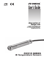
OS210 SERIES
IR Temperature Sensors
User’s Guide
e-mail: [email protected]
For latest product manuals:
omegamanual.info
Shop online at
omega.com
TM
TM

Servicing North America:
Omega Engineering,
Toll-Free: 1-800-826-6342 (USA & Canada only)
Customer Service: 1-800-622-2378 (USA & Canada on
ly)
Engineering Service: 1-800-872-9436 (USA & Canada only)
Tel: (203) 359-1660 Fax: (203) 359-7700
e-mail: [email protected]
For Other Locations Visit omega.com/worldwide
omega.com [email protected]
The information contained in this document is believed to be correct, but OMEGA accepts no liability for
any errors it contains, and reserves the right to alter specifications without notice.
TM
U.S.A.
Headquarters:

3
›
english
OS210 non-contact infrared sensors measure temperatures from -20°C to 500°C and provide
either a linear 4 to 20 mA output, a voltage output or a thermocouple output. This range of
output signals is compatible with almost any indicator, controller, recorder, data logger etc.,
without the need for special interfacing or signal conditioning. They are suitable for most
materials such as food, paper, textiles, plastics, leather, tobacco, pharmaceuticals, chemicals,
rubber, coal and asphalt; but not materials with a low emissivity, for example polished metals.
OS210 sensors are available as either two-wire or four-wire units.
Two-wire OS210 sensors transmit the target temperature as a 4-20 mA output and offer a
simple solution for most non-contact temperature measurement applications.
Four-wire OS210 sensors transmit the target temperature as a 0-50 mV or thermocouple
output (type J, K or T) plus the internal sensor temperature as a 4-20 mA output. This second
output can be used to ensure that the sensor is being operated within the correct ambient
temperature limits and prevent damage caused by overheating or overcooling. It can also be
used to give an approximate indication of the air temperature surrounding the sensor.
SPECIFICATION
Model Numbers (X = output: see Output Table)
Field of View -20ºC to 100ºC 0ºC to 250ºC 0ºC to 500ºC
2:1 OS211-LT-X* OS211-MT-X* -
15:1 OS151-LT-X* OS151-MT-X* OS151-HT-X*
30:1 OS301LT-X* OS301-MT-X* OS301-HT-X*
ø5mm @ 100mm OS801LT-X* OS801MT-X* OS801HT-X*
* Output table
Model (-X) Target Temperature Output Sensor Temperature Output
(blank) 4-20 mA (two wire, loop powered) Not available
-MV 0-50 mV 4-20 mA
-T Type T thermocouple 4-20 mA
-J Type J thermocouple 4-20 mA
-K Type K thermocouple 4-20 mA
Example model number
OS151MT: OS210 infrared temperature sensor with 15:1 optics, temperature range 0°C to
250°C, two-wire 4-20 mA output
GENERAL
Accuracy ±1% of reading or ±1°C whichever is greater
Repeatability ±0.5% of reading or ±0.5°C whichever is greater
Emissivity 0.95 (fixed)
Response Time 240 ms (90% response)
Spectral Response 8 to 14 µm
Supply Voltage 24 V DC (28 V DC max.)
Sensor Voltage 6 V DC min.
Maximum Loop Impedance 900 ohms (4-20 mA output)
Output Impedance 56 ohms (voltage/thermocouple output)
MECHANICAL
Construction Stainless Steel
Dimensions 18 mm diameter x 103 mm
Cable Length 1 m as standard (up to 30 m available on request)
Weight with 1 m Cable 95 g
ENVIRONMENTAL
Environmental Rating IP65
Ambient Temperature Range 0°C to 70°C
Relative Humidity 95% maximum non-condensing

4
›
english
INSTALLATION
The installation process consists of the following stages:
Preparation Mechanical installation Electrical installation
Please read the following sections thoroughly before proceeding with the installation.
PREPARATION
Ensure that the sensor is positioned so that it is focused on the target only.
ACCESSORIES
A range of accessories to suit different applications and industrial environments is available.
These may be ordered at any time and added on-site. The accessories consist of the following
parts .
Fixed mounting bracket Adjustable mounting bracket Air purge collar
Laser sighting tool
OPTIONS
The following options are available. Options are factory installed and must be ordered with the
OS210.
Air/water cooled housing Certificate of calibration Longer cable (30m max.)
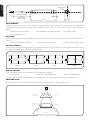
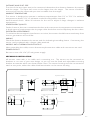
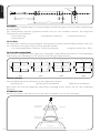
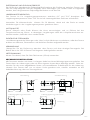
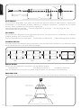
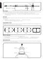
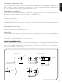
OPTICAL CHART
The optical chart below indicates the nominal target spot diameter at any given distance from
the sensing head and assumes 90% energy.
Standard length
1000
Longer lengths
available to order
103
12
18
M16 x 1mm
Distance: Sensor to object (inches)
Distance: Sensor to object (mm)
11.9
45.2
78.6
0.5
1.8
3.1
0 19.7 39.4
0
11.9
0
500 1000
Spot Dia.
(inches)
Spot Dia.
(mm)
Spot Dia.
(inches)
Spot Dia.
(mm)
Distance: Sensor to object (inches)
Distance: Sensor to object (mm)
Spot Dia.
(inches)
Spot Dia.
(mm)
Distance: Sensor to object (inches)
Distance: Sensor to object (mm)
11.9
0.5
61.9
111.9
0.5
2.4
4.4
048
0
0
5.0
0.20
100
3.9
12.5
0.49
200
7.9
100 200
D:S 15:1D:S 2:1
OS211 OS801OS151
Distance: Sensor to object (inches)
Distance: Sensor to object (mm)
11.9
28.6
45.2
0.5
1.1
1.8
0 19.7 39.4
0 500 1000
Spot Dia.
(inches)
Spot Dia.
(mm)
D:S 30:1
OS301
Sensor
CORRECT
INCORRECT
Background
Target greater
than spot size
Target smaller
than spot size

5
›
english
DISTANCE AND SPOT SIZE
The size of the area (spot size) to be measured determines the distance between the sensor
and the target. The spot size must not be larger than the target. The sensor should be
mounted so that the measured spot size is smaller than the target.
AMBIENT TEMPERATURE
The sensor is designed to operate in ambient temperatures from 0°C to 70°C. For ambient
temperatures above 70°C, an air/water-cooled housing will be required.
Avoid thermal shock. Allow 20 minutes for the unit to adjust to large changes in ambient
temperature.
ATMOSPHERIC QUALITY
Smoke, fumes or dust can contaminate the lens and cause errors in temperature measurement.
In these types of environment the air purge collar should be used to help keep the lens clean.
ELECTRICAL INTERFERENCE
To minimise electromagnetic interference or ‘noise’, the sensor should be mounted away from
motors, generators and such like.
WIRING
Check the distance between the sensor and the indicating/controlling device. If necessary, the
sensor can be ordered with a longer cable attached.
MODELS WITH THERMOCOUPLE OUTPUT
When extending the cable, ensure thermocouple extension cable and connectors are used.
POWER SUPPLY
Be sure to use a 24 V DC (25 mA) power supply.
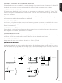
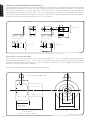
MECHANICAL INSTALLATION
All sensors come with a 1m cable and a mounting nut. The sensor can be mounted on
brackets or cut outs of your own design, or you can use the fixed and adjustable mounting
bracket accessories which are shown below. Note: The sensor housing must be connected to
earth at one point, either the cable shield termination or the sensor housing.
60° Rotation 60° Rotation
60° Rotation
Fixed Bracket Adjustable Bracket
2 x Mounting Holes M4 Clearance 2 x Mounting Holes M4 Clearance
12.0
45.0
50.0 50.0
40.0
9.0
15.0
25.0 25.0
9.0
48.0
9.0
24.024.0
Ø16.0

6
›
english
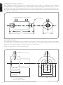
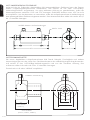
AIR/WATER COOLED HOUSING
The air/water cooled housing shown below allows the sensor to withstand high ambient
temperatures. It is equipped with two 1/8” BSP fittings. Water temperature should be 10°C to 27°C
for efficient cooling. Chilled water below 10°C is not recommended. To avoid condensation, the
air purge collar should be used with the water-cooled housing. Water flow rate should not be more
than 0.5 to 1.5 litres/min.
40.0
2119 63
103
M16 x 1mm
1/8 BSP water/air connections
1/8 BSP Air connection
25
OS210-APSW
(OS211)
50
OS210-APSN
(OS151, OS301, OS801)
20
29
40
AIR PURGE COLLAR
The air purge collar below is used to keep dust, fumes, moisture, and other contaminants away
from the lens. It must be screwed in fully. Air flows into the 1/8” BSP fitting and out of the front
aperture. Air flow should be no more than 5 to 15 litres/min.
Clean or ‘instrument’ air is recommended.

7
›
english
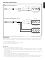
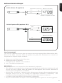
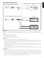
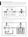
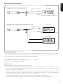
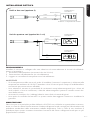
ELECTRICAL INSTALLATION
+-
-
+
Display/Controller
4-20mA = Target
4-20mA
Temperature
Power Supply
+-
-
+
4-20mA = Sensor
Temperature
Power Supply
-
+
mV/TC = Target
Temperature
Two-wire units (option 0)
Four-wire units (options 1 to 4)
OP-
OP+
PWR+
PWR-
PWR+
PWR-
Display/
Controller (optional)
Display/Controller
4-20mA
OPERATION
Once the sensor is in position and the appropriate power, air, water, and cable connections are
secure, the system is ready for continuous operation by completing the following simple steps:
1. Turn on the power supply
2. Turn on the meter, chart recorder or controller
3. Read / monitor the temperature
IMPORTANT
Be aware of the following when using the sensor:
• If the sensor is exposed to significant changes in ambient temperature (hot to cold, or cold to
hot), allow 20 minutes for the temperature to stabilise before taking or recording
measurements.
• Do not operate the sensor near large electromagnetic fields (e.g. around arc welders or
induction heaters).
Electromagnetic interference can cause measurement errors.
• Wires must be connected only to the appropriate terminals.
• Do not damage the cable, as this could provide a path for moisture and vapour into the sensor.
• Do not open the sensor housing. This will damage the sensor and invalidate the warranty.

8
›
english
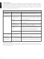
MAINTENANCE
Our customer service representatives are available for application assistance, calibration, repair,
and solutions to specific problems. Contact our Service Department before returning any
equipment. In many cases, problems can be solved over the telephone. If the sensor is not
performing as it should, try to match the symptom below to the problem. If the table does not
help, call Omega for further advice.
Troubleshooting
Symptom Probable Cause Solution
No output No power to sensor Check power supply and wiring
Inaccurate
measured
temperature
Target too small for
sensor’s field of view
Ensure the sensor’s view is completely filled
by the target. Position the sensor closer to
the target to measure a smaller area.
Target is a reflective
metal surface
Measure a non-reflective area, or paint or
coat a measurable area of the target to make
it non-reflective
Field of view
obstruction
Remove obstruction; ensure sensor has a
clear view of target
Dust or condensation
on lens
Ensure lens is clean and dry. Clean gently
with a soft lens cloth and water. If problem
recurs, consider using an air purge collar.
Incorrect wire
connections
Check wire colour codes
Erroneous
temperature
(mA or mV outputs)
Output temperature
scale mismatch
Re-scale input temperature range on
measurement instrument to match sensor
Erroneous
temperature
(thermocouple
output)
No Cold Junction
Compensation (CJC) or
wrong type of
extension cable
Enable CJC on measurement instrument;
ensure extension cable and connectors are
of the correct thermocouple type
LENS CLEANING
Keep the lens clean at all times. Any foreign matter on the lens would affect measurement
accuracy. Blow off loose particles (if not using the air purge accessory) with an air ‘puffer’.

9
›
français
Les pyromètres infra rouges de la série de OS210 mesurent des températures de -20ºC à
500ºC et possèdent une sortie linéaire 4..20mA, une Sortie tension ou une Sortie
thermocouple. Cette gamme des signaux de sortie est compatible avec la plus part des
indicateurs, contrôleurs, enregistreur, centrale d’acquisition de données etc., sans avoir
besoin d’interfaces ou de conditionnements de signal particuliers. Ils conviennent à la
plupart des matériaux tels que la nourriture, le papier, les textiles, les plastiques, le cuir, le
tabac, les produits pharmaceutiques, les produits chimiques, le caoutchouc, le charbon et
l’asphalte, exceptés les matériaux à faible émissivité, par exemple les métaux polis.
Les détecteurs OS210 sont disponibles en unités à deux ou à quatre fils.
Les détecteurs OS210 à deux fils transmettent la température cible sous forme d’une sortie
à 4-20 mA et représentent une solution simple pour la plupart des applications de mesure
de température sans contact.
Les détecteurs OS210 à quatre fils transmettent la température cible sous forme d’une sortie
à 0-50 mV ou thermocouple (type J, K ou T), ainsi que la température interne du détecteur
sous forme d’une sortie à 4-20 mA. On peut utiliser cette deuxième sortie afin de s’assurer
que le détecteur fonctionne en-deçà des limitations de température ambiante, et ainsi éviter
les dégâts potentiels causés par la surchauffe ou le refroidissement excessif. On peut l’utiliser
également pour obtenir une indication approximative de la température autour du
détecteur.
SPÉCIFICATIONS
Tableau montrant la gamme de températures vs le champ de vision
Champ de Visée -20ºC à 100ºC 0ºC à 250ºC 0ºC à 500ºC
2:1 OS211-LT-X* OS211-MT-X* -
15:1 OS151-LT-X* OS151-MT-X* OS151-HT-X*
30:1 OS301LT-X* OS301-MT-X* OS301-HT-X*
ø5mm @ 100mm OS801LT-X* OS801MT-X* OS801HT-X*
* Tableau des sorties
Model-X Température de sortie ciblée Température de détecteur ciblée
(vide) 4-20 mA –
-MV 0-50 mV 4-20 mA
-T T Thermocouple 4-20 mA
-J J Thermocouple 4-20 mA
-K K Thermocouple 4-20 mA
GÉNÉRALES
Précision ± 1% de la mesure ou ± 1°C, celui qui est le plus important
Fidélité ± 0,5% de la mesure ou ± 0,5°C, celui qui est le plus
important
Emissivité 0,95 (fixée)
Temps de réponse 240ms (réponse 90%)
Réponse spectrale 8 à 14µm
Voltage d’alimentation 24V cc (max. 28V cc)
Voltage du détecteur Min. 6V cc
Impédance en boucle maximale 900 Ohms (4-20mA sortie)
Impédance de Sortie 56 Ohms (Tension ou rendement de thermocouple)
MÉCANIQUES
Construction Acier inoxydable
Dimensions 18mm diamètre x 103mm
Longueur du câble 1m
Poids avec câble 95g
ENVIRONNEMENTALES
Catégorie environnementale IP65
Echelle de température ambiante 0°C à 70°C
Humidité relative Maximum 95% non condensée

10
›
français
Détecteur
LE MEILLEUR
PAS BON
Fond
Cible plus grand
que la grandeur
du point
Cible plus petit
que la grandeur
du point
INSTALLATION
Le processus d’installation consiste aux étapes suivantes :
Préparation Installation mécanique Installation électrique
Il faut lire les sections suivantes attentivement avant de commencer l’installation.
PRÉPARATION
S’assurer que le détecteur est mis en place pour qu’il ne se concentre que sur la cible.
ACCESSOIRES
Une gamme d’accessoires pour convenir aux différentes applications et environnements
industriels est disponible. Les accessoires peuvent être commandés à tout moment et ajoutés
sur place. Ils consistent en :
Un support de fixation fixe Un support de fixation réglable Un collier de purge d’air
Outil de visée Laser
OPTIONS
Les options suivantes sont disponibles : Les options sont installées en usine et doivent être
commandées avec le détecteur OS210.
Boîtier refroidi à l’air/eau Certificat de calibrage Câble plus long (30m max.)
TABLEAU OPTIQUE
Le tableau optique ci-dessous indique le diamètre du point cible nominal à n’importe quelle
distance de la tête de détection et assume 90% d’énergie.
1000
103
12
18
M16 x 1mm
Distance : Détecteur / objet (inches)
Distance : Détecteur / objet (mm)
11.9
45.2
78.6
0.5
1.8
3.1
0 19.7 39.4
0
11.9
0
500 1000
Diamètre
du point
(inches)
Diamètre
du point .
(mm)
Diamètre
du point
(inches)
Diamètre
du point .
(mm)
Distance : Détecteur / objet (inches)
Distance : Détecteur / objet (mm)
Diamètre
du point
(inches)
Diamètre
du point .
(mm)
Distance : Détecteur / objet (inches)
Distance : Détecteur / objet (mm)
11.9
0.5
61.9
111.9
0.5
2.4
4.4
048
0
0
5.0
0.20
100
3.9
12.5
0.49
200
7.9
100 200
D:S 15:1D:S 2:1
Distance : Détecteur / objet (inches)
Distance : Détecteur / objet (mm)
11.9
28.6
45.2
0.5
1.1
1.8
0 19.7 39.4
0 500 1000
Diamètre
du point
(inches)
Diamètre
du point .
(mm)
D:S 30:1
OS211 OS801OS151 OS301

11
›
français
DISTANCE ET TAILLE DU POINT
La taille de la zone (taille du point) qui doit être mesurée détermine la distance entre le
détecteur et la cible. La taille du point ne doit pas être plus grande que la cible. Le détecteur
devrait être monté de façon à ce que la taille du point mesuré est plus petite que la cible.
TEMPÉRATURE AMBIANTE
Le détecteur est conçu pour fonctionner en températures ambiantes de 0°C à 70°C. Pour les
températures ambiantes supérieures à 70°C, un boîtier refroidi à l’air/eau est nécessaire.
Eviter les chocs thermiques. Allouer 20 minutes au thermomètre, pour qu’il s’adapte à
d’importantes fluctuations de température ambiante.
QUALITÉ ATMOSPHÉRIQUE
La fumée, les vapeurs ou la poussière peuvent contaminer la lentille et provoquer des erreurs
dans la mesure de température. Dans ces genres d’environnement, le collier de purge d’air
devrait être utilisé pour aider à garder la lentille propre.
INTERFÉRENCE ÉLECTRIQUE
Pour réduire l’interférence électromagnétique ou ‘bruit’, le détecteur devrait être monté à
l’écart de moteurs, générateurs, et autres appareils similaires.
CÂBLAGE
Vérifier la distance entre le détecteur et l’appareil d’indication / de contrôle. Si nécessaire, le
détecteur OS210 peut être commandé avec un câble attaché plus long.
ALIMENTATION ÉLECTRIQUE
S’assurer qu’une alimentation électrique de 24Vcc (25mA) est utilisée.
INSTALLATION MÉCANIQUE
Tous les détecteurs sont fournis avec un câble d’un mètre et un boulon de fixation. Le
détecteur peut être monté sur un support ou sur des découpes de votre propre conception
ou bien les accessoires de support fixe et réglable, qui sont montrés ci-dessous, peuvent être
utilisés. Nota: Il faut que le détecteur soit connecté à la terre à un seul point, soit au blindage
du câble, soit au boîtier du détecteur.
12.0
45.0
50.0 50.0
40.0
9.0
15.0
25.0 25.0
9.0
48.0
9.0
24.024.0
Ø16.0
Rotation 60° Rotation 60°
Rotation 60°
Support fixe Support réglable
2 x trous de montage, jeu M4 2 x trous de montage, jeu M4

12
›
français
BOÎTIER REFROIDI À L’AIR/EAU
Le boîtier refroidi à l’air/l’eau montré ci-dessous permet au détecteur de resister à
des temperatures ambiantes élevées. Il est équipé de deux emmanchements de 1/8’’
BSP. La température de l’eau devrait être entre 10°C et 27°C pour un refroidissement
efficace. L’eau refroidie en dessous de 10°C n’est pas recommandée. Pour éviter la
condensation, le collier de purge d’air devrait être utilisé avec le boîtier refroidi à
l’eau. Le débit d’eau ne devrait pas dépasser 0,5 à 1,5 litres/min.
COLLIER DE PURGE D’AIR
Le collier de purge d’air ci-dessous est utilisé pour garder la poussière, les vapeurs, l’humidité
et autres contaminants à l’écart de la lentille. Il doit être entièrement vissé. L’air s’écoule dans
l’emmanchement de 1/8’’ BSP et sort par l’ouverture frontale. Le débit d’air ne devrait pas
dépasser 5 à 15 litres/min.
Il est recommandé d’utiliser de l’air propre ou pour les appareils.
40.0
2119 63
103
M16 x 1mm
1/8 BSP Raccords Air/Eau
20
29
40
1/8 BSP Raccord Air
25
OS210-APSW
(OS211)
50
OS210-APSN
(OS151, OS301, OS801)

13
›
français
INSTALLATION ÈLECTRIQUE
+-
-
+
4-20mA = Température cible
4-20mA
+-
-
+
4-20mA = Température détecteur
-
+
mV/TC = Température cible
Unités à deux fils (option 0)
Unités à quatre-fils (options 1 à 4)
OP-
OP+
PWR+
PWR-
PWR+
PWR-
4-20mA
Afficheur/
Contrôleur
Afficheur/
Contrôleur
Afficheur/
Contrôleur
Alimentation électrique
Alimentation électrique
FONCTIONNEMENT
Une fois que le détecteur est en place et que les connexions appropriées d’alimentation, d’air,
d’eau et de câbles sont bien fixées, le système est prêt pour fonctionner en continu en
complétant les simples étapes suivantes :
1. Mettre en route l’alimentation électrique
2. Mettre en route le compteur,
l’enregistreur de tableau ou le contrôleur
3. Lire / contrôler la temperature
IMPORTANT
Il faut faire attention aux suivants lors de l’utilisation du détecteur :
• Si le détecteur est exposé à des changements significatifs de température ambiante (chaud
à froid, ou froid à chaud), avant de prendre ou d’enregistrer des mesures attendre 20
minutes que la température se stabilise.
• Ne pas faire fonctionner le détecteur près d’importants champs électromagnétiques (par
exemple autour d’un arc de soudage ou d’appareils chauffants à induction). Des
interférences électromagnétiques peuvent provoquer des erreurs de mesure.
• Le câble ne doit être relié qu’à des terminaux appropriés.
• Ne pas ouvrir le boîtier du capteur. Cela endommagerait le capteur et annuler la garantie.

14
›
français
ENTRETIEN
Les représentants du service clientèle sont disponibles pour aider, calibrer, réparer et
résoudre des problèmes particuliers. Contacter le service technique avant de retourner
l’équipement. Dans beaucoup de cas, les problèmes peuvent être résolus par téléphone. Si le
détecteur ne fonctionne pas comme il le devrait, essayer de faire correspondre le symptôme
ci-dessous au problème. Si le tableau n’aide pas, appeler Omega pour plus de renseignement.
Diagnostic de défaillances
Symptôme Cause probable Solution
Pas de sortie Pas d’alimentation au
détecteur
Vérifiez l’alimentation et le câblage
Température
mesurée inexacte
Cible trop petite pour le
champ de vision du capteur
Assurez-vous que la vue du capteur est
complètement remplie par la cible.
Placez le capteur plus près de la cible
pour mesurer une zone plus petite.
La cible est une surface
métallique réfléchissante
Mesurer une zone non réfléchissante ou
peignez ou enduisez une zone
mesurable de la cible pour la rendre non
réfléchissante
Obstruction du champ de
vision
Enlever l’obstruction; Assurez-vous que
le capteur a une vision claire de la cible
Poussière ou condensation
sur la lentille
Assurez-vous que la lentille est propre et
sèche. Nettoyez délicatement avec un
chiffon doux et de l’eau. Si le problème
persiste, pensez à utiliser un collier de
purge d’air.
Connexions de fils
incorrectes
Vérifiez les codes de couleur des fils
Température
erronée (sorties
mA ou mV)
Disparité d’échelle de
température de sortie
Ré-échelle plage de température
d’entrée sur l’instrument de mesure pour
correspondre à capteur
Température
erronée (sortie du
thermocouple)
Aucune compensation de
soudure froide (CJC) ou
incorrect type de câble
d’extension
Activer CJC sur l’instrument de mesure;
Assurez-vous que le câble d’extension et
les connecteurs sont du bon type de
thermocouple
NETTOYAGE DE LA LENTILLE
Garder la lentille propre à tout moment. Toute matière étrangère sur la lentille affecterait la
précision de la mesure. Souffler les particules libres (si l’accessoire de purge d’air n’est pas
utilisé) avec un ‘soufflet’.

15
›
deutsch
Die kontaklosen Infrarot-Sensoren der OS210-Serie messen Temperaturen von -20ºC bis
500ºC und sind entweder mit einem linearen 4...20mA- Ausgang, einem Spannungsausgang
oder einem Thermoelement-Ausgang ausgestattet. Dieser Ausgangsbereich ist mit fast jedem
Anzeigegerät, Prozeßkontroller, Speicherschreiber, Datenlogger und ähnlichen Messumformern
kompatibel. Eine besondere Schnittstelle oder Signalverarbeitung ist nicht erforderlich. Die
Sensoren sind für die meisten Materialien wie Nahrungsmittel, Papier, Textilien, Kunststoffe,
Leder, Tabak, Arzneimittel, Chemikalien, Gummi, Kohle und Asphalt geeignet, nicht aber für
Materialien mit niedrigem Emissionsvermögen wie z. B. polierte Metalle.
OS210-Sensoren sind als Zweidraht- oder Vierdraht-Einheiten erhältlich.
Zweidraht-OS210-Sensoren übermitteln die Zieltemperatur als 4-20 mA-Ausgang und bieten
eine einfache Lösung für die meisten kontaktlosen Anwendungen zur Temperaturmessung.
Vierdraht-OS210-Sensoren übermitteln die Zieltemperatur als 0-50 mV- oder Thermoelement-
Ausgang (Typ J, K oder T) sowie die innere Sensortemperatur als 4-20 mA-Ausgang. Dieser
zweite Ausgang kann genutzt werden, um sicherzustellen, dass der Sensor innerhalb der kor-
rekten Grenzwerte für die Umgebungstemperatur genutzt wird, sowie um Schäden durch
Überhitzung oder Unterkühlung zu verhindern. Er kann auch genutzt werden, um einen
Näherungswert für die Temperatur der Luft um den Sensor zu erhalten.
SPEZIFIKATION
Temperaturbereich im Verhältnis zur Sichtfeldtabelle
Bildfeld -20ºC bis 100ºC 0ºC bis 250ºC 0ºC bis 500ºC
2:1 OS211-LT-X* OS211-MT-X* -
15:1 OS151-LT-X* OS151-MT-X* OS151-HT-X*
30:1 OS301LT-X* OS301-MT-X* OS301-HT-X*
ø5mm @ 100mm OS801LT-X* OS801MT-X* OS801HT-X*
* Ausgangstabelle
Modell-X Zieltemperaturausgang Sensortemperaturausgang
(leer) 4-20 mA –
-MV 0-50 mV 4-20 mA
-T T Thermoelement 4-20 mA
-J J Thermoelement 4-20 mA
-K K Thermoelement 4-20 mA
ALLGEMEIN
Messunsicherheit ±1% des Messwerts / ±1ºC (je nachdem, welcher Wert größe ist)
Wiederholgenauigkeit ±0,5% des Messwerts / ±0,5ºC (je nachdem, welcher Wert größer ist)
Emissionsvermögen 0,95 (festgelegt)
Reaktionszeit 240ms (90% Reaktion)
Spektralempfindlichkeit 8 bis 14µm
Speisespannung 24V Gleichstrom (28V Gleichstrom max.)
Sensorspannung 6V Gleichstrom min.
Maximale Kreis-Impedanz 900 Ohm (4-20mA Leistung)
Ausgangsimpedanz 56 Ohm (Spannung oder Thermoelementausgang)
MECHANISCHE DATEN
Konstruktion Rostfreier Stahl
Abmessungen 18mm Durchmesser x 103mm
Kabellänge 1m
Gewicht mit Kabel 95g
UMWELTBESTIMMUNGEN
Umwelttechnische Einstufung IP65
Umgebungstemperaturbereich 0ºC bis 70ºC
Relative Feuchte höchstens 95%, ohne Kondensation

16
›
deutsch
ZUBEHÖR
Eine Reihe von Zubehörteilen für unterschiedliche Anwendungen und industrielle Umgebungen
sind erhältlich.
Die Zubehörteilen können jederzeit bestellt und vor Ort installiert werden. Die folgenden
Zubehörteile sind lieferbar:
Feste Halterung Verstellbare Halterung Luftspülmanschette
Laserzielstrahl
OPTIONEN
Die folgenden Optionen sind verfügbar. Die Optionen werden werksmäßig installiert und müs-
sen zusammen mit dem OS210-Sensor bestellt werden.
Luft-/wassergekühltes Gehäuse Eichbescheinigung Längeres Kabel (max. 30m)
OPTISCHES DIAGRAMM
Das optische Diagramm unten gibt den nominellen Zielpunktdurchmesser in einer beliebigen
Entfernung vom Messkopf an. Es werden 90% Energie angenommen.
INSTALLATION
Der Installationsprozess besteht aus den folgenden Phasen:
Vorbereitung Mechanische Installation Elektrische Installation
Bitte lesen Sie sich die folgenden Abschnitte sorgfältig durch, bevor Sie mit der Installation
beginnen.
VORBEREITUNG
Achten Sie darauf, dass der Sensor nach dem Aufstellen nur auf das Ziel weist.
1000
103
12
18
M16 x 1mm
11.9
45.2
78.6
0.5
1.8
3.1
0 19.7 39.4
0
11.9
0
500 1000
(inches)
(mm)
Zielpunktdurchmesser
Entfernung zw. Sensor und Gegenstand
(inches)
Entfernung zw. Sensor und Gegenstand
(mm)
(inches)
(mm)
Zielpunktdurchmesser
Entfernung zw. Sensor und Gegenstand
(inches)
Entfernung zw. Sensor und Gegenstand
(mm)
(inches)
(mm)
Zielpunktdurchmesser
Entfernung zw. Sensor und Gegenstand
(inches)
Entfernung zw. Sensor und Gegenstand
(mm)
(inches)
(mm)
Zielpunktdurchmesser
Entfernung zw. Sensor und Gegenstand
(inches)
Entfernung zw. Sensor und Gegenstand
(mm)
11.9
0.5
61.9
111.9
0.5
2.4
4.4
048
0
0
5.0
0.20
100
3.9
12.5
0.49
200
7.9
100 200
D:S 15:1D:S 2:1
11.9
28.6
45.2
0.5
1.1
1.8
0 19.7 39.4
0 500 1000
D:S 30:1
OS211 OS801OS151 OS301
Sensor
AM BESTEN
FALSCH
Hintergrund
Ziel größer als
Zielpunktgröße
Ziel kleiner als
Zielpunktgröße

17
›
deutsch
ENTFERNUNG UND ZIELPUNKTGRÖSSE
Die Größe des Messbereichs (Zielpunktgröße) bestimmt die Entfernung zwischen Sensor und
Ziel. Die Zielpunktgröße darf die Zielgröße nicht übersteigen. Der Sensor sollte so aufgestellt
werden, dass die gemessene Zielpunktgröße kleiner ist als das Ziel.
UMGEBUNGSTEMPERATUR
Der Sensor ist für Umgebungstemperaturen zwischen 0°C und 70°C konzipiert. Bei
Umgebungstemperaturen über 70ºC ist ein luft-/wassergekühltes Gehäuse erforderlich.
Vermeiden Sie Wärmeschocks. Warten Sie 20 Minuten, damit sich das Gerät an starke
Veränderungen in der Umgebungstemperatur gewöhnen kann.
LUFTQUALITÄT
Rauch, Dämpfe oder Staub können die Linse verunreinigen und zu Fehlern bei der
Temperaturmessung führen. In derartigen Umgebungen sollte die Luftspülmanschette ver-
wendet werden, damit die Linse sauber bleibt.
ELEKTRISCHE STÖRUNGEN
Um elektromagnetische Störungen oder “Lärm” auf ein Minimum zu reduzieren, sollte der Sensor
entfernt von Motoren, Generatoren und ähnlichen Geräten aufgestellt werden.
VERKABELUNG
Überprüfen Sie die Entfernung zwischen dem Sensor und dem Anzeige-/Steuergerät. Bei
Bedarf kann der OS210-Sensor mit längerem Kabel geliefert werden.
NETZSPANNUNG
Achten Sie darauf, dass Sie 24V Gleichstrom (25mA) verwenden..
MECHANISCHE INSTALLATION
Alle Sensoren werden mit einem 1m langem Kabel und einer Befestigungsmutter geliefert. Der
Sensor kann an Halterungen oder mit lhrer eigenen Konstruktion befestigt werden. Oder ver-
wenden Sie die unten abgebildeten festen und verstellbaren Zubehörteile für die Halterung.
Hinweis: Der Sensor darf nur an einem Punkt geerdert sein, nämlich entweder an der
Kabelabschirmung oder am Sensorgehäuse.
60° Drehung 60° Drehung
60° Drehung
Feste Halterung Verstellbare Halterung
2 x Befestigungsbohrungen M4-Gewinde 2 x Befestigungsbohrungen M4-Gewinde
12.0
45.0
50.0 50.0
40.0
9.0
15.0
25.0 25.0
9.0
48.0
9.0
24.024.0
Ø16.0

18
›
deutsch
LUFT-/WASSERGEKÜHLTE GEHÄUSE
Aufgrund des im Folgenden dargestellten luft-/wassergekühlten Gehäuses kann der Sensor
hohen Umgebungstemperaturen standhalten. Der Sensor ist mit zwei 1/8-Zoll-Bsp-
Verbindungsstücken ausgestattet. Um eine wirksame Kühlung zu gewährleisten, sollte die
Wassertemperatur zwischen 10ºC und 27ºC betragen. Gekühltes Wasser unter 10ºC ist nicht
zu empfehlen. Um Kondensation zu vermeiden, sollte die Luftspülmanschette in Verbindung mit
dem wassergekühlten Gehäuse eingesetzt werden. Den Wasserdurchfluss sollte nicht mehr als 0,5
bis 1,5 Liter/Min. betragen.
LUFTSPÜLMANSCHETTE
Die unten abgebildete Luftspülmanschette hält Staub, Dämpfe, Feuchtigkeit und andere
Verunreinigungen von der Linse fern. Die Manschette muss vollständig eingeschraubt werden.
Luft strömt in das 1/8-Zoll-Bsp-Verbindungsstück und aus der vorderen Öffnung. Der
Luftstrom sollte nicht mehr als 5 bis 15 Liter/Min. betragen.
Es wird reine Luft oder “Hilfsluft” empfohlen.
40.0
2119 63
103
M16 x 1mm
1/8-BSP-Wasser-/Luftverbindungen
20
29
40
1/8-BSP-Luftverbindung
25
OS210-APSW
(OS211)
50
OS210-APSN
(OS151, OS301, OS801)

19
›
deutsch
ELEKTRISCHE INSTALLATION
+-
-
+
4-20 mA = Zieltemperatur
4-20mA
+-
-
+
4-20 mA = Sensortemperatur
-
+
mV/TC = Zieltemperatur
Zweidraht-Einheiten (Option 0)
Vierdraht-Einheiten (Optionen 1 bis 4)
OP-
OP+
PWR+
PWR-
PWR+
PWR-
Display/Controller
4-20mA
Stromzuführung
Stromzuführung
Display/
Controller
Display/
Controller
BETRIEB
Wenn der Sensor aufgestellt ist und die entsprechenden Strom-, Luft-, Wasser- und Kabelanschlüsse
gesichert sind, kann das System mit den folgenden einfachen Schritten auf Dauerbetrieb eingestellt
werden:
1. Die Stromversorgung einschalten
2. Das Messgerät, den Rekorder
oder Messumformer einschalten
3. Die Temperatur ablesen / überwachen
WICHTIG
Achten Sie beim Einsatz des Sensors auf die folgenden Punkte:
• Wenn der Sensor erheblichen Temperaturschwankungen ausgesetzt wird (heiss/kalt oder kalt/
heiss), sind 20 Minuten notwendig, damit sich die Temperatur vor der Temperaturmessung und
-aufzeichnung stabilisieren kann.
• Betreiben Sie den Sensor nicht in der Nähe großer elektromagnetischer Felder (z.B. von
Lichtbogenschweißgeräten oder Induktionsheizgeräten). Elektromagnetische Störungen können
zu Messfehlern führen.
• Die Kabel dürfen nur mit den korrekten Anschlüssen verbunden werden.
• Öffnen Sie das Sensorgehäuse nicht. Dadurch wird der Sensor beschädigt werden und die
Garantie erlischt.
WARTUNG
Unsere Kundendienstmitarbeiter können bei Anwendungen, kalibrierung, Reparaturen und Lösung
konkreter Probleme helfen. Setzen Sie sich bitte mit unserer Kundendienstabteilung in
Verbindung, bevor Sie Geräte zurücksenden. Häufig können Probleme telefonisch gelöst
werden.Wenn der Sensor nicht ordnungsgemäß funktioniert, versuchen Sie, das unten aufgefüh-
rte Symptom dem entsprechenden Problem zuzuordnen. Wenn die Tabelle nicht weiterhilft,
kann Ihnen Omega möglicherweise telefonisch weitere Tipps geben.

20
›
deutsch
Störungssuche
Symptom Wahrscheinliche
Ursache
Lösung
Kein Ausgangs-
signal
Keine Stromversorgung
am Sensor
Überprüfen Sie die Stromversorgung und
Verkabelung
Ungenaue
gemessene
Temperatur
Ziel zu klein für das
Sichtfeld des Sensors
Stellen Sie sicher, dass die Sicht des Sensors
vollständig vom Ziel ausgefüllt ist. Positionieren
Sie den Sensor näher am Ziel, um einen klei-
neren Bereich zu messen.
Ziel ist eine reflektiere-
nde Metalloberfläche
Messen Sie einen nicht reflektierenden Bereich
oder malen oder beschichten Sie einen mess-
baren Bereich des Ziels, um es nicht reflektiere-
nd zu machen
Sichtfeld Behinderung Entfernen Sie das Hindernis; Stellen Sie sicher,
dass der Sensor eine klare Sicht auf das Ziel hat
Staub oder
Kondensation auf der
Linse
Stellen Sie sicher, dass die Linse sauber und
trocken ist. Reinigen Sie vorsichtig mit einem
weichen Tuch und Wasser. Wenn das Problem
erneut auftritt, sollten Sie einen Luftspülkragen
verwenden.
Falsche
Kabelverbindungen
Überprüfen Sie die Drahtfarbencodes
Fehlerhafte
Temperatur (mA
oder mV
Ausgänge)
Abweichung der
Ausgangs-
temperaturskala
Skalieren Sie den Eingangstemperaturbereich
am Messgerät entsprechend dem Sensor
Fehlerhafte
Temperatur
(Thermo-
element-aus-
gang)
Keine Cold Junction
Compensation (CJC)
oder falscher Typ des
Verlängerungskabels
CJC am Messinstrument aktivieren; Stellen Sie
sicher, dass das Verlängerungskabel und die
Stecker vom richtigen Thermoelementtyp sind
REINIGEN DER LINSE
Halten Sie die Linse stets sauber. Fremdkörper auf der Linse würden die Messgenauigkeit beein-
trächtigen. Blasen Sie lose Partikel mit einem Gebläse von der Linse (sofern Sie nicht die
Luftspülmanschette verwenden).
La pagina si sta caricando...
La pagina si sta caricando...
La pagina si sta caricando...
La pagina si sta caricando...
La pagina si sta caricando...
La pagina si sta caricando...
La pagina si sta caricando...
La pagina si sta caricando...
La pagina si sta caricando...
La pagina si sta caricando...
La pagina si sta caricando...
La pagina si sta caricando...
La pagina si sta caricando...
La pagina si sta caricando...
La pagina si sta caricando...
La pagina si sta caricando...
-
 1
1
-
 2
2
-
 3
3
-
 4
4
-
 5
5
-
 6
6
-
 7
7
-
 8
8
-
 9
9
-
 10
10
-
 11
11
-
 12
12
-
 13
13
-
 14
14
-
 15
15
-
 16
16
-
 17
17
-
 18
18
-
 19
19
-
 20
20
-
 21
21
-
 22
22
-
 23
23
-
 24
24
-
 25
25
-
 26
26
-
 27
27
-
 28
28
-
 29
29
-
 30
30
-
 31
31
-
 32
32
-
 33
33
-
 34
34
-
 35
35
-
 36
36


Omega OS210 Series Manuale del proprietario
- Tipo
- Manuale del proprietario
in altre lingue
- English: Omega OS210 Series Owner's manual
- français: Omega OS210 Series Le manuel du propriétaire
- español: Omega OS210 Series El manual del propietario
- Deutsch: Omega OS210 Series Bedienungsanleitung
Documenti correlati
-
Omega OS150-USB Serie Manuale del proprietario
-
Omega OS212 Series Manuale del proprietario
-
-
-
-
-
-
-
-