HK Audio L SUB 1200 A Manuale utente
- Categoria
- Altoparlanti della soundbar
- Tipo
- Manuale utente
Questo manuale è adatto anche per

LINEAR SUB
L SUB 1200 A • L SUB 1500 A • L SUB 1800 A
L SUB 2000 A • L SUB 4000 A
Manual 1.6 V2
• English • Français• Deutsch • Italiano • Español

Version 2.6 10/2017
Important Safety Instructions!
Read before connecting!
This product has been built by the manufacturer in accordance with
IEC 60065 and left the factory in safe working order. To maintain this
condition and ensure non-risk operation, the user must follow the
advice and warning comments found in the operating instructions. If
this product shall be used in vehicles, ships or aircraft or at altitudes
exceeding 2000 m above sea level, take care of the relevant safety
regulations which may exceed the IEC 60065 requirements.
WARNING: To prevent the risk of fire and shock hazard, do not
expose this appliance to moisture or rain. Do not open case – no user
serviceable parts inside. Refer service to qualified service personnel.
This symbol, wherever it appears, alerts you to the presence
of uninsulated dangerous voltage inside the enclosure – voltage that
may be sufficient to constitute a risk of shock.
This symbol, wherever it appears, alerts you to the presence
of externally accessible hazardous voltage. External wiring connected
to any terminal marked with this symbol must be a “ready made
cable” complying with the manufacturers recommendations, or must
be a wiring installed by instructed persons only.
This symbol, wherever it appears, alerts you to important
operating and maintenance instructions in the accompanying
literature. Read the manual.
This symbol, wherever it appears, tells you: Take care! Hot
surface! To prevent burns you must not touch.
All electrical and electronic products including batteries
should be disposed of separately from the municipal waste stream via
designated collection facilities appointed by the government or the
local authorities.
Read these instructions. Keep these instructions. Follow all
warnings and instructions marked on the product and in this manual.
• Do not use this product near water. Do not place the product near
water, baths, wash basins, kitchen sinks, wet areas, swimming pools
or damp rooms.
• Do not place objects containing liquid on the product – vases,
glasses, bottles etc.
• Clean only with dry cloth.
• Do not remove any covers or sections of the housing.
• The set operating voltage of the product must match the local mains
supply voltage. If you are not sure of the type of power available
consult your dealer or local power company.
• Before connecting the device, please ensure that the mains supply
you are using is equipped with adequate protection against short
circuiting and grounding faults when the device is plugged in.
• To reduce the risk of electrical shock, the grounding of this product
must be maintained. Use only the power supply cord provided with
this product, and maintain the function of the center (grounding)
pin of the mains connection at any time. Make sure the mains outlet
used provides a proper protective ground connection.
• Do not defeat the safety purpose of the polarized or grounding-type
plug. A polarized plug has two blades with one wider than the other.
A grounding type plug has two blades and a third grounding prong.
The wide blade or the third prong are provided for your safety. If the
provided plug does not fit into your outlet, consult an electrician for
replacement of the obolete outlet.
• Protect the power cord from being walked on or pinched particularly
at plugs, convenience receptacles, and the point where they exit
from the device! Power supply cords should always be handled
carefully. Periodically check cords for cuts or sign of stress,
especially at the plug and the point where the cord exits the device.
• Never use a damaged power cord.
• Unplug this product during lightning storms or when unused for long
periods of time.
• This product can be fully disconnected from mains only by pulling
the mains plug at the unit or the wall socket. The product must be
placed in such a way at any time, that disconnecting from mains is
easily possible.
• Fuses: Replace with IEC127 (5x20mm) type and rated fuse for best
performance only! It is prohibited to use “patched fuses” or to short
the fuse-holder. Replacing any kind of fuses must only be carried
out by qualified service personal.
• Refer all servicing to qualified service personnel. Servicing is
required when the unit has been damaged in any way, such as:
- When the power cord or plug is damaged or frayed.
- If liquid has been spilled or objects have fallen into the product.
- If the product has been exposed to rain or moisture.
- If the product does not operate normally when the operating
instructions are followed.
- If the product has been dropped or the cabinet has been damaged.
• Do not connect external speakers to this product with an impedance
lower than the rated impedance given on the product or in this
manual. Use only cables with sufficient cross section according to
the local safety regulations.
• Keep away from direct sunlight.
• Do not install near heat sources such as radiators, heat registers,
stoves or other devices that produce heat.
• This apparatus is for moderate climates areas use, not suitable for
use in tropical climates countries.
• Do not block any ventilation openings. Install in accordance with
manufacturer’s instructions. This product must not be placed in
a built-in installation such as a rack unless proper ventilation is
provided.
• Always allow a cold device to warm up to ambient temperature,
when being moved into a room. Condensation can form inside it and
damage the product, when being used without warming up.
• Do not place naked flame sources, such as lighted candles on the
product.
• The device must be positioned at least 20 cm/8“ away from walls.
• Use only with the cart, stand, tripod, bracket or table specified by
the manufacturer or sold with the product. When a cart is used, use
caution when moving the cart/product combination to avoid injury
from tip-over.
• Use only accessories recommended by the manufacturer, this applies
for all kind of accessories, for example protective covers, transport
bags, stands, wall or ceiling mounting equipment. In case of
attaching any kind of accessories to the product, always follow the
instructions for use, provided by the manufacturer. Never use fixing
points on the product other than specified by the manufacturer.
• This appliance is NOT suitable to be used by any person or persons
(including children) with limited physical, sensorical or mental
ability, or by persons with insufficient experience and/or knowledge
to operate such an appliance. Children under 4 years of age must be
kept away from this appliance at all times.
• Never push objects of any kind into this product through cabinet
slots as they may touch dangerous voltage points or short out parts
that could result in risk of fire or electric shock.
• This product is capable of delivering sound pressure levels in excess
of 90 dB, which may cause permanent hearing damage! Exposure
to extremely high noise levels may cause a permanent hearing loss.
Wear hearing protection if continously exposed to such high levels.
• The manufacturer only guarantees the safety, reliability and
efficiency of this product if:
- Assembly, extension, re-adjustment, modifications or repairs are
carried out by the manufacturer or by persons authorized to do so.
- The electrical installation of the relevant area complies with the
requirements of IEC (ANSI) specifications.
- The unit is used in accordance with the operating instructions.
• This product is optimized for use with music and speech signals.
Using this product with sine wave, square wave or other kind of
measuring signals at higher level may lead to severe damage of the
product.
General Notes on Safety for Loudspeaker
Systems
Mounting systems may only be used for those loudspeaker
systems authorized by the manufacturer and only with the mounting
accessories specified by the manufacturer in the installation
instructions. Read and heed the manufacturer’s installation
instructions. The indicated load-bearing capacity cannot be
guaranteed and the manufacturer will not be liable for damages in the
event of improper installation or the use of unauthorized mounting
accessories.
The system’s load-bearing capacity cannot be guaranteed and
the manufacturer will not be liable for damages in the event that
loudspeakers, mounting accessories, and connecting and attaching
components are modified in any way.
Components affecting safety may only be repaired by the
manufacturer or authorized agents, otherwise the operating permit
will be voided.
Installation may be performed qualified personnel only,
and then only at pick-points with sufficient load-carrying capacity
and in compliance with local building regulations. Use only the
mounting hardware specified by the manufacturer in the installation
instructions (screws, anchors, etc.). Take all the precautions necessary
to ensure bolted connections and other threaded locking devices will
not loosen.
Fixed and portable installations (in this case, speakers
and mounting accessories) must be secured by two independent
safeties to prevent them from falling. Safeties must be able to
catch accessories or parts that are loose or may become loose.
Ensure compliance with the given national regulations when using
connecting, attaching, and rigging devices. Factor potential dynamic
forces (jerk) into the equation when determining the proper size and
load-bearing capacity of safeties.
Be sure to observe speaker stands’ maximum load-bearing
capacity. Note that for reasons of design and construction, most
speaker stands are approved to bear centric loads only; that is, the
speakers’ mass has to be precisely centered and balanced. Ensure
speaker stands are set up stably and securely. Take appropriate added
measures to secure speaker stands, for example when:
- the floor or ground surface does not provide a stable, secure base.
- they are extended to heights that impede stability.
- high wind pressure may be expected.
- there is the risk that they may be knocked over by people.
Special measures may become necessary as precautions against
unsafe audience behavior. Do not set up speaker stands in evacuation
routes and emergency exits. Ensure corridors are wide enough and put
proper barriers and markings in place when setting speaker stands up
in passageways. Mounting and dismounting are especially hazardous
tasks. Use aids suitable for this purpose. Observe the given national
regulations when doing so.
Wear proper protection (in particular, a helmet,
gloves, and safety shoes) and use only suitable means of ascent
(ladders, scaffolds, etc.) during installation. Compliance with this
requirement is the sole responsibility of the company performing the
installation.
WARNING!
After installation, inspect the system comprised
of the mounting fixtures and loudspeakers to ensure it is properly
secured.
The operator of loudspeaker systems (fixed or portable) must
regularly inspect or task a third party to regularly inspect all system
components in accordance with the given country’s regulations and
have possible defects repaired immediately.
We also strongly recommend maintaining a logbook or the like to
document all inspections.
When installing speakers for longer lasting or permanent outdoor
operation, be sure to take into account the stability and load-bearing
capacity of platforms and surfaces; loads and forces exerted by
wind, snow, and ice; as well as thermal influences. Also be sure to
provide sufficient safety margins for the rigging points used for flown
systems. Observe the given national regulations when doing so.
• Ask the manufacturer if your product is allowed for outdoor usage !
Professional loudspeaker systems can produce harmful
volume levels. Even prolonged exposure to seemingly harmless levels
(starting at about 95 dBA SPL) can cause permanent hearing damage!
Therefore we recommend that everyone who is exposed to high
volume levels produced by loudspeaker systems wears professional
hearing protection (earplugs or earmuffs).
Manufacturer: Stamer Musikanlagen GmbH, Magdeburger Str. 8,
66606 St. Wendel, Germany

LINEAR SUB 1.6
3
LINEAR SUB
Welcome to the HK Audio family!
Thank you for choosing a brand-name product made by our company. Rest
assured, we engineered and built it with the greatest care so it will serve
you well for many tomorrows to come.
Even if your experience with sound systems runs deep, some things about
this product are sure to be new to you. This is why we ask that you do not
set this manual aside without reading it fi rst. Be sure to keep it in a safe
place for later reference.
Here‘s wishing you the best sound at every occasion!
Your HK Audio team
Warranty
Use the convenient online registration option at www.hkaudio.com.
http://warranty.hkaudio.com
The registration is only valid if the device is registered via Internet
within 30 days of the date of purchase.
HK AUDIO
Technischer Service
Postfach 1509
66595 St. Wendel, Germany
Fax: +49 6851 905 100
• English • Deutsch • Français • Italiano • Español
L SUB 1200 A L SUB 1500 A
L SUB 2000 A L SUB 1800 A L SUB 4000 A

LINEAR SUB 1.6
4
1 Control Features
Serial No.
LINEAR SUB
1500 A
MADE IN GERMANY
Leave enough space for proper ventilation!
Power
Mains
Green = On
Red = Limit/Error
On
O
HK Audio is a brand of
Stamer Musikanlagen GmbH
Magdeburger Str. 8
66606 St. Wendel
Germany
Line Out
Mid/High
Thru
Input
Serial No.
LINEAR SUB
1800 A
MADE IN GERMANY
Leave enough space for proper ventilation!
Power
Mains
Green = On
Red = Limit/Error
On
O
HK Audio is a brand of
Stamer Musikanlagen GmbH
Magdeburger Str. 8
66606 St. Wendel
Germany
Line Out
Mid/High
Thru
Input
Line Out
Mid/High
Input
LR
Thru
LR
Gain Bass
+6 dB–6 dB
180°
0°
120 Hz
100 Hz
Configuration X-Over Bass Phase
Line Out
Mid/High
Input
LR
Thru
LR
Gain Bass
+6 dB–6 dB
180°
0°
120 Hz
100 Hz
Configuration X-Over Bass
off
on
Auto Sleep
Phase
Caution: Risk of electric
shock! Do not open!
Refer servicing to
qualified service
personnel.
220-240 V~
50-60 Hz
3 A rated current
Caution: To reduce
the risk of electric
shock, grounding of
the center pin of
this plug must be
maintained.
Caution: Risk of electric
shock! Do not open!
Refer servicing to
qualified service
personnel.
220-240 V~
50-60 Hz
3 A rated current
Caution: To reduce
the risk of electric
shock, grounding of
the center pin of
this plug must be
maintained.
HK Audio is a brand of Stamer Musikanlagen GmbH
.BHEFCVSHFS4USŦ4U8FOEFMŦ(FSNBOZ
HK Audio is a brand of Stamer Musikanlagen GmbH
.BHEFCVSHFS4USŦ4U8FOEFMŦ(FSNBOZ
220-240 V~
50-60 Hz
3.3 A rated current
Caution: To reduce
the risk of electric
shock, grounding of
the center pin of
this plug must be
maintained.
Leave enough space for proper ventilation!
Line Out
Mid/High
Input
LR
LR
LR
Thru
Power
Gain Bass
+6 dB–6 dB
0 dB
LimitPower
180°
0°
120 Hz
100 Hz
Configuration X-Over Bass Phase
LINEAR SUB
2000 A
MADE IN GERMANY
Leave enough space for proper ventilation!
Mains
1
1
2 3
4 5 7
8
9
10
2 3
4 5 7
8
1
4 5 7
8
9
10
9
10
13
13
11
12
13
14
14
14
15
1
4 5 7
8
9
10
11
12
13
14
On Off
Auto Sleep

LINEAR SUB 1.6
5
1 Gain Bass
This knob adjusts the subwoofer’s volume. When set to the 12 o’clock
position (0 dB /center-notched), the subwoofer’s volume is matched to the
LINEAR active speakers’ levels to achieve a balanced soundscape with an
evenhanded distribution of low and midrange frequencies. If you want to
increase or decrease the subwoofer’s volume, simply rotate the knob to the
left or right (control range +/-6 dB).
2 Power LED (L SUB 1200 A, L SUB 2000 A, L SUB 4000 A)
This LED lights up green when the Power button is set to On and mains
power is provided
3 Limit LED (L SUB 1200 A, L SUB 2000 A, L SUB 4000 A)
This LED lights up red when the power amp’s input signal is too high or a
fault has been detected. The LED briefl y fl ashes red to tell you the limiter is
responding to signal peaks.
Caution! If the Limit LED stays red while the unit is up and running, it
is being overloaded. Turn down the signal level! If you are not routing a
signal in and the Limit LED stays red, the system has detected a fault.
4 Confi guration
Set the switch to this position to confi gure one LINEAR active sub for
use with one LINEAR active speaker.
Set the switch to this position to operate two LINEAR active sub with
one LINEAR active speaker. In this setting, the levels of the two Line Out
Mid/High outputs are boosted by up to 6 dB to bring up the one mid/ high
unit’s level and balance it out with two LINEAR active subs.
5 X-Over Bass
The X-Over switch lets you adjust the upper corner frequency of the X-over
built into the LINEAR active sub.
• L SUB 1200 A between 110 Hz and 130 Hz
• L SUB 1500 A, L SUB 1800 A, L SUB 2000 A between 100 Hz and 120 Hz
Your choice of setting will depend on the conditions in the venue and the
type of audio signal.
6 Mode (L SUB 4000 A only)
The Mode switch lets you adjust the upper corner frequency of the X-over
built into the LINEAR active sub.
• L SUB 4000 A between 70 Hz (Sublow) and 100 Hz (Sub)
Your choice of setting will depend on the conditions in the venue and the
type of audio signal, as well as whether the subwoofer is being used as a
sub-low supplement or as a system bass.
7 Phase
The Phase switch confi gures the LINEAR active sub’s phase position to
match that of the connected mid/ high units (0°/180°). Set the switch to 0°
when operating the bass bin with LINEAR mid/ high units. You may have to
invert the phase 180° to operate it with other speakers.
Note:
• ELEMENTS setup:
E 110 Sub A/AS + L SUB 1500 A -> Phase = 180°
(X-Over Bass = 100 Hz)
E 210 Sub AS + L SUB 1800 A -> Phase = 180° (X-Over Bass = 100 Hz)
8 Line Out Mid/High L/R
Use these two electronically balanced XLR outputs to connect active mid/
high units.
9 Input L/R
This electronically balanced, combination XLR/ 6.3 mm (1/4") input accepts
audio signals.
10 Thru L/R
This parallel output routes Input L/R’s incoming signal back out.
11 Auto Sleep (L SUB 1500 A, L SUB 1800 A)
The built-in amp switches to standby mode (Consumption around 0.5
watts) when the button is set to „On“ and the unit does not receive a signal
for 180minutes. To power the subwoofer back up again, simply set its
Power button to „O “ for fi ve seconds and then back to On. The subwoofer
will remain up and running if you disable Auto Sleep by setting this button
to „O “.
• English • Deutsch • Français • Italiano • Español
HK Audio is a brand of Stamer Musikanlagen GmbH
.BHEFCVSHFS4USŦ4U8FOEFMŦ(FSNBOZ
Caution: To reduce the risk of electric
shock, grounding of the center pin of
this plug must be maintained.
220-240 V~
50-60 Hz
3.3 A rated
current
Sub
Sub Low
180°
0°
Mains
Power
Gain Bass
Line Out
Mid/High
Input
Thru
+6 dB–6 dB
0 dB
LimitPower
Leave enough space for proper ventilation!
LR
LR
LR
LINEAR SUB
4000 A
MADE IN GERMANY
Configuration Mode Phase
1
2 3
4 6 7
8
9
10
13
14

LINEAR SUB 1.6
6
12 Status LED (L SUB 1500 A, L SUB 1800 A)
This LED lights up green when the Power button is set to On and the unit is
getting mains power.
This LED lights up red when the power amp’s input signal is too high or a
fault has been detected. The LED briefl y fl ashes red to tell you the limiters
are responding to signal peaks.
Heads up! If the Limit LED stays red while the unit is up and running, it
is being overloaded. Turn down the signal level! If you are not routing a
signal in and the Limit LED stays red, the system has detected a fault.
13 Power
This is the on/o button for the LINEAR active sub. Its status LED lights up
green when it is engaged.
14 Mains
Use the factory-included mains cord to connect this socket to a wall outlet.
Note: All LINEAR SUBs are equipped with V-Lock mains sockets. If you
use a VOLEX locking mains cord or another optionally available brand
with the same design, you can fi x the mains cord in place to prevent
accidental disconnection.
15 Speaker Out (L SUB 1200 A only)
This port serves to connect a passive L SUB 1200 (NL4, 2+ = Sub+ /
2- = Sub-).
Heads up: Do not connect any other device. If you do, it may be destroyed
along with L SUB 1200 A.
2 Connecting Cords
Use a microphone cord equipped with XLR connectors or 6.3 mm (1/4”) jack
plugs to send the signal from the audio source (master, monitor, line, or a
similar output) to the balanced L/R Inputs. Connect the active mid/ high
units to the XLR outputs labeled Line Out Mid/High. Use the two Thru L/R
ports to route the fullrange signal to other speakers.
3 Operating the Sub
• Ensure the LINEAR active sub’s Power switch is set to o .
Caution! Always make sure the local mains voltage matches the voltage
specifi ed on the LINEAR SUB. You may destroy its electronic components
if you connect it to the wrong mains voltage.
• Turn the Gain Bass knob to the 12 o’clock position (0 dB/ center-notched).
• Set the Confi guration switch accordingly to match the number of LINEAR
active subs you are using.
• Ensure all connected line sources are switched on before powering up.
First, switch on the connected mixer and all signal sources connected to
it, for example, keyboards, amps, e ects, and so forth. LINEAR active
speakers should always be connected to the Line Out Mid/high ports and
switched on after all other components are up and running. When you’re
ready to tear the rig down, please turn the LINEAR active speaker down by
rotating the Input A/B Gain knobs counterclockwise as far as they will go
and switch them o before powering down all other connected devices.
• When you fl ip the Power switch, the fan will briefl y start up (system
check) and stop after about fi ve seconds. The fan is temperature-
controlled. It kicks on only at very high volume levels and runs according
to the given temperature. The Status LED (L SUB 1200 A, L SUB 2000 A,
L SUB 4000 A) lights up red during the system check and will extinguish
unless a fault is detected.
L SUB 1500 A, L SUB 1800 A: The Status LED lights up red during the
system check, and then green if there is no malfunction and the unit is
getting mains power.
4 Settings
• Adjusting Volume Levels with the Gain Bass Knob
Use the Gain Bass knob to adjust the active subwoofer’s volume to suit the
venue and situation. If you want to increase or decrease the subwoofer’s
volume, simply turn this knob to the left or right (control range +/-6 dB).
If you hear distortion or the signal sounds saturated, fi rst check the signal
sources and, if possible, reduce the output signal level there.
• Adjusting the Corner Frequency:
With the X-Over Bass Switch
You can use this switch to adjust the LINEAR active sub’s frequency range
to match the signal you wish to render and/or the surroundings. The Line
Out Mid/High Left/Right outputs are not a ected by this setting.
With the Mode Switch (L SUB 4000 A only)
Use this switch to adjust the frequency response of the active LINEAR
subwoofer to the audio signal and the surroundings. The Line Out Mid/High
Left/Right outputs are not a ected by Mode changes.
If you add the L SUB 4000 A to an existing PA system as a deep bass
extension, Sub Low is the recommended setting. The LINEAR range’s
acoustic and phase-corrected tuning ensure that the L SUB 4000 A works
with every model available.
• Adjusting the Phase Position with the Phase Switch
You can use the Phase switch to adjust the LINEAR active sub’s phase
position to match that of the connected mid/ high unit (for more on this,
see section 1.7)

LINEAR SUB 1.6
7
5 Technical Specifi cations
Model L SUB 1200 A L SUB 1500 A L SUB 1800 A L SUB 2000 A L SUB 4000 A
Max. SPL@10% THD 126 dB half-space 129 dB half-space 130 dB half-space 132 dB half-space 135 dB half-space
Max. SPL Peak@10% THD 128 dB half-space 131 dB half-space 132 dB half-space 133 dB half-space 137 dB half-space
Max. SPL Calc. 129 dB half-space 132 dB half-space 133 dB half-space 135 dB half-space 138 dB half-space
Frequency response +/– 3 dB 55 Hz – X-Over 49 Hz – X-Over 42 Hz – X-Over 49 Hz – X-Over 31 Hz – X-Over
Frequency response –10 dB 38 Hz – X-Over 45 Hz – X-Over 38 Hz – X-Over 39 Hz – X-Over 39 Hz – X-Over
Power output 1,200 W 1,200 W 1,200 W 1,200 W 1,200 W
Amp/type Class D Class D Class D Class D Class D
Active protection circuits Under-voltage, thermal, short
circuit, and over-current
protection, Subsonic 24 dB/oct.
peak limiter
Under-voltage, thermal, short
circuit, and over-current
protection, Subsonic 24 dB/oct.
peak limiter
Under-voltage, thermal, short
circuit, and over-current
protection, Subsonic 24 dB/oct.
peak limiter
Under-voltage, thermal, short
circuit, and over-current
protection, Subsonic 24 dB/oct.
peak limiter
Under-voltage, thermal, short
circuit, and over-current
protection, Subsonic 24 dB/
oct. peak limiter
Bass woofer 2x 10" 1x 15" 1x 18" 2x 12" 1x 18"
Cut-off Frequency active 110/130 Hz variable with
24 dB/oct.
100/120 Hz variable with
24 dB/oct.
100/120 Hz variable with
24 dB/oct.
100/120 Hz variable with
24 dB/oct.
70/100 Hz variable with
24 dB/oct.
Audio ports 2x XLR Combo In bal., 2 x XLR
Thru bal., 2x XLR-Mid/High Out,
Speakon NL4 for 2nd passive
L Sub 1200 (2+ = Sub+ / 2- =
Sub-)
2x XLR Combo In bal., 2 x XLR
Thru bal., 2x XLR-Mid/High Out
2x XLR Combo In bal., 2 x XLR
Thru bal., 2x XLR-Mid/High Out
2x XLR Combo In bal., 2 x XLR
Thru bal., 2x XLR-Mid/High Out
2x XLR Combo In bal., 2 x
XLR Thru bal., 2x XLR-Mid/
High Out
Input sensitivity +4 dBu @ Gain Center click +4 dBu @ Gain center-notched +4 dBu @ Gain center-notched +4 dBu @ Gain center-notched +4 dBu @ Gain center-
notched
Mains connector 1x IEC socket with V-Lock cord
retainer
1x IEC socket with V-Lock cord
retainer
1x IEC socket with V-Lock cord
retainer
1x IEC socket with V-Lock cord
retainer
1x IEC socket with V-Lock
cord retainer
Power consumption 3.3 A / 220-240 V (6.6 A / 100-
120V) nominal according to EN
60065
3 A / 220-240 V (6 A / 100-
120V) nominal according to
EN 60065
3 A / 220-240 V (6 A / 100-
120V) nominal according to
EN 60065
3.3 A / 220-240 V (6.6 A /
100-120V) nominal according
to EN 60065
3.3 A / 220-240 V (6.6
A / 100-120V) nominal
according to EN 60065
Pole mount 2x M20 (K&M) 1x M20 (K&M) 1x M20 (K&M) 1x M20 (K&M) 2x M20 (K&M)
Grips 4x HK Audio MultiGrip 2x HK Audio MultiGrip 4x HK Audio MultiGrip 4x HK Audio MultiGrip 8x HK Audio MultiGrip
Housing Birch multiplex 15/18 mm,
9/13 ply
MDF 16 mm MDF 16 mm Birch multiplex 15/18 mm,
9/13 ply
Birch multiplex 15/18 mm,
9/13 ply
Front grille 2 mm metal grille 2 mm metal grille 2 mm metal grille 2 mm metal grille 2 mm metal grille
Finish Acrylic enamel, black Acrylic enamel, black Acrylic enamel, black Acrylic enamel, black Acrylic enamel, black
Optional accessories Protective cover, Satellite Add-On
M20 XLR, Speaker, mounting
pole M20, 100 mm casters,
tilt unit
Protective cover, Satellite Add-
On M20 XLR, Speaker, mounting
pole M20, 100 mm casters,
tilt unit
Protective cover, Satellite Add-
On M20 XLR, Speaker, mounting
pole M20, 100 mm casters,
tilt unit
Protective cover, Satellite
Add-On M20 XLR, Speaker,
mounting pole M20, 100 mm
casters, tilt unit
Protective cover, Satellite
Add-On M20 XLR, Speaker,
mounting pole M20, 100 mm
casters, tilt unit
Dimensions (WxHxD) 38 x 66.8 x 56 cm
14-31/32 x 26-19/64 x 22-3/64“
48,5 x 48,5 x 59,5 cm
19-3/32 x 19-3/32 x 23-27/64"
51,0 x 67,0 x 72 cm
20-5/64 x 26-3/8 x 28-11/32"
50.6 x 80.6 x 61 cm
19-11/16 x 31-47/64 x 24-1/64“
91 x 51 x 81 cm
35-3/4 x 20 x 31-25/32“
Weight 30.7 kg / 67.7 lbs. 29,8 kg / 65,7 lbs. 42 kg / 92,6 lbs. 46.2 kg / 101.9 lbs. 59 kg / 130,1 lbs.
6 Applications
See the appendix starting on page 32.
• English • Deutsch • Français • Italiano • Español
1. L SUB 4000/A horizontal
+ L SUB 4000
+ L5 LTS+ L SUB 2000
+ L SUB 4000 + L SUB 2000
+ L5 112 F+ L5 115 F+ L5 LTS
Front
Front
Front
Top view
Front
Front Front Front
Front
2. L SUB 4000/A upright
Gain A
Input A
Thru A
Gain B
Input B
Thru B
+6 dB
0 dB
+6 dB
0 dB
Gain A
Input A
Thru A
Gain B
Input B
Thru B
+6 dB
0 dB
+6 dB
0 dB
Line
Mic
Line
Mic
Left Right
L
Line Out
Mid/High
Input
LR
LR
R
Thru
Gain Bass
+6 dB–6 dB
0 dB
LimitPower
180°
0°
120 Hz
100 Hz
Configuration X-Over Bass Phase
L
Line Out
Mid/High
Input
LR
LR
R
Thru
Gain Bass
+6 dB–6 dB
0 dB
LimitPower
180°
0°
120 Hz
100 Hz
Configuration X-Over Bass Phase
L
Line Out
Mid/High
Input
LR
LR
R
Thru
Gain Bass
+6 dB–6 dB
0 dB
LimitPower
180°
0°
120 Hz
100 Hz
Configuration X-Over Bass Phase
L
Line Out
Mid/High
Input
LR
LR
R
Thru
Gain Bass
+6 dB–6 dB
0 dB
LimitPower
180°
0°
120 Hz
100 Hz
Configuration X-Over Bass Phase
Line Line

Version 2.6 10/2017
Wichtige Sicherheitshinweise!
Bitte vor Anschluss lesen!
Dieses Produkt wurde gemäß IEC 60065 hergestellt und hat das
Werk in einem sicheren, betriebsfähigen Zustand verlassen. Um
diesen Zustand zu erhalten und um einen gefahrlosen Betrieb zu
gewährleisten, ist es notwendig, dass der Benutzer die Empfehlungen
und Warnhinweise befolgt, die in der Betriebsanleitung zu finden
sind. Bei Einsatz dieses Produktes in Fahrzeugen, Schiffen oder
Flugzeugen, oder in Höhen oberhalb 2000 m Meereshöhe müssen
die entsprechenden Sicherheitsstandards zusätzlich zur IEC 60065
beachtet werden.
WARNUNG: Um das Risiko von Feuer oder Stromschlag zu verhüten,
darf dieses Gerät nicht Feuchtigkeit oder Regen ausgesetzt werden.
Öffnen Sie das Gehäuse nicht – im Inneren gibt es keine Bauteile,
die vom Benutzer wartbar sind. Die Wartung darf nur von einem
qualifiziertem Kundendienst durchgeführt werden.
Dieses Symbol, wo immer es erscheint, warnt Sie vor
gefährlicher, nicht isolierter Spannung im Gehäuse – Spannung, die
möglicherweise genügt, eine Stromschlaggefahr darzustellen.
Dieses Symbol, wo immer es erscheint, warnt Sie vor außen
zugänglicher, gefährlicher Spannung. Eine Verbindung zu jeder
Anschlussklemme, die mit diesem Symbol versehen ist, darf nur mit
konfektioniertem Kabel hergestellt werden, dass den Empfehlungen
des Herstellers genügt, oder mit Kabel, das von qualifiziertem
Personal installiert wurde.
Dieses Symbol, wo immer es erscheint, macht Sie auf
wichtige Bedienungs- und Wartungsanweisungen aufmerksam, die in
beiliegenden Unterlagen zu finden sind. Bitte lesen Sie das Handbuch.
Dieses Symbol, wo immer es erscheint, sagt Ihnen: Vorsicht!
Heiße Oberfläche! Um Verbrennungen zu vermeiden, nicht anfassen.
Elektro- und Elektronikgeräte einschließlich Batterien sind
getrennt vom Hausmüll über offizielle Sammelstellen fachgerecht zu
entsorgen.
Bitte lesen Sie diese Anweisungen. Bewahren Sie diese
Anweisungen auf. Befolgen Sie alle Warnhinweise und Anweisungen
auf dem Gerät und in dieser Anleitung.
• Benutzen Sie dieses Gerät nicht in der Nähe von Wasser. Stellen Sie
das Gerät nicht in der Nähe von Wasser, Badewannen, Waschbecken,
Küchenspülen, nassen Stellen, Schwimmbecken oder in feuchten
Räumen auf.
• Stellen Sie keine Gefäße, wie Vasen, Gläser, Flaschen usw., die
Flüssigkeiten enthalten, auf das Gerät.
• Reinigen Sie das Gerät nur mit einem trockenen Tuch.
• Entfernen Sie keine Abdeckungen oder Teile des Gehäuses.
• Die auf dem Gerät angegebene Betriebsspannung muss mit der
örtlichen Spannung der Netzstromversorgung übereinstimmen.
Wenn Sie sich nicht sicher sind, welche Spannung in Ihrem Netz
zur Verfügung steht, konsultieren Sie bitte Ihren Händler oder den
örtlichen Stromversorger.
• Stellen Sie vor Anschluss des Gerätes unbedingt sicher, dass die
Netz versorgungsinstallation über ausreichende Schutz einrichtungen
gegen Kurzschluss und Erdungsfehler angeschlossener Geräte
verfügt.
• Um das Risiko eines Stromschlags zu verringern, muss die
Erdung des Gerätes beibehalten werden. Verwenden Sie nur das
mitgelieferte Stromführungskabel und behalten Sie die Funktion
der seitlichen, geerdeten Schutzkontakte des Netzanschlusses
immer aufrecht. Stellen Sie sicher, dass das Gerät nur an Steckdosen
angeschlossen wird, die über eine ordnungsgemäß funktionierende
Schutzerde verfügen.
• Schützen Sie das Stromführungskabel vor Betreten und Quetschen,
besonders in der Nähe der Stecker, Gerätesteckdosen – und
dort, wo sie am Gerät austreten! Stromführungskabel sollten
immer vorsichtig behandelt werden. Kontrollieren Sie die
Stromführungskabel in regelmäßigen Abständen auf Einschnitte und
Anzeichen von Abnutzung, besonders in der Nähe des Steckers und
an der Verbindung zum Gerät.
• Benutzen Sie niemals ein beschädigtes Stromführungskabel.
• Ziehen Sie bei Gewittern den Stecker des Gerätes und wenn das
Gerät über einen längeren Zeitraum nicht benutzt wird.
• Dieses Gerät wird nur vollständig von Stromnetz getrennt, wenn der
Stecker vom Gerät oder aus der Steckdose gezogen wird. Das Gerät
sollte so aufgestellt werden, dass das Trennen vom Stromnetz leicht
möglich ist.
• Sicherungen: Ersetzen Sie Sicherungen nur mit dem Typ IEC127
(5x20mm) und dem korrekten Nennwert, um die optimale Leistung
zu gewährleisten! Es ist untersagt, kurzgeschlossene Sicherungen zu
verwenden oder den Sicherungshalter zu überbrücken. Sicherungen
dürfen nur von qualifiziertem Personal gewechselt werden.
• Alle Wartungsarbeiten sollten nur von qualifiziertem Personal
ausgeführt werden. Wartung ist notwendig, wenn das Gerät auf
irgendeine Weise beschädigt wurde, wie zum Beispiel:
- Wenn das Stromführungskabel oder der Stecker beschädigt oder
abgenutzt ist.
- Wenn Flüssigkeit oder Gegenstände in das Gerät gelangt sind.
- Wenn das Gerät Regen oder Feuchtigkeit ausgesetzt war.
- Wenn das Gerät nicht ordnungsgemäß funktioniert, obwohl die
Bedienungsanleitung beachtet wurde.
- Wenn das Gerät hingefallen ist oder das Gehäuse beschädigt wurde.
• Beim Anschluss von Lautsprechern an dieses Gerät darf die auf dem
Gerät oder in dieser Anleitung angegebene Mindestimpedanz nicht
unterschritten werden. Die verwendeten Kabel müssen entsprechend
den lokalen Regelungen über einen ausreichenden Querschnitt
verfügen.
• Halten Sie das Gerät vom Sonnenlicht fern.
• Installieren Sie das Gerät nicht in der Nähe von Wärmequellen, wie
zum Beispiel Heizkörper, Heizregister, Öfen oder anderen Geräten,
die Hitze erzeugen.
• Dieses Gerät wurde für die Verwendung in gemäßigten Klimazonen
entwickelt. Nicht geeignet zur Verwendung in tropischen Klimazonen.
• Verstopfen Sie nicht die Lüftungsöffnungen. Installieren Sie das
Gerät entsprechend der Anleitung des Herstellers. Das Gerät darf
nicht eingebaut werden – wie zum Beispiel in einen Gestellrahmen,
es sei denn, dass für angemessene Belüftung gesorgt wird.
• Ein kaltes Gerät sollte immer auf die Umgebungstemperatur
erwärmt werden, wenn es in einen Raum transportiert wird.
Es könnte sich Kondensation im Inneren bilden, die das Gerät
beschädigt, wenn es ohne vorherige Erwärmung benutzt wird.
• Stellen Sie keine offenen Flammen, wie brennende Kerzen, auf das
Gerät.
• Das Gerät sollte mindestens 20 cm von Wänden aufgestellt werden.
• Das Gerät darf nur mit Rollwagen, Ständern, Stativen, Tischen
oder Halterungen benutzt werden, die vom Hersteller spezifiziert
sind oder zusammen mit dem Gerät verkauft wurden. Wenn
ein Rollwagen benutzt wird, seien Sie vorsichtig, wenn Sie die
Rollwagen/Geräte-Kombination transportieren, um Verletzungen
durch Umkippen zu vermeiden.
• Verwenden Sie nur Zubehör, das vom Hersteller empfohlen ist. Das
gilt für alle Arten von Zubehör, wie zum Beispiel Schutzabdeckungen,
Transporttaschen, Ständer sowie Wand- und Deckenhalterungen.
Wenn Sie irgendein Zubehör am Gerät anbringen, befolgen Sie
immer die Anleitungen des Herstellers. Benutzen Sie nur die
Befestigungspunkte des Geräts, die vom Hersteller vorgesehen sind.
• Dieses Gerät ist NICHT geeignet für eine Person oder Personen
(einschließlich Kindern) mit eingeschränkten physischen,
sensorischen und geistigen Fähigkeiten, oder für Personen mit
unzulänglicher Erfahrung und/oder Fachkenntnis, um solch ein Gerät
zu bedienen. Kinder unter 4 Jahren sollten stets von diesem Gerät
fern gehalten werden.
• Es sollten keinerlei Gegenstände durch die Gehäuseschlitze
eingeführt werden, da dadurch gefährliche, spannungsführende
Bauteile berührt oder kurzgeschlossen werden können. Dies könnte
zu einer Feuer- oder Stromschlaggefahr führen.
• Dieses Gerät ist imstande, Schalldruckpegel von mehr als 90 dB zu
produzieren. Dies könnte zu einem dauerhaften Hörschaden führen!
Eine Belastung durch extrem hohe Geräuschpegel kann zu einem
dauerhaften Gehörverlust führen. Bei einer anhaltenden Belastung
durch solch hohe Pegel sollte ein Gehörschutz getragen werden.
• Der Hersteller gewährleistet die Sicherheit, Zuverlässigkeit und
Leistung des Gerätes nur unter folgenden Voraussetzungen:
- Einbau, Erweiterung, Neueinstellung, Modifikationen oder
Reparaturen werden vom Hersteller oder autorisiertem Personal
ausgeführt.
- Die elektrische Installation des betreffenden Bereiches entspricht
den Anforderungen der IEC (ANSI) Maßgaben.
- Das Gerät wird entsprechend der Bedienungsanleitung benutzt.
• Dieses Produkt ist auf die Verwendung mit Musik- und Sprach-
signalen optimiert. Verwendung mit Sinus-, Rechteck- oder anderen
Mess-Signalen bei höherem Pegel kann zu ernsten Beschädigungen
des Geräts führen.
Allgemeine Sicherheitshinweise
für Lautsprechersysteme
Befestigungssysteme dürfen ausschließlich für die vom
Hersteller freigegebenen Lautsprechersysteme und mit dem in der
Montageanleitung genannten Montage-Zubehör verwendet werden.
Die Montagehinweise des Herstellers sind dabei unbedingt zu
beachten. Bei unsachgemäßer Montage bzw. Verwendung von nicht
freigegebenem Montage-Zubehör kann die angegebene Belastung
nicht garantiert und keinerlei Haftung seitens des Herstellers
übernommen werden.
Sollten Änderungen an Lautsprechern, an Montage-Zubehör,
Verbindungs- und Befestigungselementen sowie Anschlagmitteln
vorgenommen werden, kann die Tragfähigkeit des Systems nicht
mehr garantiert werden und seitens des Hersteller keinerlei Haftung
übernommen werden.
Reparaturen an sicherheitsrelevanten Bauteilen dürfen nur vom
Hersteller oder Bevollmächtigten durchgeführt werden, andernfalls
erlischt die Betriebserlaubnis.
Die Installation darf ausschließlich durch Sachkundige und nur
an Montagepunkten mit ausreichender Tragfähigkeit, ggf. unter der
Berücksichtigung von Bauauflagen, erfolgen. Das vom Hersteller in der
Montageanleitung vorgeschriebene Befestigungsmaterial (Schrauben,
Dübel, etc.) muss verwendet werden. Schraubverbindungen müssen
durch geeignete Maßnahmen gegen Lösen gesichert sein.
Ortsfeste oder mobile Installationen (hier Lautsprecher
inkl. Montagezubehör) müssen durch zwei unabhängig voneinander
wirkende Einrichtungen gegen Herabfallen gesichert sein. Lose
Zusatzteile oder sich lösende Teile müssen durch geeignete
Einrichtungen aufgefangen werden können. Bei Verwendung von
Verbindungs- und Befestigungselementen sowie Anschlagmitteln sind
die nationalen Vorschriften zu beachten. Hinsichtlich der Bemessung
der Sicherungsmittel sind mögliche dynamische Belastungen
(Ruckkräfte) mit zu berücksichtigen.
Bei Stativen ist vor allem die maximale Traglast zu beachten.
Außerdem sind die meisten Stative aus konstruktiven Gründen nur
für das Tragen von genau zentrischer Belastung zugelassen. Stative
müssen standsicher aufgestellt werden. Stative sind durch geeignete
Maßnahmen zusätzlich zu sichern, wenn zum Beispiel:
- ihre Aufstandfläche keinen sicheren Stand zulässt,
- ihre Höhen die Standsicherheit einschränken,
- mit zu hohem Winddruck zu rechnen ist,
- damit zu rechnen ist, dass sie durch Personen umgestoßen werden.
Besondere Maßnahmen können auch zur Vorsorge gegen gefährdendes
Verhalten von Zuschauern erforderlich werden. Stative dürfen nicht
in Flucht- und Rettungswegen aufgestellt werden. Bei Aufstellung
in Verkehrswegen ist auf die erforderliche Breite der Wege und
auf ordnungsgemäße Absperrung sowie Kennzeichnung zu achten.
Beim Auf- und Absetzen ist eine besondere Gefährdung gegeben.
Hierzu sind geeignete Hilfsmittel zu verwenden. Es sind hierbei die
nationalen Vorschriften zu beachten.
Während der Montage ist geeignete
Schutzausrüstung (insbesondere Kopfschutz, Handschuhe und
Sicherheitsschuhe) zu tragen und es sind nur geeignete Aufstiegshilfen
(Leitern, Gerüste, etc.) zu verwenden. Die Verantwortung dafür liegt
alleine beim ausführenden Installationsbetrieb.
ACHTUNG! Nach der Montage ist die Aufhängung des System
aus Halterung und Lautsprecher auf sichere Befestigung zu überprüfen.
Der Betreiber von Lautsprechersystemen (ortsfest oder mobil) ist
verpflichtet, alle Systemkomponenten unter Berücksichtigung der
jeweils nationalen Regelungen regelmäßig zu überprüfen bzw. prüfen
zu lassen und mögliche Schäden unverzüglich beseitigen zu lassen.
Weiterhin raten wir dringend zu einer ausführlichen Dokumentation
aller Überprüfungsmaßnahmen in Prüfbüchern o.ä.
Bei längerem oder dauerhaftem Einsatz von Lautsprechern im
Freien sind für Standsicherheit und Tragfähigkeit von Aufbauten und
Flächen insbesondere auch die Windlasten, Schnee- und Eislasten
sowie thermische Einflüsse zu berücksichtigen. Insbesondere
die Lastaufnahmepunkte geflogener Systeme sollten hier mit
ausreichenden Sicherheitsreserven dimensioniert werden. Es sind
hierbei die nationalen Vorschriften zu beachten.
• Fragen Sie den Hersteller, ob Ihr Produkt für den Betrieb im Freien
geeignet ist.
Professionelle Lautsprechersysteme sind in der Lage,
gesundheitsschädliche Schallpegel zu erzeugen. Selbst die Einwirkung
scheinbar harmloser Schallpegel über einen längeren Zeitraum
kann zu bleibenden Schäden am Gehör führen (ab ca. 95dBA
SPL)! Daher raten wir für alle Personen, die durch den Betrieb von
Lautsprechersystemen dem Einfluss hoher Schallpegel ausgesetzt
sind, zum Tragen von professionellem Gehörschutz (Ohrstöpsel oder
Kapselgehörschutz).
Hersteller: Stamer Musikanlagen GmbH, Magdeburger Str. 8,
66606 St. Wendel, Deutschland

LINEAR SUB 1.6
9
L SUB 1200 A L SUB 1500 A
L SUB 2000 A L SUB 1800 A L SUB 4000 A
LINEAR SUB
Willkommen in der HK Audio Familie!
Vielen Dank, dass Sie sich für ein Markenprodukt aus unserem Hause ent-
schieden haben, das mit größter Sorgfalt für Sie entwickelt und gefertigt
wurde.
Auch wenn Sie bereits eingehende Erfahrungen mit Beschallungsanlagen
gesammelt haben – bei diesem Produkt wird es trotzdem einige Dinge
geben, die neu für Sie sind. Legen Sie deshalb diese Bedienungs anleitung
nicht ungelesen beiseite und bewahren Sie sie zur späteren Verwendung
auf.
Wir wünschen Ihnen allzeit besten Sound!
Ihr HK Audio Team
Garantie
Nutzen Sie die komfortable Online-Registrierung über www.hkaudio.com.
http://warranty.hkaudio.com
Die Registrierung ist nur gültig, wenn die Registrierung innerhalb
von 30 Tagen ab Kaufdatum über das Internet erfolgte
HK AUDIO
Technischer Service
Postfach 1509
66595 St. Wendel, Deutschland
Fax: +49 6851 905 100
• English • Deutsch • Français • Italiano • Español

LINEAR SUB 1.6
10
1 Bedienelemente
Serial No.
LINEAR SUB
1500 A
MADE IN GERMANY
Leave enough space for proper ventilation!
Power
Mains
Green = On
Red = Limit/Error
On
O
HK Audio is a brand of
Stamer Musikanlagen GmbH
Magdeburger Str. 8
66606 St. Wendel
Germany
Line Out
Mid/High
Thru
Input
Serial No.
LINEAR SUB
1800 A
MADE IN GERMANY
Leave enough space for proper ventilation!
Power
Mains
Green = On
Red = Limit/Error
On
O
HK Audio is a brand of
Stamer Musikanlagen GmbH
Magdeburger Str. 8
66606 St. Wendel
Germany
Line Out
Mid/High
Thru
Input
Line Out
Mid/High
Input
LR
Thru
LR
Gain Bass
+6 dB–6 dB
180°
0°
120 Hz
100 Hz
Configuration X-Over Bass Phase
Line Out
Mid/High
Input
LR
Thru
LR
Gain Bass
+6 dB–6 dB
180°
0°
120 Hz
100 Hz
Configuration X-Over Bass
off
on
Auto Sleep
Phase
Caution: Risk of electric
shock! Do not open!
Refer servicing to
qualified service
personnel.
220-240 V~
50-60 Hz
3 A rated current
Caution: To reduce
the risk of electric
shock, grounding of
the center pin of
this plug must be
maintained.
Caution: Risk of electric
shock! Do not open!
Refer servicing to
qualified service
personnel.
220-240 V~
50-60 Hz
3 A rated current
Caution: To reduce
the risk of electric
shock, grounding of
the center pin of
this plug must be
maintained.
HK Audio is a brand of Stamer Musikanlagen GmbH
.BHEFCVSHFS4USŦ4U8FOEFMŦ(FSNBOZ
HK Audio is a brand of Stamer Musikanlagen GmbH
.BHEFCVSHFS4USŦ4U8FOEFMŦ(FSNBOZ
220-240 V~
50-60 Hz
3.3 A rated current
Caution: To reduce
the risk of electric
shock, grounding of
the center pin of
this plug must be
maintained.
Leave enough space for proper ventilation!
Line Out
Mid/High
Input
LR
LR
LR
Thru
Power
Gain Bass
+6 dB–6 dB
0 dB
LimitPower
180°
0°
120 Hz
100 Hz
Configuration X-Over Bass Phase
LINEAR SUB
2000 A
MADE IN GERMANY
Leave enough space for proper ventilation!
Mains
1
1
2 3
4 5 7
8
9
10
2 3
4 5 7
8
1
4 5 7
8
9
10
9
10
13
13
11
12
13
14
14
14
15
1
4 5 7
8
9
10
11
12
13
14
On Off
Auto Sleep

LINEAR SUB 1.6
11
1 Gain Bass
In Mittenstellung (0 dB /Centerclick) ist die Lautstärke des Subwoofers an
die LINEAR-Aktivlautsprecher so angepasst, dass ein homogener Klangein-
druck mit ausgewogenem Bass und Mittelhochton-Anteil besteht. Durch
Drehen des Gain Bass-Reglers nach links oder rechts kann die Lautstärke
des Subwoofers bei Bedarf verringert bzw. erhöht werden (Regelbe-
reich+/–6dB).
2 Power-LED (L SUB 1200 A, L SUB 2000 A, L SUB 4000 A)
Diese LED leuchtet grün, wenn der Power-Schalter auf „On“ geschaltet ist
und eine Stromverbindung besteht.
3 Limit-LED (L SUB 1200 A, L SUB 2000 A, L SUB 4000 A)
Diese LED leuchtet rot, wenn das Einganssignal der Endstufe zu hoch ist
oder ein Fehler vorliegt. Ein kurzzeitiges Aufl euchten der LED zeigt das
Arbeiten des Limiters bei Pegelspitzen an.
Achtung! Leuchtet die Limt LED während dem Betrieb dauerhaft rot,
wird das System überfahren. Reduzieren Sie den Signalpegel! Wenn kein
Audiosignal anliegt und die Limit LED dauerhaft rot leuchtet, liegt ein
Fehler vor.
4 Confi guration
In dieser Schalterstellung ist ein LINEAR Aktiv-Sub für die Nutzung
mit einem LINEAR-Aktivlautsprecher optimiert.
Diese Schalterstellung ist für den Betrieb von zwei LINEAR Aktiv-Sub
mit einem LINEAR-Aktivlautsprecher optimiert. In dieser Schalterstellung
werden die Pegel der beiden Line Out Mid/High-Ausgänge angehoben um
bei der Nutzung von zwei LINEAR Aktiv-Sub und der daraus resultierenden
Maximalpegelerhöhung von 6 dB ein ausgewogenes Pegelverhältnis
zwischen Bass und Topteil zu erreichen.
5 X-Over Bass
Mit dem X-Over-Schalter können Sie die obere Trennfrequenz der integrier-
ten Frequenzweiche des LINEAR Aktiv-Sub einstellen.
• L SUB 1200 A zwischen 110 Hz und 130Hz
• L SUB 1500 A, L SUB 1800 A, L SUB 2000 A zwischen 100 Hz und 120Hz
Diese ist abhängig von den räumlichen Gegebenheiten und des verwende-
ten Audiosignals.
6 Mode (nur L SUB 4000 A)
Mit dem Mode-Schalter können Sie die obere Trennfrequenz der integrier-
ten Frequenzweiche des LINEAR Aktiv-Sub einstellen.
• L SUB 4000 A zwischen 70 Hz (Sublow) und 100 Hz (Sub)
Diese ist zum einen abhängig von räumlichen Gegebenheiten sowie des
verwendeten Audio-Signals und zum anderen vom Einsatz des Subwoofers
als Sublow-Ergänzung oder Systembass.
7 Phase
Mit dem Phasen-Schalter kann der LINEAR Aktiv-Sub auf die Phasenlage
der angeschlossenen Topteile angepasst werden (0°/180°). Im Betrieb mit
LINEAR-Aktivlautsprechern muss der Schalter auf 0° eingestellt werden.
Beim Betrieb mit anderen Lautsprechern ist unter Umständen eine Drehung
der Phase um 180° erforderlich.
Hinweis:
• ELEMENTS setup:
E 110 Sub A/AS + L SUB 1500 A -> Phase = 180°
(X-Over Bass = 100 Hz)
E 210 Sub AS + L SUB 1800 A -> Phase = 180° (X-Over Bass = 100 Hz)
8 Line Out Mid/High L/R
Zwei elektronisch symmetrierte XLR-Ausgangs buchsen zum Anschluss von
aktiven Topteilen.
9 Input L/R
Elektronisch symmetrierte, kombinierte XLR/Klinken-Eingangsbuchsen für
das Musiksignal.
10 Thru L/R
Paralleler Ausgang zur Weiterleitung der Eingangssignale (Input L/R).
HK Audio is a brand of Stamer Musikanlagen GmbH
.BHEFCVSHFS4USŦ4U8FOEFMŦ(FSNBOZ
Caution: To reduce the risk of electric
shock, grounding of the center pin of
this plug must be maintained.
220-240 V~
50-60 Hz
3.3 A rated
current
Sub
Sub Low
180°
0°
Mains
Power
Gain Bass
Line Out
Mid/High
Input
Thru
+6 dB–6 dB
0 dB
LimitPower
Leave enough space for proper ventilation!
LR
LR
LR
LINEAR SUB
4000 A
MADE IN GERMANY
Configuration Mode Phase
1
2 3
4 6 7
8
9
10
13
14
• English • Deutsch • Français • Italiano • Español

LINEAR SUB 1.6
12
11 Auto Sleep (L SUB 1500 A, L SUB 1800 A)
Bei Stellung „On“ schaltet die Endstufe – sofern 180 Minuten kein Signal
anliegt – in den Ruhezustand (Verbrauch etwa 0,5 Watt). Um den Sub-
woofer wieder in den Betriebszustand zu versetzen, schalten Sie ihn über
den Power-Schalter für 5 Sekunden aus und anschließend wieder ein. Auto
Sleep auf „O “ deaktiviert diese Funktion und der Subwoofer bleibt dauer-
haft in Betrieb.
12 Status-LED (L SUB 1500 A, L SUB 1800 A)
Diese LED leuchtet grün, wenn der Power-Schalter auf „On“ geschaltet ist
und eine Stromverbindung besteht.
Wenn das Eingangssignal der Endstufe zu hoch ist bzw. ein Fehler vorliegt,
leuchtet die LED rot. Ein kurzzeitiges rotes Aufl euchten zeigt das Arbeiten
der Limiter bei Pegelspitzen an.
Achtung! Leuchtet die Power/Limiter-LED während des Betriebs dau-
erhaft rot, ist das System überlastet. Reduzieren Sie den Signalpegel!
Wenn kein Audiosignal anliegt und die LED dauerhaft rot leuchtet, liegt
ein Fehler vor.
13 Power-Schalter
Der Ein/Aus-Schalter für den LINEAR Aktiv-Sub. In eingeschaltetem Zu-
stand leuchtet die Power-LED grün.
14 Mains
Verbinden Sie diese Anschlussbuchse mittels eines Kaltgeräte stromkabels
(im Lieferumfang enthalten) mit der Netzsteckdose.
Hinweis: Alle LINEAR Aktiv-Sub sind mit verriegelbaren V-Lock-Netzein-
gangsbuchsen ausgestattet. In Kombination mit einem verriegelbaren
Anschlusskabel (VOLEX oder baugleich, optional erhältlich) kann das
Netzkabel arretiert werden und so gegen versehentliches Herausrut-
schen gesichert werden.
15 Speaker Out (nur L SUB 1200 A)
Ausgangsbuchse zum Anschluss eines passiven L SUB 1200 (NL4,
2+ = Sub+ / 2- = Sub-).
Achtung: Werden andere Geräte angeschlossen, können diese, wie auch
der L SUB 1200 A zerstört werden.
2 Anschlüsse und Verkabelung
Schließen Sie die von Ihrem Mischpult kommenden Signalkabel (Master
Out, Monitor Out, Line Out o.ä.) an die symmetrierten Input-Buchsen L/R
mit einem XLR/Klinken-Mikrofonkabel an. Verbinden Sie die anzuschlie-
ßenden Aktivlautsprecher über die XLR-Ausgänge „Line Out Mid/High“.
Zum Weiterschleifen des Fullrange-Signals auf andere Boxen nutzen Sie die
beiden Through-Buchsen (Thru L/R).
3 Inbetriebnahme
• Achten Sie darauf, dass der LINEAR Aktiv-Sub ausgeschaltet ist.
Achtung! Achten Sie darauf, dass die Spannungsangabe des
LINEARAktiv-Subwoofers der Netzspannung entspricht. Der Anschluss
an eine falsche Netzspannung kann die elektronischen Elemente des
LINEARAktiv-Subwoofers zerstören.
• Drehen Sie den Gain Bass-Regler in die Mitte (0 dB /Centerclick).
• Stellen Sie den Confi guration-Schalter entsprechend der verwendeten
Anzahl von LINEAR Aktiv-Sub ein.
• Achten Sie darauf, dass alle übrigen angeschlossenen Komponenten schon
vorher in Betrieb sind. Sowohl das angeschlossene Mischpult als auch alle
mit ihm verbundenen Signalquellen wie Keyboards, Instrumentalverstär-
ker, E ekte usw. sollten eingeschaltet sein. LINEAR-Aktivlautsprecher
sollten immer an den „Line Out Mid/High“ Buchsen angeschlossen werden
und nach allen anderen Komponenten eingeschaltet werden. Beim Aus-
schalten bitte zuerst die LINEAR-Aktivlautsprecher abdrehen (Gain-Regler
der Inputs A/B nach links drehen) und vor allen anderen angeschlossenen
Geräten ausschalten.
• Nach dem Einschalten mit dem Power-Schalter läuft der Lüfter kurz an
(Systemcheck) und geht nach ca. 5 Sekunden aus. Der Lüfter ist tempe-
raturgesteuert. Er geht nur bei sehr hohen Lautstärken in Betrieb und
regelt sich temperaturabhängig. Während des Systemchecks leuchtet die
Limiter-LED (L SUB 1200 A, L SUB 2000 A, L SUB 4000 A) rot und erlischt
wenn kein Fehler vorliegt.
Für L SUB 1500 A, L SUB 1800 A: Während des Systemchecks leuchtet die
Status-LED rot – sie wird grün wenn kein Fehler vorliegt und Netzspan-
nung anliegt.
4 Einstellungen
• Lautstärkeanpassung mit dem Bass Gain-Regler
Passen Sie mit diesem Regler die Lautstärke des Aktiv-Subwoofers an die
jeweilige Beschallungssituation an. Durch Drehen des Gain Bass-Reglers
nach links oder rechts kann die Lautstärke des Subwoofers bei Bedarf
verringert bzw. erhöht werden (Regelbereich +/-6dB). Falls Verzerrungen
oder Übersteuerungen auftreten, überprüfen Sie die Signalquellen und
reduzieren Sie nach Möglichkeit dort das Ausgangssignal.
• Anpassung der Trennfrequenz mit dem Schalter:
X-Over Bass
Passen Sie den Übertragungsbereich des LINEAR Aktiv-Sub mit diesem
Schalter an das zu übertragende Signal bzw. an die Umgebung an. Die
Ausgänge „Line Out Mid/High Left/Right“ sind von dieser Einstellung nicht
betro en.
Mode (nur L SUB 4000 A)
Passen Sie den Übertragungsbereich des LINEAR Aktiv-Sub mit diesem
Schalter an das zu übertragende Signal bzw. an die Umgebung an. Die
Ausgänge „Line Out Mid/High Left/Right“ sind von dieser Einstellung nicht
betro en.
Wird ein bestehendes Beschallungssystem um den L SUB 4000 A für eine
Tiefbass-Erweiterung ergänzt, empfi ehlt sich die Schalterstellung Sublow.
Durch die akustisch, phasenkorrekte Abstimmung des Subwoofers zur
gesamten LINEAR-Serie spielt der L SUB 4000 A mit jedem Modell.
• Anpassen der Phasenlage mit dem Phase-Schalter
Passen Sie mit diesem Schalter die Phasenlage zwischen dem LINEAR
Aktiv-Sub und dem verwendeten Topteil an (siehe auch 1.7).

LINEAR SUB 1.6
13
5 Technische Daten
Modell L SUB 1200 A L SUB 1500 A L SUB 1800 A L SUB 2000 A L SUB 4000 A
Max. SPL@10% THD 126 dB Halfspace 129 dB Halfspace 130 dB Halfspace 132 dB Halfspace 135 dB Halfspace
Max. SPL Peak@10% THD 128 dB Halfspace 131 dB Halfspace 132 dB Halfspace 133 dB Halfspace 137 dB Halfspace
Max. SPL Calc. 129 dB Halfspace 132 dB Halfspace 133 dB Halfspace 135 dB Halfspace 138 dB Halfspace
Frequenzgang +/– 3 dB 55 Hz – X-Over 49 Hz – X-Over 42 Hz – X-Over 49 Hz – X-Over 31 Hz – X-Over
Frequenzgang –10 dB 38 Hz – X-Over 45 Hz – X-Over 38 Hz – X-Over 39 Hz – X-Over 39 Hz – X-Over
Gesamtleistung 1200 W 1200 W 1200 W 1200 W 1200 W
Endstufen Class D Class D Class D Class D Class D
Aktive Schutzschaltungen Undervoltage-Protection,
Thermoprotection, Short-
Circuit-Protection, Overcurrent-
Protection, Subsonic 24 dB/Okt.,
Peak-Limiter
Undervoltage-Protection,
Thermoprotection, Short-
Circuit-Protection, Overcurrent-
Protection, Subsonic 24 dB/Okt.,
Peak-Limiter
Undervoltage-Protection,
Thermoprotection, Short-
Circuit-Protection, Overcurrent-
Protection, Subsonic 24 dB/
Okt., Peak-Limiter
Undervoltage-Protection,
Thermoprotection, Short-
Circuit-Protection, Overcurrent-
Protection, Subsonic 24 dB/
Okt., Peak-Limiter
Undervoltage-Protection,
Thermoprotection, Short-
Circuit-Protection, Overcurrent-
Protection, Subsonic 24 dB/Okt.,
Peak-Limiter
Basslautsprecher 2x 10" 1x 15" 1x 18" 2x 12" 1x 18"
Trennfrequenz aktiv 110/130 Hz wählbar
mit 24dB/Okt.
100/120 Hz wählbar
mit 24 dB/Okt.
100/120 Hz wählbar
mit 24 dB/Okt.
100/120 Hz wählbar
mit 24 dB/Okt.
70/100 Hz wählbar
mit 24 dB/Okt.
Audioanschlüsse 2x XLR-In, 2x XLR-Thru, 2x XLR-
Mid/High-Out, Speakon NL4 für
zweiten passiven L Sub 1200
(2+ = Sub+ / 2- = Sub-)
2x XLR/Klinke-Kombi In symm.,
2x XLR Thru symm., 2x XLR
Line Out Mid/High
2x XLR/Klinke-Kombi In symm.,
2x XLR Thru symm., 2x XLR
Line Out Mid/High
2x XLR/Klinke-Kombi In symm.,
2x XLR Thru symm., 2x XLR
Line Out Mid/High
2x XLR/Klinke-Kombi In symm.,
2x XLR Thru symm., 2x XLR
Line Out Mid/High
Eingangsempfindlichkeit +4 dBu @ Gain Centerclick +4 dBu @ Gain Centerclick +4 dBu @ Gain Centerclick +4 dBu @ Gain Centerclick +4 dBu @ Gain Centerclick
Netzanschluss 1x Kaltgeräteanschluss mit
V-Lock Sicherungssystem
1x Kaltgeräteanschluss mit V-Lock
Sicherungssystem
1x Kaltgeräteanschluss mit
V-Lock Sicherungssystem
1x Kaltgeräteanschluss mit
V-Lock Sicherungssystem
1x Kaltgeräteanschluss mit
V-Lock Sicherungssystem
Leistungsaufnahme 3,3 A / 220-240 V (6,6 A / 100-
120V) Nenn-Stromverbrauch
nach EN 60065
3 A / 220-240 V (6 A / 100-120V)
Nenn-Stromverbrauch nach EN
60065
3 A / 220-240 V (6 A / 100-
120V) Nenn-Stromverbrauch
nach EN 60065
3,3 A / 220-240 V (6,6 A / 100-
120V) Nenn-Stromverbrauch
nach EN 60065
3,3 A / 220-240 V (6,6 A / 100-
120V) Nenn-Stromverbrauch
nach EN 60065
Hochständerflansch 2x M20 (K&M) 1x M20 (K&M) 1x M20 (K&M) 1x M20 (K&M) 2x M20 (K&M)
Griffe 4x HK Audio MultiGrip 2x HK Audio MultiGrip 4x HK Audio MultiGrip 4x HK Audio MultiGrip 8x HK Audio MultiGrip
Gehäuse Birke-Multiplex 15/18 mm,
9/13-fach
MDF 16 mm MDF 16 mm Birke-Multiplex 15/18 mm,
9/13-fach
Birke-Multiplex 15/18 mm,
9/13-fach
Frontgitter 2 mm Metallgitter 2 mm Metallgitter 2 mm Metallgitter 2 mm Metallgitter 2 mm Metallgitter
Oberfläche Acryllack, schwarz Acryllack, schwarz Acryllack, schwarz Acryllack, schwarz Acryllack, schwarz
Optionales Zubehör Schutzhülle, Satellite Add-On
M20 XLR, Distanzstange M20,
100 mm-Rollen, Tilt-Unit
Schutzhülle, Satellite Add-On M20
XLR, Distanzstange M20, 100 mm-
Rollen, Tilt-Unit
Schutzhülle, Satellite Add-On
M20 XLR, Distanzstange M20,
100 mm-Rollen, Tilt-Unit
Schutzhülle, Satellite Add-On
M20 XLR, Distanzstange M20,
100 mm-Rollen, Tilt-Unit
Schutzhülle, Satellite Add-On
M20 XLR, Distanzstange M20,
100 mm-Rollen, Tilt-Unit
Abmessungen (BxHxT) 38 x 66,8 x 56 cm
14-31/32 x 26-19/64 x 22-3/64"
48,5 x 48,5 x 59,5 cm
19-3/32 x 19-3/32 x 23-27/64"
51,0 x 67,0 x 72 cm
20-5/64 x 26-3/8 x 28-11/32"
50,6 x 80,6 x 61 cm
19-11/16 x 31-47/64 x 24-1/64“
91 x 51 x 81 cm
35-3/4 x 20 x 31-25/32“
Gewicht 30,7 kg / 67,7 lbs. 29,8 kg / 65,7 lbs. 42 kg / 92,6 lbs. 46,2 kg / 101,9 lbs. 59 kg / 130,1 lbs.
6 Anwendungen
Siehe im Anhang ab Seite 32.
• English • Deutsch • Français • Italiano • Español
1. L SUB 4000/A horizontal
+ L SUB 4000
+ L5 LTS+ L SUB 2000
+ L SUB 4000 + L SUB 2000
+ L5 112 F+ L5 115 F+ L5 LTS
Front
Front
Front
Top view
Front
Front Front Front
Front
2. L SUB 4000/A upright
Gain A
Input A
Thru A
Gain B
Input B
Thru B
+6 dB
0 dB
+6 dB
0 dB
Gain A
Input A
Thru A
Gain B
Input B
Thru B
+6 dB
0 dB
+6 dB
0 dB
Line
Mic
Line
Mic
Left Right
L
Line Out
Mid/High
Input
LR
LR
R
Thru
Gain Bass
+6 dB–6 dB
0 dB
LimitPower
180°
0°
120 Hz
100 Hz
Configuration X-Over Bass Phase
L
Line Out
Mid/High
Input
LR
LR
R
Thru
Gain Bass
+6 dB–6 dB
0 dB
LimitPower
180°
0°
120 Hz
100 Hz
Configuration X-Over Bass Phase
L
Line Out
Mid/High
Input
LR
LR
R
Thru
Gain Bass
+6 dB–6 dB
0 dB
LimitPower
180°
0°
120 Hz
100 Hz
Configuration X-Over Bass Phase
L
Line Out
Mid/High
Input
LR
LR
R
Thru
Gain Bass
+6 dB–6 dB
0 dB
LimitPower
180°
0°
120 Hz
100 Hz
Configuration X-Over Bass Phase
Line Line

Version 2.6 10/2017
Consignes de sécurité importantes! A lire avant
de se connecter!
Ce produit a été construit conformément à la norme IEC 60065 par
le fabricant et a quitté l’usine en bon état de marche. Pour garantir
son intégrité et un fonctionnement sans risque, l’utilisateur se doit
de suivre les conseils et les avertissements préconisés dans cette
notice d’utilisation. En cas d’utilisation de ce produit dans un véhicule
terrestre, un navire ou un avion, ou encore à une altitude supérieure à
2000 mètres, il convient de prendre en considération les normes de
sécurité suivantes, en plus de la norme IEC 60065.
ATTENTION: Afin d’éviter tout risque d‘incendie et d‘électrocution,
n‘exposez pas cet appareil à l’humidité ou à la pluie. N’ouvrez pas
le boîtier; les pièces se trouvant à l’intérieur ne nécessitent pas
d’entretien de la part des utilisateurs. Adressez-vous à un spécialiste
qualifié pour procéder à l‘entretien de l‘appareil.
Ce symbole, quel que soit l’endroit où il apparaît, vous signale
des pièces sous tension non isolées dans le boîtier. Une tension
suffisante pour présenter un risque d’électrocution.
Ce symbole, quel que soit l’endroit où il apparaît, vous signale
des pièces sous tension accessibles depuis l’extérieur du boîtier. Tous les
câbles extérieurs raccordés à un composant marqué de ce symbole
doivent être de type préfabriqués et conformes aux spécifications du
fabricant ou doivent avoir été installés par des spécialistes qualifiés.
Ce symbole, quel que soit l’endroit où il apparaît, vous signale
des instructions importantes relatives à l’utilisation ou l’entretien de
l’appareil à lire dans les documents l’accompagnant. Lisez la notice
d’utilisation.
Ce symbole, quel que soit l’endroit où il apparaît, vous signale
un risque de brûlure dû à une surface chaude. Ne touchez pas cette
surface afin d’éviter de vous brûler.
Tous les appareils électriques et électroniques y compris les
piles doivent être éliminés séparément des déchets ménagers auprès des
points de collecte officiels prévus à cet effet.
Lisez ces instructions. Conservez ces instructions. Prenez en
compte tous les avertissements et toutes les instructions mentionnés
sur le produit ou dans cette notice d’utilisation.
• N’utilisez pas ce produit à proximité de l’eau. Ne le placez pas près de
l’eau, d’une baignoire, d’un bassin, d’un évier, d’une surface humide,
d’une piscine ou d’une pièce humide.
• Ne mettez pas d’objet contenant du liquide sur l’appareil, par exemple,
un vase, un verre ou une bouteille, etc.
• Nettoyez-le exclusivement avec un chiffon sec.
• N’enlevez pas le boîtier, ne serait-ce que partiellement.
• La tension de fonctionnement de l’appareil doit être réglée de manière
à correspondre à la tension d’alimentation de l’endroit où vous vous
trouvez. Si vous n’êtes pas sûr de connaître la tension d’alimentation,
demandez à votre revendeur ou à la compagnie d’électricité locale.
• Avant de brancher l’appareil, assurez-vous systématiquement que
l’installation électrique (alimentation) dispose de systèmes de
protection suffisants contre les courts-circuits et les erreurs de mise à
la terre des appareils raccordés.
• Afin de réduire le risque d’électrocution, vous ne devez jamais
supprimer la mise à la terre de l’appareil. Utilisez uniquement le câble
d’alimentation fourni avec le produit et maintenez la broche centrale
de la prise (mise à la terre) en état de fonctionnement. Ne négligez
pas la sécurité offerte par les prises polarisées ou avec mise à la terre.
Assurez-vous que l’appareil est bien raccordé à une prise disposant
d’une terre de protection et que celle-ci est en ordre de marche.
• Protégez le câble d’alimentation afin d’éviter que quelqu’un marche
dessus ou qu’il soit pincé, notamment près de la prise, de la prise
murale ou à la sortie de l’appareil même! Les câbles d’alimentation
doivent être tout le temps maniés avec précaution. Vérifiez
régulièrement que le câble n’est pas fendu ou qu’il ne présente pas de
signe d’usure, en particulier près de la prise et à la sortie de l’appareil.
• N’utilisez jamais de câble d’alimentation usé.
• Débranchez l’appareil en cas d’orage ou si vous ne l’utilisez pas
pendant une longue période.
• Débranchez l’appareil uniquement en le tenant par la prise au niveau
de la prise murale ou de la rallonge. L’appareil doit être placé de telle
manière à ce qu’il puisse être débranché facilement à tout moment.
• Fusibles: si nécessaire, remplacez-les uniquement par des fusibles de
type IEC127 (5x20mm) afin de garantir une meilleure performance.
Il est interdit d’utiliser des fusibles bricolés ou de raccourcir le porte-
fusible. Seul un personnel qualifié est habilité à remplacer les fusibles.
• Confiez tous les travaux d’entretien à des spécialistes qualifiés.
Il est nécessaire d’effectuer de tels travaux lorsque l’unité a été
endommagée, comme par exemple dans les cas suivants:
- Lorsque le câble d’alimentation est endommagé ou effiloché.
- Si du liquide a pénétré ou un objet est tombé dans le boîtier.
- Si l’appareil a été exposé à la pluie ou à l’humidité.
- Si l’appareil ne fonctionne pas correctement alors que vous avez suivi
toutes les instructions à la lettre.
- Si l’appareil est tombé ou que le boîtier est endommagé.
• En cas de raccordement de haut-parleurs à cet appareil, il faut
veiller à ne pas descendre sous l’impédance minimale indiquée
sur ledit appareil ou dans la présente notice. Les câbles employés
doivent présenter une section suffisante, qui soit conforme aux
réglementations locales en vigueur.
• Ne l’exposez pas directement aux rayons du soleil.
• Ne l’installez pas à proximité d’une source de chaleur, telle qu’un
radiateur, une grille de chauffage, un four ou tout autre appareil
susceptible de produire de la chaleur.
• Cet appareil est conçu pour une utilisation dans des zones climatiques
modérées. Il n'est pas adapté pour une utilisation dans des pays à climat
tropical.
• Ne masquez pas les bouches d’aération. Installez l’appareil
conformément aux instructions du fabricant. Il ne doit pas être placé
dans un emplacement confiné, comme un rack ou une console, sauf si
une ventilation suffisante est garantie.
• Si vous déplacez l’appareil, attendez qu’il soit à température ambiante
avant de le démarrer, sinon de la condensation peut se former à
l’intérieur et endommager l’appareil.
• Ne posez pas de d’objet à flamme ouverte sur l’appareil, comme par
exemple une bougie allumée.
• L’appareil doit être placé à au moins 20cm/8“ pouces du premier mur.
• Utilisez l’appareil uniquement avec un chariot, un support, un trépied,
des fixations ou une table recommandés par le fabricant ou vendus
avec le produit. Si vous utilisez un chariot, maniez-le avec précaution
afin d’éviter tout risque de blessure s’il se renverse.
• Utilisez uniquement les accessoires recommandés par le fabricant.
Cette consigne concerne toute sorte d’accessoires, qu’il s’agisse
de couvercles de protection, de sacs de transport, de supports ou
de dispositifs de fixation au mur ou au plafond. Si vous fixez un
accessoire à l’appareil, suivez toujours les instructions d’utilisation
du fabricant. N’utilisez pas d’autres points de fixation que ceux
préconisés par le fabricant.
• Cet appareil NE convient PAS aux personnes dont les capacités
motrices, sensorielles ou mentales sont déficientes (y compris les
enfants) ou aux personnes ne disposant pas de l’expérience ou des
connaissances nécessaires pour faire fonctionner le présent appareil.
Cet appareil doit dans tous les cas et être tenu constamment hors de
portée des enfants de moins de quatre ans.
• N’insérez jamais d‘objets à travers les grilles du boîtier, car ils
pourraient toucher des pièces sous tension dangereuses ou provoquer
un court-circuit pouvant causer un risque d’incendie ou d’électrocution.
• Cet appareil est capable de délivrer un niveau de pression acoustique
de 90dB, pouvant ainsi causer des troubles irréversibles de l’audition!
L’exposition continue à une nuisance sonore peut provoquer une perte
d’audition permanente. Portez des protections auditives adéquates si
vous vous exposez de manière continue à un tel niveau de pression
acoustique.
• Le fabricant garantit la sécurité, la fiabilité et l’efficacité de
fonctionnement de son produit uniquement si:
- l’assemblage, l’extension, le réajustement, la modification ou la
réparation de l’appareil ont été effectués par le fabricant ou par des
personnes agréées pour ce genre de travaux.
- l’installation électrique concernée est conforme aux normes IEC (ANSI).
- l’unité est utilisée conformément aux instructions d’utilisation.
• Ce produit a été optimisé pour une utilisation avec des signaux
musicaux ou voix. Une utilisation avec des signaux sinusoïdaux,
rectangulaires ou autres signaux de mesure risque de l’endommager
gravement.
Consignes de sécurité générales pour systèmes
de haut-parleurs
Les systèmes de fixation doivent exclusivement être employés
pour les systèmes de haut-parleurs fournis par le fabricant et avec les
accessoires de montage tels qu’évoqués dans la notice de montage. Dans
ce cadre, il convient de respecter scrupuleusement les indications de
montage du fabricant. En cas d’utilisation non conforme d’accessoires ou
d’installation d’accessoires de montage non d’origine, le dommage en
résultant éventuellement ne sera pas couvert par la garantie et la
responsabilité du fabricant ne pourra en aucun cas être engagée.
Si des modifications sont apportées aux haut-parleurs, aux accessoires
de montage, aux raccords et fixations ainsi qu’au matériel d’élingage, la
portabilité du système ne pourra plus être garantie et la responsabilité
du fabricant ne pourra en aucun cas être engagée.
Toute réparation d’éléments de sécurité ne peut être effectuée que
par le fabricant ou son représentant agréé, faute de quoi le permis
d’exploitation s’éteint.
L’installation sera exclusivement réalisée par un spécialiste, et
ce, uniquement dans des zones de montage présentant une capacité de
charge suffisante, un point à vérifier notamment par la prise en compte
des normes de construction appliquées. Le matériel de fixation prescrit
par le constructeur dans la notice de montage (vis, chevilles, etc.) doit
impérativement être employé. Les raccords boulonnés doivent être
assurés contre tout desserrement au moyen de mesures appropriées.
Les installations fixes ou mobiles (ici les haut-parleurs,
accessoires de montage compris) doivent être assurés contre la chute
par deux dispositifs indépendants l’un de l’autre. Les éléments
supplémentaires lâches ou les pièces se desserrant doivent pouvoir être
retenus par des dispositifs adaptés. En cas d’utilisation de raccords,
d’éléments de fixation et de matériel d’élingage, il convient de respecter
les dispositions nationales en la matière. Le calcul du dimensionnement
des dispositifs de sécurité requiert la prise en compte des charges
dynamiques possibles (forces de recul).
En cas d’utilisation de trépieds, il faut surtout prendre en
considération la charge maximale supportée. En outre, de par leur
conception, la plupart des trépieds permettent uniquement de supporter
des charges parfaitement centrées. Les trépieds doivent dès lors être
disposés de façon stable. Il est nécessaire d’assurer les trépieds par des
mesures supplémentaires dans les cas suivants (liste non exhaustive) :
- lorsque leur surface de pose n’offre pas une stabilité suffisante;
- lorsque leur hauteur limite leur stabilité ;
- lorsque la force du vent risque d’être élevée ;
- lorsqu’ils risquent d’être heurtés par des personnes.
Des mesures particulières peuvent également s’avérer nécessaires, à titre
préventif, pour se prémunir contre des comportements dangereux de la
part de spectateurs. Les trépieds ne doivent donc pas être disposés dans
des voies d’évacuation ou des passages réservés aux secours. En cas
d’installation sur des voies de circulation, veiller à respecter la largeur
de circulation requise, à verrouiller le secteur de façon adaptée et à
mettre en place la signalisation idoine. Le montage et le démontage
sont des phases qui présentent des risques particuliers. Il faut dès lors
employer des moyens auxiliaires appropriés. Veiller également, lors de
ces opérations, à respecter la législation nationale en la matière.
Lors du montage, il est indispensable de porter
des équipements de sécurité adaptés (en particulier un casque, des
gants et des chaussures de sécurité) et d’utiliser uniquement des
dispositifs d’aide à l’ascension adaptés (échelles, échafaudages, etc.).
La responsabilité dans ce domaine incombe uniquement à la société de
montage exécutante.
ATTENTION! À l’issue du montage, il y a lieu de contre-vérifier la
fixation ou la suspension du système (haut-parleurs et supports).
L’exploitant des systèmes de haut-parleurs (fixes ou mobiles) est tenu
de vérifier, ou de faire vérifier, tous les composants du système en
fonction des réglementations en vigueur dans le pays concerné, et de
faire éliminer sans délai les éventuels défauts constatés.
En outre, nous recommandons fortement de constituer une
documentation détaillée sur toutes les mesures d’inspection dans les
registres de contrôle ou similaires.
En cas d’utilisation prolongée ou permanente de haut-parleurs en plein
air, tenir compte, pour la stabilité et la capacité portante des structures
et surfaces, de l’influence de paramètres tels le vent, la neige, la glace
et autres facteurs thermiques. Dans ce cas, il convient en particulier de
dimensionner avec des réserves de sécurité suffisantes les points de
support de charge de systèmes suspendus. Veiller également, lors de ces
opérations, à respecter la législation nationale en la matière.
• Adressez-vous au fabricant pour savoir si votre produit convient à un
usage en extérieur.
Les systèmes de haut-parleurs professionnels sont capables
de produire des niveaux sonores dangereux pour la santé. Même
des niveaux sonores a priori inoffensifs peuvent, en cas d’exposition
prolongée, provoquer des pertes auditives irréversibles (à partir
de 95 dBA SPL environ) ! C’est pourquoi nous conseillons à toutes
les personnes soumises à des niveaux sonores élevés en raison de
l’exploitation de systèmes de haut-parleurs, de porter des protections
auditives professionnelles (bouchons d’oreilles ou casques antibruit).
Fabricant : Stamer Musikanlagen GmbH, Magdeburger Str. 8,
66606 St. Wendel, Allemagne

LINEAR SUB 1.6
15
LINEAR SUB
Bienvenue dans la famille HK Audio!
Nous vous remercions d’avoir opté pour un produit de notre marque, produit
que nous avons développé et fabriqué pour vous, avec le plus grand soin.
Même si vous avez déjà une longue expérience des installations
de sonorisation, vous constaterez que ce produit a che certaines
caractéristiques qui seront nouvelles pour vous. C’est pourquoi nous
vous conseillons de lire la présente notice et de la conserver ensuite pour
consultation ultérieure.
Nous vous souhaitons le meilleur des sons!
L’équipe HK Audio
Garantie
Vous pouvez utiliser notre service d’enregistrement en ligne convivial sur
notre site www.hkaudio.com.
http://warranty.hkaudio.com
L’enregistrement est uniquement valable lorsqu’il est e ectué, sur Internet,
dans les 30 jours qui suivent la date d’achat.
HK AUDIO
Service technique
Postfach 1509
66595 St. Wendel, Allemagne
Fax: +49 6851 905 100
• English • Deutsch • Français • Italiano • Español
L SUB 1200 A L SUB 1500 A
L SUB 2000 A L SUB 1800 A L SUB 4000 A

LINEAR SUB 1.6
16
1 Commandes
Serial No.
LINEAR SUB
1500 A
MADE IN GERMANY
Leave enough space for proper ventilation!
Power
Mains
Green = On
Red = Limit/Error
On
O
HK Audio is a brand of
Stamer Musikanlagen GmbH
Magdeburger Str. 8
66606 St. Wendel
Germany
Line Out
Mid/High
Thru
Input
Serial No.
LINEAR SUB
1800 A
MADE IN GERMANY
Leave enough space for proper ventilation!
Power
Mains
Green = On
Red = Limit/Error
On
O
HK Audio is a brand of
Stamer Musikanlagen GmbH
Magdeburger Str. 8
66606 St. Wendel
Germany
Line Out
Mid/High
Thru
Input
Line Out
Mid/High
Input
LR
Thru
LR
Gain Bass
+6 dB–6 dB
180°
0°
120 Hz
100 Hz
Configuration X-Over Bass Phase
Line Out
Mid/High
Input
LR
Thru
LR
Gain Bass
+6 dB–6 dB
180°
0°
120 Hz
100 Hz
Configuration X-Over Bass
off
on
Auto Sleep
Phase
Caution: Risk of electric
shock! Do not open!
Refer servicing to
qualified service
personnel.
220-240 V~
50-60 Hz
3 A rated current
Caution: To reduce
the risk of electric
shock, grounding of
the center pin of
this plug must be
maintained.
Caution: Risk of electric
shock! Do not open!
Refer servicing to
qualified service
personnel.
220-240 V~
50-60 Hz
3 A rated current
Caution: To reduce
the risk of electric
shock, grounding of
the center pin of
this plug must be
maintained.
HK Audio is a brand of Stamer Musikanlagen GmbH
.BHEFCVSHFS4USŦ4U8FOEFMŦ(FSNBOZ
HK Audio is a brand of Stamer Musikanlagen GmbH
.BHEFCVSHFS4USŦ4U8FOEFMŦ(FSNBOZ
220-240 V~
50-60 Hz
3.3 A rated current
Caution: To reduce
the risk of electric
shock, grounding of
the center pin of
this plug must be
maintained.
Leave enough space for proper ventilation!
Line Out
Mid/High
Input
LR
LR
LR
Thru
Power
Gain Bass
+6 dB–6 dB
0 dB
LimitPower
180°
0°
120 Hz
100 Hz
Configuration X-Over Bass Phase
LINEAR SUB
2000 A
MADE IN GERMANY
Leave enough space for proper ventilation!
Mains
1
1
2 3
4 5 7
8
9
10
2 3
4 5 7
8
1
4 5 7
8
9
10
9
10
13
13
11
12
13
14
14
14
15
1
4 5 7
8
9
10
11
12
13
14
On Off
Auto Sleep

LINEAR SUB 1.6
17
1 Potentiomètre Gain Bass
Ce potentiomètre permet de régler le volume du subwoofer. En position
médiane (0 dB / clic central), le volume du caisson de basses est adapté
aux enceintes actives LINEAR de sorte qu’il procure une impression
d’homogénéité sonore grâce à l’équilibre basses/médiums-aigus. En
tournant le potentiomètre Gain Bass vers la gauche ou vers la droite, vous
pouvez, selon les besoins, réduire ou augmenter le volume sonore du
caisson de basses (plage de réglage: +/-6 dB).
2 DEL d‘alimentation (L SUB 1200 A, L SUB 2000 A, L SUB 4000 A)
Cette DEL s‘allume en vert lorsque l‘interrupteur marche/arrêt est sur
«On» et qu‘une connexion secteur est présente.
3 DEL de limite (L SUB 1200 A, L SUB 2000 A, L SUB 4000 A)
Cette DEL s‘allume en rouge lorsque le signal d‘entrée de l‘étage de sortie
est trop élevé ou qu‘un dysfonctionnement est présent. Si la DEL s‘allume
par intermittence, elle indique simplement l’intervention du limiteur en cas
de pic de niveau.
Attention! En revanche, si la DEL de limite reste rouge durablement alors
que l’appareil est en fonctionnement, c’est que le système subit une
surcharge. Vous devez alors absolument réduire le niveau de signal! De
même, si la DEL de limite reste allumée en rouge en permanence alors
qu’aucun signal audio n’est présent, c’est qu’il y a dysfonctionnement.
4 Commutateur de confi guration
Dans cette position, un sub actif LINEAR est optimisé pour une
utilisation avec un haut-parleur actif LINEAR.
Dans cette position, le commutateur assure l‘optimisation du fonc —
tion nement de deux sub actifs LINEAR et d‘un haut-parleur actif LINEAR.
Le commutateur permet alors de relever le niveau des deux sorties Line Out
Mid/High, ce qui permet d‘atteindre, en cas d‘utilisation de deux subs actifs
LINEAR (donc avec une augmentation du niveau maximal de 6dB), un
di érentiel de niveau équilibré entre caisson de basses et satellites.
5 Commutateur X-Over Bass
Le commutateur X-Over permet de régler la fréquence de coupure
supérieure du diviseur de fréquence intégré du subwoofer actif LINEAR.
• L SUB 1200 A entre 110 Hz et 130Hz
• L SUB 1500 A, L SUB 1800 A, L SUB 2000 A entre 100 Hz et 120Hz
Celle-ci dépend des conditions imposées par la salle et du matériel employé.
6 Commutateur Mode (uniquement L SUB 4000 A)
Le commutateur Mode permet de régler la fréquence de coupure supérieure
du diviseur de fréquence intégré du subwoofer actif LINEAR.
• L SUB 4000 A entre 70 Hz (Sublow) et 100 Hz (Sub)
Dépend d’une part des conditions d’utilisation (type de salle) et du signal
audio utilisé, et, d’autre part, de l’emploi du subwoofer en tant que
complément Sublow ou que basse système.
7 Commutateur de phase
Le commutateur de phase permet d‘adapter le sub actif LINEAR à la
position de phase des satellites raccordés (de 0° à 180°). En cas d‘utilisation
avec des satellites LINEAR, il doit être ramené à 0°. En cas d‘utilisation
avec d‘autres haut-parleurs, il peut s‘avérer nécessaire, dans certaines
circonstances, de pousser la phase à 180°.
Remarque :
• ELEMENTS setup:
E 110 Sub A/AS + L SUB 1500 A -> Phase = 180°
(X-Over Bass = 100 Hz)
E 210 Sub AS + L SUB 1800 A -> Phase = 180° (X-Over Bass = 100 Hz)
8 Sorties Line Out Mid/High L/R
Il s‘agit de deux douilles de sortie XLR (gauche/droite) symétrisées
électroniquement, prévues pour le raccordement de satellites actifs.
9 Entrées Input L/R
Douilles d’entrée XLR/jack combinées (gauche/droite) symétrisées
électroniquement, accueillant le signal musical.
10 Sorties Thru L/R
Sorties parallèles pour la transmission des signaux d‘entrée gauche/droite
(Input L/R).
• English • Deutsch • Français • Italiano • Español
HK Audio is a brand of Stamer Musikanlagen GmbH
.BHEFCVSHFS4USŦ4U8FOEFMŦ(FSNBOZ
Caution: To reduce the risk of electric
shock, grounding of the center pin of
this plug must be maintained.
220-240 V~
50-60 Hz
3.3 A rated
current
Sub
Sub Low
180°
0°
Mains
Power
Gain Bass
Line Out
Mid/High
Input
Thru
+6 dB–6 dB
0 dB
LimitPower
Leave enough space for proper ventilation!
LR
LR
LR
LINEAR SUB
4000 A
MADE IN GERMANY
Configuration Mode Phase
1
2 3
4 6 7
8
9
10
13
14

LINEAR SUB 1.6
18
11 Fonction Auto Sleep (L SUB 1500 A, L SUB 1800 A)
En position «On», l’étage de sortie bascule en mode veille (consommation:
0,5watt environ), en l’absence de signal pendant 180minutes. Pour
ramener le subwoofer en mode de fonctionnement, coupez l’alimentation
au niveau de l’interrupteur marche/arrêt (Power) pendant 5 secondes,
puis rallumez. En position «O », la fonction Fonction Auto Sleep est
désactivée. En d’autres termes, le subwoofer reste activé en permanence.
12 DEL d’état (L SUB 1500 A, L SUB 1800 A)
Cette DEL s‘allume en vert lorsque l‘interrupteur marche/arrêt est sur
«On» et qu‘une connexion secteur est présente.
Cette DEL s‘allume en rouge lorsque le signal d‘entrée de l‘étage de sortie
est trop élevé ou qu‘un dysfonctionnement est présent. Si la DEL émet une
lumière rouge par intermittence, elle indique simplement l’intervention des
limiteurs en cas de pic de niveau.
Attention! Si la DEL Power/Limiter reste rouge durablement alors
que l’appareil est en fonctionnement, c’est que le système subit une
surcharge. Vous devez alors absolument réduire le niveau de signal! De
même, si la DEL reste allumée en rouge en permanence alors qu’aucun
signal audio n’est présent, c’est qu’il y a dysfonctionnement.
13 Interrupteur Power
Interrupteur marche/arrêt du sub actif LINEAR. Lorsque le système est
activé, la DEL d‘état s‘allume en vert.
14 Entrée Mains
Sur la prise secteur, branchez la fi che correspondante du cordon secteur
avec prise de terre (fourni avec l’appareil).
Remarque : Tous les subs actifs LINEAR sont équipés de prises d‘entrée secteur
verrouillables de type V-Lock. Le raccordement verrouillable (VOLEX ou de
conception similaire, disponible en option) permet d‘éviter tout débranchement
accidentel.
15 Sortie Speaker Out (uniquement L SUB 1200 A)
Douille de sortie pour le raccordement d‘un L SUB 1200 passif, (NL4,
2+ = Sub+ / 2- = Sub-).
Attention: Si d’autres appareils devaient être raccordés, ils pourraient
être détruits, au même titre que le L SUB 1200 A.
2 Raccordements et commandes
À l’aide d’un câble pour micro XLR/jack, raccordez les câbles de signaux
(Master Out, Monitor Out, Line Out ou autres), provenant de votre table
de mixage, aux prises d‘entrée Input L/R (gauche/droite) symétriques.
Raccordez les satellites actifs concernés via les sorties XLR Line Out Mid/
High. Pour poursuivre la boucle du signal total sur d‘autres enceintes, vous
utiliserez les deux douilles Through gauche/droite (Thru L/R).
3 Mise en service
• Assurez-vous que le sub actif LINEAR est coupé.
Attention! Veillez à ce que la tension indiquée sur le subwoofer actif
LINEAR corresponde à la tension secteur disponible. En e et, le
raccordement à une tension incorrecte peut entraîner la destruction des
composants électroniques du subwoofer actif LINEAR.
• Amenez le potentiomètre Gain Bass en position centrale (0 dBV /clic
central).
• Réglez le commutateur de confi guration en fonction du nombre de subs
actifs LINEAR employés.
• Veillez à ce que tous les autres composants raccordés soient
préalablement sous tension. Concrètement, la table de mixage
raccordée ainsi que toutes les autres sources de signal (claviers, amplis
d’instruments, e ets, etc.) doivent avoir été activés. Les haut-parleurs
actifs LINEAR doivent toujours être raccordés aux douilles Line Out Mid/
High. Ils doivent l‘être après branchement de tous les autres composants.
Inversement, au débranchement, couper d‘abord les haut-parleurs actifs
LINEAR (tourner vers la gauche le potentiomètre Gain des entrées A/B),
puis les débrancher avant tous les autres appareils raccordés.
• Après mise sous tension via l’interrupteur Power, le ventilateur tourne
brièvement (autocontrôle du système), puis se coupe après 5 secondes
environ. Le ventilateur est à déclenchement thermostatique. En d’autres
termes, il tourne uniquement en cas de volumes très élevés et se régule
ensuite en fonction de la température. Lors de la phase d‘autocontrôle du
système, la DEL du limiteur (L SUB 1200 A, L SUB 2000 A, L SUB 4000 A)
s‘allume en rouge, puis s‘éteint si aucun défaut n’est détecté.
L SUB 1500 A, L SUB 1800 A: Lors de la phase d’autocontrôle du système,
la DEL d’état s’allume d’abord en rouge, avant de passer au vert si aucun
défaut n’est détecté et si la tension secteur est disponible.
4 Réglages
• Adaptation du volume via le potentiomètre Gain Bass
Ce potentiomètre permet de régler le volume du subwoofer actif en
fonction de la situation de sonorisation. En tournant le potentiomètre Gain
Bass vers la gauche ou vers la droite, vous pouvez, selon les besoins, réduire
ou augmenter le volume sonore du caisson de basses (plage de réglage:
+/-6 dB). En cas d‘apparition de distorsions ou de saturations, vérifi ez les
sources de signal et réduisez si possible le signal de sortie correspondant.
• Adaptation de la fréquence de coupure au moyen du
commutateur :
X-Over Bass
Au moyen de ce commutateur, adaptez la plage de transmission du sub
actif LINEAR au signal à transmettre ou à l‘environnement. Les sorties Line
Out Mid/High Left/Right ne sont pas concernées par ce réglage.
Mode (uniquement L SUB 4000 A)
Au moyen de ce commutateur, adaptez la plage de transmission du sub
actif LINEAR au signal à transmettre ou à l‘environnement. Les sorties Line
Out Mid/High Left/Right ne sont pas concernées par ce réglage.
Si un système de sonorisation existant est complété par le L SUB 4000
A pour une extension des basses profondes, la position Sublow du
commutateur est recommandée. Grâce à l’adaptation acoustique à phase
corrigée du subwoofer à la totalité de la gamme LINEAR, le L SUB 4000 A
s’accorde à chaque modèle.
• Adaptation de la position de phase via le
commutateur de phase
Ce commutateur permet d‘adapter la position de phase entre le sub actif
LINEAR et le satellite employé (cf. point 1.7).

LINEAR SUB 1.6
19
5 Caractéristiques techniques
Modèle L SUB 1200 A L SUB 1500 A L SUB 1800 A L SUB 2000 A L SUB 4000 A
SPL max. à 10% de THD 126 dB (half space) 129 dB (half space) 130 dB (half space) 132 dB (half space) 135 dB (half space)
Crête SPL max. à 10% de THD 128 dB (half space) 131 dB (half space) 132 dB (half space) 133 dB (half space) 137 dB (half space)
Calc. SPL max. 129 dB (half space) 132 dB (half space) 133 dB (half space) 135 dB (half space) 138 dB (half space)
Réponse en fréquence
+/- 3 dB
55 Hz – X-Over 49 Hz – X-Over 42 Hz – X-Over 49 Hz – X-Over 31 Hz – X-Over
Réponse en fréquence -10 dB 38 Hz – X-Over 45 Hz – X-Over 38 Hz – X-Over 39 Hz – X-Over 39 Hz – X-Over
Puissance de sortie de
l'amplificateur
1.200W 1.200W 1.200W 1.200W 1.200W
Amplificateur/Type Classe D Classe D Classe D Classe D Classe D
Circuits de protection de
l'amplificateur
Protection contre les sous-
tensions, protection thermique,
protection contre les courts-
circuits, protection contre les
surtensions, Subsonique 24 dB/
oct., limiteur de crête
Protection contre les sous-
tensions, protection thermique,
protection contre les courts-
circuits, protection contre les
surtensions, Subsonique 24 dB/
oct., limiteur de crête
Protection contre les sous-
tensions, protection thermique,
protection contre les courts-
circuits, protection contre les
surtensions, Subsonique 24 dB/
oct., limiteur de crête
Protection contre les sous-
tensions, protection thermique,
protection contre les courts-
circuits, protection contre les
surtensions, Subsonique 24 dB/
oct., limiteur de crête
Protection contre les
sous-tensions, protection
thermique, protection contre
les courts-circuits, protection
contre les surtensions,
Subsonique 24 dB/oct.,
limiteur de crête
Haut-parleur de basses 2x 10" 1x 15" 1x 18" 2x 12" 1x 18"
Fréquence de coupure 110/130 Hz sélectionnable,
24dB/oct.
100/120 Hz sélectionnable,
24dB/oct.
100/120 Hz sélectionnable,
24dB/oct.
100/120 Hz sélectionnable,
24dB/oct.
70/100 Hz sélectionnable,
24dB/oct.
Raccordements audio 2x XLR-In, 2x XLR-Thru, 2x
XLR-Mid/High-Out, Speakon
NL4 pour deuxième L Sub 1200
passif (2+ = Sub+ / 2- = Sub-)
2x XLR In combinée sym., 2x
XLR Thru sym., 2x XLR Line Out
Mid/High
2x XLR In combinée sym., 2x
XLR Thru sym., 2x XLR Line Out
Mid/High
2x XLR In combinée sym., 2x
XLR Thru sym., 2x XLR Line Out
Mid/High
2x XLR In combinée sym., 2x
XLR Thru sym., 2x XLR Line
Out Mid/High
Sensibilité en entrée +4 dBu à Gain clic central +4 dBu à Gain clic central +4 dBu à Gain clic central +4 dBu à Gain clic central +4 dBu à Gain clic central
Raccordement au secteur 1x prise avec terre, avec
système de verrouillage V-Lock
1x prise avec terre, avec système
de verrouillage V-Lock
1x prise avec terre, avec système
de verrouillage V-Lock
1x prise avec terre, avec
système de verrouillage V-Lock
1x prise avec terre, avec
système de verrouillage
V-Lock
Puissance absorbée 3,3 A / 220-240 V (6,6 A /
100-120V), consommation de
courant nominale selon norme
EN 60065
3 A / 220-240 V (6 A / 100-
120V), consommation de
courant nominale selon norme
EN 60065
3 A / 220-240 V (6 A / 100-
120V), consommation de
courant nominale selon norme
EN 60065
3,3 A / 220-240 V (6,6 A /
100-120V), consommation de
courant nominale selon norme
EN 60065
3,3 A / 220-240 V (6,6 A /
100-120V), consommation de
courant nominale selon norme
EN 60065
Embase pour pied 2x M20 (K&M) 1x M20 (K&M) 1x M20 (K&M) 1x M20 (K&M) 2x M20 (K&M)
Poignées 4x HK Audio MultiGrip 2x HK Audio MultiGrip 4x HK Audio MultiGrip 4x HK Audio MultiGrip 8x HK Audio MultiGrip
Caisse Bouleau multiplex 15/18 mm,
9/13 épaisseurs
MDF 16 mm MDF 16 mm Bouleau multiplex 15/18 mm,
9/13 épaisseurs
Bouleau multiplex 15/18 mm,
9/13 épaisseurs
Grille Grille métallique 2 mm Grille métallique 2 mm Grille métallique 2 mm Grille métallique 2 mm Grille métallique 2 mm
Surface Laque acrylique noire Laque acrylique noire Laque acrylique noire Laque acrylique noire Laque acrylique noire
Accessoires (en option) Housse de protection, Satellite
Add-On M20 XLR, mât M20,
roulettes (100 mm), Tilt-Unit
Housse de protection, Satellite
Add-On M20 XLR, mât M20,
roulettes (100 mm), Tilt-Unit
Housse de protection, Satellite
Add-On M20 XLR, mât M20,
roulettes (100 mm), Tilt-Unit
Housse de protection, Satellite
Add-On M20 XLR, mât M20,
roulettes (100 mm), Tilt-Unit
Housse de protection,
Satellite Add-On M20 XLR,
mât M20, roulettes (100
mm), Tilt-Unit
Dimensions (l x H x P) 38 x 66,8 x 56 cm
14-31/32 x 26-19/64 x 22-
3/64“
48,5 x 48,5 x 59,5 cm
19-3/32 x 19-3/32 x 23-27/64"
51,0 x 67,0 x 72 cm
20-5/64 x 26-3/8 x 28-11/32"
50,6 x 80,6 x 61 cm
19-11/16 x 31-47/64 x 24-1/64“
91 x 51 x 81 cm
35-3/4 x 20 x 31-25/32“
Poids 30,7 kg / 67,7 lbs. 29,8 kg / 65,7 lbs. 42 kg / 92,6 lbs. 46,2 kg / 101,9 lbs. 59 kg / 130,1 lbs.
6 Applications
Voir annexe à partir de la page 32.
• English • Deutsch • Français • Italiano • Español
1. L SUB 4000/A horizontal
+ L SUB 4000
+ L5 LTS+ L SUB 2000
+ L SUB 4000 + L SUB 2000
+ L5 112 F+ L5 115 F+ L5 LTS
Front
Front
Front
Top view
Front
Front Front Front
Front
2. L SUB 4000/A upright
Gain A
Input A
Thru A
Gain B
Input B
Thru B
+6 dB
0 dB
+6 dB
0 dB
Gain A
Input A
Thru A
Gain B
Input B
Thru B
+6 dB
0 dB
+6 dB
0 dB
Line
Mic
Line
Mic
Left Right
L
Line Out
Mid/High
Input
LR
LR
R
Thru
Gain Bass
+6 dB–6 dB
0 dB
LimitPower
180°
0°
120 Hz
100 Hz
Configuration X-Over Bass Phase
L
Line Out
Mid/High
Input
LR
LR
R
Thru
Gain Bass
+6 dB–6 dB
0 dB
LimitPower
180°
0°
120 Hz
100 Hz
Configuration X-Over Bass Phase
L
Line Out
Mid/High
Input
LR
LR
R
Thru
Gain Bass
+6 dB–6 dB
0 dB
LimitPower
180°
0°
120 Hz
100 Hz
Configuration X-Over Bass Phase
L
Line Out
Mid/High
Input
LR
LR
R
Thru
Gain Bass
+6 dB–6 dB
0 dB
LimitPower
180°
0°
120 Hz
100 Hz
Configuration X-Over Bass Phase
Line Line

Version 2.6 10/2017
Istruzioni di sicurezza importanti.
Leggere prima di e ettuare il collegamento!
Il presente prodotto è stato fabbricato dal produttore in conformità
alla norma IEC 60065 ed è uscito dallo stabilimento in perfette
condizioni di funzionamento. Per preservare tali condizioni e
garantirne l’uso sicuro, l’utente deve attenersi alle indicazioni e alle
avvertenze riportate nelle istruzioni per l’uso. Se volete usare questo
prodotto su veicoli, a bordo di navi o di aerei oppure ad altitudini
superiori a 2000 m dovete badare alle rispettive norme di sicurezza
suppletive alla norma IEC 60065.
AVVISO: Per evitare il rischio di incendio o folgorazione, non esporre
l’apparecchio ad umidità o pioggia. Non aprire l’involucro poiché al
suo interno non vi sono parti riparabili dall’utente. Per la riparazione
rivolgersi a personale tecnico qualificato.
Questo simbolo segnala la presenza all’interno dell’involucro
di tensione pericolosa priva di isolamento sufficientemente alta da
costituire un pericolo di folgorazione.
Questo simbolo segnala la presenza di tensione pericolosa
accessibile dall’esterno. Il cablaggio esterno collegato ad un
qualunque morsetto contrassegnato da questo simbolo deve essere un
cavo preconfezionato conforme ai requisiti indicati dal produttore o
un cablaggio installato da personale qualificato.
Questo simbolo segnala importanti istruzioni per l’uso e la
manutenzione nella documentazione allegata. Leggere il manuale.
Questo simbolo ha il seguente significato: Attenzione!
Superficie calda! Non toccare per evitare scottature.
Apparecchiature elettriche o elettroniche di qualsiasi tipo,
batterie incluse, non appartengono nell'immondizia - smaltite questo
tipo di rifiuti presso gli ufficiali centri di raccolta.
Leggere queste istruzioni. Conservare queste istruzioni.
Attenersi a tutti gli avvisi e istruzioni riportati sul prodotto e nel
manuale.
• Non utilizzare il prodotto vicino all’acqua. Non collocare il prodotto
vicino ad acqua, vasche, lavandini, zone umide, piscine o stanze con
presenza di vapore.
• Non collocare sul prodotto oggetti contenenti liquidi, quali vasi,
bicchieri, bottiglie ecc.
• Pulire solo con un panno asciutto.
• Non togliere alcun coperchio o parti dell’involucro.
• La tensione di esercizio prescritta per il prodotto deve corrispondere
alla tensione di alimentazione della rete locale. In caso di dubbi sul
tipo di alimentazione disponibile, rivolgersi al proprio rivenditore o
all’azienda di fornitura elettrica locale.
• Prima di collegare l‘apparecchio, verificate che l‘impianto elettrico
sia munito di adatti dispositivi di protezione contro corto circuito e
errori della messa a terra in apparecchi collegati.
• Per ridurre il rischio di folgorazione, la messa a terra del prodotto
deve essere mantenuta. Utilizzare solo il cavo di alimentazione in
dotazione al prodotto e mantenere sempre in funzione il connettore
centrale (di terra) del collegamento alla rete. Non escludere la
funzione di sicurezza del connettore polarizzato o di messa a terra.
Collegate l‘apparecchio soltanto a prese di corrente con messa in
terra conforme alle norme vigenti.
• Proteggere il cavo di alimentazione affinché non venga calpestato o
pizzicato, in particolare in corrispondenza delle prese e degli innesti
e nel punto di uscita dal dispositivo. Maneggiare sempre con cura
i cavi di alimentazione. Controllare periodicamente la presenza di
tagli o usura sui cavi, soprattutto all’altezza della presa e nel punto
di uscita dal dispositivo.
• Non utilizzare mai il cavo di alimentazione se danneggiato.
• Scollegare il prodotto in caso di temporale o di lunghi periodi di
inutilizzo.
• Il prodotto si scollega completamente dall’alimentazione di rete solo
staccando la spina di alimentazione dall’unità o dalla presa a muro.
Il prodotto va collocato sempre in modo che sia possibile scollegarlo
dall’alimentazione con facilità.
• Fusibili: per garantire prestazioni ottimali, i fusibili utilizzati come
ricambio devono essere di tipo IEC127 (5x20 mm) e dell’amperaggio
nominale richiesto. È vietato utilizzare fusibili riparati o
cortocircuitare il portafusibili. Fate sostituire i fusibili soltanto da
un tecnico qualificato.
• Per tutte le operazioni di riparazione, rivolgersi a personale
qualificato. L’unità va riparata nel caso abbia subito danni, come nei
seguenti casi:
- Il cavo o la presa di alimentazione sono danneggiati o usurati.
- È penetrato del liquido o degli oggetti all’interno del prodotto.
- Il prodotto è stato esposto a pioggia o umidità.
- Il prodotto non funziona correttamente seguendo le istruzioni.
- Il prodotto ha subito una caduta o l’armadio è stato danneggiato.
• Quando collegate altoparlanti badate di non scendere sotto
l’impedenza minima dichiarata sull’apparecchio oppure in questo
manuale. Usate sempre cavi dello spessore adatto e corrispondenti
alle vigenti norme locali.
• Non esporre ai raggi solari diretti.
• Non installare accanto a fonti di calore quali radiatori, bocchette
di diffusione d’aria calda, fornelli o altri dispositivi che generano
calore.
• Apparecchiature elettriche o elettroniche di qualsiasi tipo, batterie
incluse, non appartengono nell'immondizia - smaltite questo tipo di
rifiuti presso gli ufficiali centri di raccolta.
• Non chiudere le aperture di ventilazione. Installare l’unità seguendo
le istruzioni fornite dal produttore. Il prodotto non è adatto
all’installazione ad incasso, ad esempio in un rack, a meno di non
garantire un’adeguata ventilazione.
• Quando viene spostato all’interno di un locale, attendere sempre
che il dispositivo, se freddo, raggiunga la temperatura ambiente.
Qualora venga utilizzato senza che si sia riscaldato, sussiste il
rischio di formazione di condensa al suo interno e di conseguenti
danni.
• Non collocare sul prodotto fiamme libere, come ad esempio candele
accese.
• Il dispositivo va collocato ad almeno 20 cm/8“ di distanza dalle
pareti.
• Utilizzare solo in abbinamento al carrello, supporto, piedistallo,
staffa o tavola specificati dal produttore o venduti insieme al
prodotto. Qualora si utilizzi un carrello, prestare attenzione nello
spostare il carrello/la combinazione di prodotto per evitare lesioni
causate dall’inciampamento.
• Utilizzare solo accessori consigliati dal produttore. Tale prescrizione
si applica a tutti i tipi di accessori, ad esempio coperchi di
protezione, borse per il trasporto, supporti, dispositivi per il
montaggio a parete o a soffitto, ecc. In caso di applicazione
di qualsiasi tipo di accessorio al prodotto, osservare sempre le
istruzioni per l’uso fornite dal produttore. Non utilizzare mai punti
di fissaggio sul prodotto diversi da quelli indicati dal produttore.
• Questo apparecchio NON è adatto all’uso da parte di persone
(compresi i bambini) con capacità fisiche, mentali o sensoriali
limitate o da persone prive della necessaria esperienza e/o
conoscenza. Tenere sempre l’apparecchio al di fuori della portata dei
bambini di età inferiore ai 4 anni.
• Non inserire mai oggetti di alcun tipo all’interno del prodotto
attraverso le fessure dell’armadio, poiché potrebbero toccare punti
con presenza di tensione pericolosa o causare il cortocircuito dei
componenti, con il conseguente rischio di incendio o folgorazione.
• Questo prodotto genera livelli di pressione sonora superiori a 90 dB
in grado di causare danni permanenti all’udito. L’esposizione a livelli
di rumore estremamente elevati può causare la perdita permanente
dell’udito. In caso di esposizione continua, indossare protezioni per
l’udito.
• Il produttore garantisce la sicurezza, l’affidabilità e l’efficienza del
prodotto solo se:
- l’assemblaggio, l’ampliamento, la reimpostazione, le modifiche o le
riparazioni sono eseguiti dal produttore o da personale autorizzato.
- l’impianto elettrico dell’area interessata è conforme ai requisiti
specificati nelle norme IEC (ANSI).
- l’unità è utilizzata secondo le istruzioni per l’uso.
• Questo prodotto è stato concepito per un‘ottima riproduzione di
segnali vocali e musicali. Una riproduzione di segnali sinusoidali,
onde quadre o altri segnali di misurazione a livelli elevati può
gravemente danneggiare l‘apparecchio.
Avvisi di sicurezza per sistemi di altoparlanti
Usate soltanto sistemi di montaggio autorizzati dal produttore
per il rispettivo sistema di altoparlanti. Seguite attentamente le
istruzioni di montaggio ed usate soltanto accessori di montaggio
omologati. È escluso qualsiasi diritto di garanzia in caso di montaggio
improprio o se vengono usati accessori di montaggio non omologati.
Modificazioni agli altoparlanti, agli accessori di montaggio, agli
elementi di connessione e di fissaggio e alle imbracature potrebbero
alterare la stabilità del sistema e faranno decadere ogni forma di
garanzia.
La riparazione di componenti rilevanti dal punto di vista della
sicurezza deve venir eseguita soltanto dal produttore o da un suo
rappresentante autorizzato – altrimenti decadrà ogni forma di
garanzia.
L’istallazione deve venir eseguita soltanto da personale
competente. Usate soltanto punti di montaggio con una sufficiente
capacità portante, considerando eventuali vincoli architettonici. È
assolutamente obbligatorio di usare il materiale di fissaggio (viti,
tasselli ecc.) indicato nelle istruzioni di montaggio del produttore.
Adottate provvedimenti adatti (frenafiletti, dadi autobloccanti) per
prevenire un allentamento dei raccordi filettati.
Assicurate istallazioni stazionarie e/o mobili (in questo caso
gli altoparlanti e gli accessori di montaggio) contro una caduta
dall’alto con due dispositivi indipendenti. Provvedete ad istallare
dispositivi adatti per cogliere ogni elemento allentato prima che
questo possa cadere in terra. Assicuratevi che gli elementi di
montaggio e di fissaggio e le imbracature vengano scelti e montati
nel rispetto delle normative nazionali e locali vigenti. Tenete conto
dei carichi dinamici (forze di trazione-compressione) per calcolare le
dimensioni dei dispositivi di sicurezza.
Se usate stativi, badate che non venga oltrepassato il loro
carico massimo ammissibile. Badate inoltre che, per motivi costruttivi,
gli stativi di solito sono concepiti ed omologati soltanto per portare
un carico centrato. Gli stativi devono essere posizionati in modo sicuro
e stabile. Provvedete ad assicurare (o meglio ancora fissare) gli stativi
se per esempio:
- la loro superficie di appoggio non consenta un posizionamento
stabile,
- la loro altezza limita la stabilità,
- si potrebbero manifestare venti forti,
- potrebbero essere rovesciate da persone.
Prendete provvedimenti contro ogni forma di comportamento
rischioso da parte degli spettatori. È vietato posare stativi che
ingombrano le vie di fuga e l’accesso soccorsi. Se volete posare stativi
in una via di comunicazione, verificate prima che la larghezza della
via lo consenta e badate in ogni caso ad una protezione (transenne,
cordone ecc.) e ad una segnalazione adeguata. Il montaggio e
smontaggio degli altoparlanti significa un rischio elevato. Utilizzate
sempre l’attrezzatura adatta e assicuratevi che le attività vengano
svolte nel rispetto delle normative nazionali in vigore.
Durante il montaggio, indossate sempre
indumenti protettivi appropriati (casco, guanti, calzature di sicurezza)
ed usate soltanto mezzi di salita adatti e sicuri (scala, ponteggio
ecc.). Il rischio è a esclusivo carico della ditta o del tecnico che esegue
i lavori di montaggio.
ATTENZIONE! Verificate dopo il montaggio del sistema di
altoparlanti che il montaggio e cablaggio sia avvenuto in modo
corretto e che tutte le giunzioni siano stabili.
L’operatore di un sistema di altoparlanti (stazionario o mobile)
è obbligato a controllare o a fare controllare regolarmente ogni
componente del sistema nel rispetto delle normative nazionali e locali
in vigore e a fare riparare ogni danno immediatamente.
Vi consigliamo di documentare meticolosamente ogni missione di
controllo in un libretto di controllo.
Per un sicuro montaggio di altoparlanti all’aperto dovete prendere
in considerazione i vari fenomeni che potrebbero limitare la stabilità
e la capacità portante dell’impianto, soprattutto i carichi dovuti al
vento, al peso della neve o del ghiaccio e gli influssi di temperatura.
Badate a dimensionare i punti di sollevamento per un montaggio in
sospensione prendendo in considerazione una sufficiente riserva di
sicurezza. Assicuratevi che tutto avvenga nel rispetto delle normative
nazionali in vigore.
• Se siete insicuri, chiedete al rispettivo producente se il vostro
prodotto sia adatto per un uso all‘aperto.
I sistemi di sonorizzazione professionali sono in grado di
produrre livelli sonori nocivi alla salute. Anche essere sottoposto a
livelli apparentemente inoffensivi (a partire da circa 95 dBA SPL)
per un elevato periodo di tempo può provocare perdite dell’udito.
Quindi consigliamo che ogni persona sottoposta ad alti livelli
sonori provenienti da un sistema di sonorizzazione porti un’adatta
protezione per l’udito (tappi auricolari o paraorecchie).
Produttore: Stamer Musikanlagen GmbH, Magdeburger Str. 8,
66606 St. Wendel, Germania
La pagina si sta caricando...
La pagina si sta caricando...
La pagina si sta caricando...
La pagina si sta caricando...
La pagina si sta caricando...
La pagina si sta caricando...
La pagina si sta caricando...
La pagina si sta caricando...
La pagina si sta caricando...
La pagina si sta caricando...
La pagina si sta caricando...
La pagina si sta caricando...
La pagina si sta caricando...
La pagina si sta caricando...
La pagina si sta caricando...
La pagina si sta caricando...
La pagina si sta caricando...
La pagina si sta caricando...
La pagina si sta caricando...
La pagina si sta caricando...
La pagina si sta caricando...
La pagina si sta caricando...
La pagina si sta caricando...
La pagina si sta caricando...
La pagina si sta caricando...
La pagina si sta caricando...
La pagina si sta caricando...
La pagina si sta caricando...
-
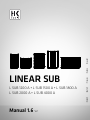 1
1
-
 2
2
-
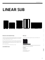 3
3
-
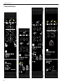 4
4
-
 5
5
-
 6
6
-
 7
7
-
 8
8
-
 9
9
-
 10
10
-
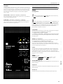 11
11
-
 12
12
-
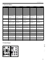 13
13
-
 14
14
-
 15
15
-
 16
16
-
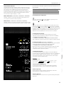 17
17
-
 18
18
-
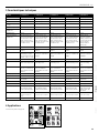 19
19
-
 20
20
-
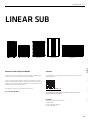 21
21
-
 22
22
-
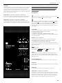 23
23
-
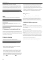 24
24
-
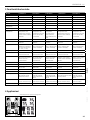 25
25
-
 26
26
-
 27
27
-
 28
28
-
 29
29
-
 30
30
-
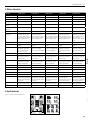 31
31
-
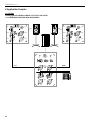 32
32
-
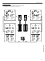 33
33
-
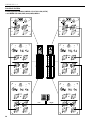 34
34
-
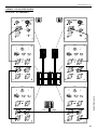 35
35
-
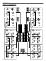 36
36
-
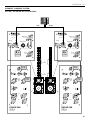 37
37
-
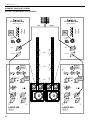 38
38
-
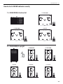 39
39
-
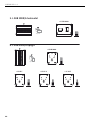 40
40
-
 41
41
-
 42
42
-
 43
43
-
 44
44
-
 45
45
-
 46
46
-
 47
47
-
 48
48


HK Audio L SUB 1200 A Manuale utente
- Categoria
- Altoparlanti della soundbar
- Tipo
- Manuale utente
- Questo manuale è adatto anche per
in altre lingue
- English: HK Audio L SUB 1200 A User manual
- français: HK Audio L SUB 1200 A Manuel utilisateur
- español: HK Audio L SUB 1200 A Manual de usuario
- Deutsch: HK Audio L SUB 1200 A Benutzerhandbuch
Documenti correlati
-
HK Audio L SUB 2000 A Manuale utente
-
-
HK Audio Linear 5 Manuale utente
-
HK Audio LINEAR 3 112 FA Manuale utente
-
HK Audio LINE BASE SINGLE Manuale utente
-
HK Audio LINEAR 5 112 XA Manuale utente
-
-
-
HK Audio E 435 INSTALL KIT Manuale utente
-
