
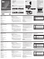
Hardware Review
A
CE604L (Local Unit) Front View
1. DVI ports
2. USB Type B Input
3. Audio Ports
4. LEDs
CE604R (Remote Unit) Front View
1. EQ Switch 1
2. DVI ports
3. EQ Switch 2
4. Wake up button
5. LEDs
CE604L (Local Unit) Rear View
1. Power Jack
2. F/W Upgrade Switch
3. RS-232 Serial Port
4. Sub / Main
CE604R (Remote Unit) Rear View
1. Power Jack
2. RS-232 Serial Port
3. Keyboard / Mouse USB
Description de l’appareil
A
CE604L (Unité locale) – Vue avant
1. Ports DVI
2. Entrée USB de type B
3. Ports audio
4. Voyants
CE604R (Unité distante) – Vue avant
1. Bouton EQ 1
2. Ports DVI
3. Bouton EQ 2
4. Bouton de réveil
5. Voyants
CE604L (Unité locale) – Vue arrière
1. Prise d’alimentation
2. Commutateur de mise à niveau du microprogramme
3. Port série RS-232
4. Secondaire/principal
CE604R (Unité distante) – Vue arrière
1. Prise d’alimentation
2. Port série RS-232
3. Clavier/souris USB
Hardwareübersicht
A
CE604L (lokales Gerät) Vorderseite
1. DVI-Anschlüsse
2. USB-Eingang, Typ B
3. Audioports
4. LED-Anzeigen
CE604R (entferntes Gerät) Vorderseite
1. EQ-Schalter 1
2. DVI-Anschlüsse
3. EQ-Schalter 2
4. Wakeup-Taste
5. LED-Anzeigen
CE604L (lokales Gerät) Rückseite
1. Stromeingangsbuchse
2. Schalter für Firmwareaktualisierung
3. Serieller RS-232-Port
4. 1./2. Signalübertragung
CE604R (entferntes Gerät) Rückseite
1. Stromeingangsbuchse
2. Serieller RS-232-Port
3. Tastatur/Maus USB
Presentación del hardware
A
CE604L (unidad local) – Vista frontal
1. Puertos DVI
2. Entrada USB de tipo B
3. Puertos de audio
4. Indicadores LED
CE604R (unidad remota) – Vista frontal
1. Conmutador EQ 1
2. Puertos DVI
3. Conmutador EQ 2
4. Botón de reanudación
5. Indicadores LED
CE604L (unidad local) – Vista posterior
1. Entrada de alimentación
2. Interruptor de actualización del rmware
3. Puerto serie RS-232
4. Sub/Principal
CE604R (unidad remota) – Vista posterior
1. Entrada de alimentación
2. Puerto serie RS-232
3. Teclado/mouse USB
Hardware
A
CE604L (unità locale) – vista anteriore
1. Porte DVI
2. Porta USB di tipo B
3. Porte audio
4. LED
CE604R (unità remota) – vista anteriore
1. Selettore EQ 1
2. Porte DVI
3. Selettore EQ 2
4. Pulsante di riattivazione
5. LED
CE604L (unità locale) – vista posteriore
1. Presa d’alimentazione
2. Interruttore aggiornamento F/W
3. Porta seriale RS-232
4. Principale/Secondaria
CE604R (unità remota) – vista posteriore
1. Presa d’alimentazione
2. Porta seriale RS-232
3. Tastiera/Mouse USB
4. Audio Ports
5. Sub / Main
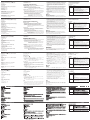
Hardware Installation
B
Rack Mounting
1. Using the screws provided in the Mounting Kit, screw the mounting
bracket into the top or bottom of the unit.
2. Screw the bracket into any convenient location on the rack.
Note: These screws are not provided. We recommend that you use M5 x
12 Phillips Type I cross, recessed type screws.
Setting Up
1. Plug the connectors on the USB DVI KVM cable set / DVI cable supplied
with this unit into the appropriate ports on the front of the Local Unit.
(CE604L).
2. Plug the connectors on the other end of the USB DVI KVM cable / DVI
cable into the appropriate ports on the local computer.
Note: If you are combining the CE604 with a KVM switch, the other end
of the USB DVI KVM cable plugs into the appropriate ports on the
KVM switch.
3. Plug a compatible monitor/display into the CE604R front panel DVI port.
Do the same or a second monitor/display.
4. Ports audio
5. Secondaire/principal
Installation du matériel
B
Montage sur bâti
1. Vissez le support de montage sur la partie supérieure ou inférieure de
l'appareil à l'aide des vis fournies dans le kit de montage.
2. Vissez le support au bâti à n’importe quel endroit vous semblant adapté.
Remarque : les vis ne sont pas fournies. Il est conseillé d'utiliser 12 vis
M5 à empreinte cruciforme Phillips de type 1.
Installation
1. Branchez les connecteurs du jeu de câbles KVM DVI USB / câble DVI
fourni avec l'appareil dans les ports correspondants situés à l'avant de
l’unité locale (CE604L).
2. Branchez les connecteurs de l'autre extrémité du jeu de câbles KVM DVI
USB / câble DVI dans les ports correspondants de l'ordinateur local.
Remarque : si vous combinez le système CE604 avec un commutateur
KVM, insérez les connecteurs de l'autre extrémité du
câble KVM DVI USB dans les ports correspondants du
commutateur KVM.
3. Branchez un moniteur/périphérique d’af chage compatible sur le port
DVI du panneau avant de l’unité CE604R. Répétez l’opération pour un
second moniteur/périphérique d’af chage.
4. Audioports
5. 1./2. Signalübertragung
Hardware installieren
B
Rack-Montage
1. Verwenden Sie die zum Montagekit gehörigen Schrauben, um den
Montagerahmen auf die Ober- bzw. Unterseite des Gerätes zu
schrauben.
2. Verschrauben Sie den Winkel mit einem freien und geeignet gelegenen
Einschub am Rack.
Hinweis: Die Schrauben sind nicht im Lieferumfang enthalten. Wir
empfehlen die Verwendung von Kreuzschlitzschrauben des
Typs M5 x 12 mit versenktem Kopf.
Einrichtung
1. Verbinden Sie die Stecker des mitgelieferten USB-DVI-KVM-Kabelsets /
DVI-Kabels mit den geeigneten Buchsen auf der Vorderseite des lokalen
Gerätes. (CE604L).
2. Verbinden Sie die Stecker am anderen Ende des USB-DVI-KVM-Kabels /
DVI-Kabels mit den betreffenden Ports des lokalen Computers.
Hinweis: Wenn Sie die CE604 mit einem KVM-Switch kombinieren
möchten, schließen Sie das andere Ende des USB-DVI-KVM-
Kabels an die entsprechenden Ports des KVM-Switches an.
4. Puertos de audio
5. Sub/Principal
Instalar el hardware
B
Montaje en rack
1. Atornille como se indica en el siguiente diagrama la escuadra de montaje
en la parte superior o inferior de la unidad con los tornillos incluidos con
el kit de montaje.
2. Atornille la escuadra en una posición deseada del rack.
Nota: los tornillos necesarios no vienen incluidos con la unidad. Le
recomendamos que utilice tornillos empotrados de estrella / cruz
M5 x 12 de tipo I.
Instalación
1. Inserte los conectores del juego de cables KVM DVI USB / cable DVI
incluido con el dispositivo en los puertos correspondientes en el panel
frontal de la unidad local. (CE604L).
2. Inserte los conectores del otro extremo del cable KVM DVI USB / cable
DVI en los puertos correspondientes de la computadora local.
Nota: si combina el CE604 con un conmutador KVM, inserte los
conectores del otro extremo del cable KVM DVI USB en los
puertos correspondientes del conmutador KVM.
4. Porte audio
5. Principale/Secondaria
Installazione dell’hardware
B
Montaggio in rack
1. Utilizzando le viti fornite con il kit di montaggio, avvitare le staffe sopra o
sotto al dispositivo.
2. Avvitare i supporti per il montaggio sul rack.
Nota: le viti per il montaggio in rack non vengono fornite. Si consiglia di
utilizzare viti a croce M5 x 12
Confi gurazione
1. Inserire i connettori del set di cavi KVM USB DVI o il cavo DVI fornito con
questa unità nelle apposite porte nella sul lato anteriore dell’unità locale.
(CE604L).
2. Inserire i connettori all’altra estremità del cavo KVM USB DVI/cavo DVI
nelle relative porte del computer locale.
Nota: se si sta abbinando il CE604 con uno switch KVM, inserire l’altra
estremità del cavo KVM USB DVI nella relativa porta dello switch.
3. Collegare un monitor o schermo compatibile alla porta DVI del pannello
anteriore del CE604R. Eseguire la stessa operazione per collegare un
secondo monitor/schermo.
4. (Optional) For control of serial devices, connect the RS-232 serial port
on the local unit to a serial port on the local computer. Connect a serial
device on the RS-232 serial port on the remote unit.
5. Plug either end of the Cat 5e cable into the CE604L's Sub / Main ports.
Plug the other end of the Cat 5e cable into the Sub / Main ports of the
Remote Unit (CE604R).
6. Plug one of the power adapters (supplied with this package) into a DC
source; plug the adapter's power cable into the CE604L's Power Jack.
7. Plug the cables from the remote console devices (mouse, keyboard,
monitor, speakers, microphone), into their ports on the Console side of
the CE604R.
8. Plug the second power adapter (supplied with this package) into a DC
source; plug the adapter's power cable into the CE604R's Power Jack.
Operation
Picture Adjustment
Use the EQ switch to adjust the equalization strength and improve an
image. There is an EQ switch that corresponds to each display connected
to the CE604R (front panel).
The values range from 0-7 where:
7: strongest equalization
0: weakest equalization
4. (Facultatif) Pour contrôler des périphériques série, reliez le port série RS-
232 de l’unité locale à un port série de l'ordinateur local. Connectez un
périphérique série au port série RS-232 de l’unité distante.
5. Branchez une extrémité du câble de catégorie 5e sur les ports Principal /
Secondaire de l’unité locale CE604L. Branchez l’autre extrémité du câble
de catégorie 5e sur les ports Principal / Secondaire de l’unité distante
(CE604R).
6. Branchez l'un des adaptateurs secteur fournis sur une prise de courant et
sur la prise d'alimentation de l'unité locale CE604L.
7. Branchez les câbles des périphériques de console distants (souris,
clavier, haut-parleurs, microphone) sur les ports correspondants de la
section de console de l’unité CE604R.
8. Branchez le deuxième adaptateur secteur fourni sur une prise de courant
et sur la prise d'alimentation de l'unité distante CE604R.
Fonctionnement
Réglage de l’image
Utilisez le bouton EQ pour régler le niveau d'égalisation et améliorer une
image. Il y a un bouton EQ qui correspond à chaque périphérique d’af chage
connecté à l’unité CE604R (panneau avant).
Les valeurs s’étendent de 0 à 7 où :
7: égalisation la plus forte
0: égalisation la plus faible
3. Schließen Sie einen kompatiblen Monitor bzw. Bildschirm an die
vorderseitige DVI-Buchse der CE604R an. Wiederholen Sie dies für den
zweiten Monitor bzw. Bildschirm.
4. (Optional) Zur Steuerung serieller Geräte verbinden Sie den seriellen RS-
232-Anschluss des lokalen Gerätes mit einem seriellen Port am lokalen
Computer. Verbinden Sie ein serielles Gerät mit dem seriellen RS-232-
Anschluss der Empfangseinheit.
5. Verbinden Sie ein Ende des Kat. 5e-Kabels mit den Anschlüssen
Main bzw. Sub der CE604L. Verbinden Sie das andere Ende des Kat.
5e-Kabels mit den Anschlüssen Main / Sub des Empfangsgerätes
(CE604R).
6. Verbinden Sie eines der mitgelieferten Netzteile mit einer Steckdose und
das Netzkabel mit der Stromeingangsbuchse der CE604L.
7. Verbinden Sie die Kabel der Konsolgeräte der Gegenstelle (Maus,
Tastatur, Lautsprecher, Mikrofon) mit den entsprechenden Buchsen im
Konsolabschnitt der CE604R.
8. Verbinden Sie das zweite mitgelieferte Netzteil mit einer Steckdose und
sein Netzkabel mit der Stromeingangsbuchse der CE604R.
Bedienung
Bild einstellen
Mit dem EQ-Schalter können Sie die Verstärkung bzw. Dämpfung justieren
und die Bildqualität optimieren. Es gibt je einen EQ-Schalter für jeden
Bildschirm, der an die Vorderseite der CE604R angeschlossen ist.
3. Enchufe un monitor o una pantalla compatible al puerto DVI situado en el
panel anterior del CE604R. Repita este procedimiento para el segundo
monitor / la segunda pantalla.
4. (Opcional) Para controlar dispositivos serie, conecte el puerto serie
RS-232 de la unidad local a un puerto serie de la computadora local.
Conecte un dispositivo serie al puerto serie RS-232 de la unidad remota.
5. Conecte un extremo del cable de Cat. 5e a los puertos Main / Sub de la
unidad local CE604L. Conecte el otro extremo del cable a los puertos
Main / Sub de la unidad remota (CE604R).
6. Conecte uno de los adaptadores de alimentación incluidos a una toma
eléctrica y el cable de alimentación del adaptador a la entrada de
alimentación de la unidad local CE604L.
7. Conecte los cables de los dispositivos de consola remotos
(mouse, teclado, altavoces y micrófono) a los puertos de consola
correspondientes de la unidad remota CE604R.
8. Conecte el segundo adaptador de alimentación incluido a una toma
eléctrica y el cable del adaptador a la entrada de alimentación de la
unidad remota CE604R.
Funcionamiento
Ajustar la imagen
Utilice el conmutador EQ para ajustar el nivel de ecualización y mejorar
la calidad de la imagen. Hay un conmutador EQ para cada una de las
pantallas conectadas a la unidad remota CE604R (panel frontal).
4. (Opzionale) Per controllare dispositivi seriali, collegare la porta seriale
RS-232 dell’unità locale a una porta seriale sul computer locale.
Collegare un dispositivo seriale alla porta seriale RS-232 sull’unità
remota.
5. Inserire un’estremità del cavo Cat.5 nella porta principale o secondaria
del CE604L. Inserire l’altra estremità del cavo Cat 5e nella porta
principale o secondaria dell’unità remota (CE604R).
6. Inserire uno degli alimentatori (in dotazione) in una presa di corrente CA,
quindi inserire il cavo dell’alimentatore nella presa d’alimentazione del
CE604L.
7. Inserire i cavi dei dispositivi dei dispositivi della console remota (mouse,
tastiera, altoparlanti, microfono) nelle rispettive porte sul lato della
console del CE604R.
8. Inserire il secondo alimentatore (in dotazione) in una presa di corrente
CA, quindi inserire il cavo dell’alimentatore nella presa d’alimentazione
del CE604R.
Funzionamento
Regolazione dell’immagine
Utilizzare il selettore EQ per regolare la potenza di equalizzazione e
migliorare un'immagine. È presente un selettore EQ per ciascuno schermo
collegato al CE604R (pannello anteriore).
I valori vanno a 0 a 7, dove:
7: equalizzazione più potente
LED Display
LED Indication
Link
(Green)
• Lights steadily to indicate that the connection to the Local / Remote
unit is ok.
• Flashes every 0.25 seconds to indicate that there is a problem on the
Cat5 Main connection.
• Fashes every 0.5 seconds to indicate that there is a problem on the
Cat5 Sub connection.
• Flashes together with the Power LED to indicate that rmware
upgrade is in progress.
Power
(Green)
• Lights steadily to indicate that the Local / Remote unit is receiving
power.
• Flashes together with the Link LED to indicate that rmware upgrade
is in progress.
Affi chage des voyants
Voyant Indication
Voyant de
liaison (vert)
(Link)
• S’allume en continu pour indiquer que la connexion à l’unité
locale/distante est correcte.
• Clignote toutes les 0,25 secondes pour signaler un problème
au niveau de la connexion principale du câble de catégorie 5.
• Clignote toutes les 0,5 secondes pour signaler un problème au
niveau de la connexion secondaire du câble de catégorie 5.
• Clignote en même temps que le voyant d’alimentation pour
indiquer que la mise à jour du microprogramme est en cours.
Voyant
d’alimentation
(vert) (Power)
• S'allume en continu pour indiquer que l'unité locale/distante est
sous tension.
• Clignote en même temps que le voyant de liaison pour indiquer
que la mise à jour du microprogramme est en cours.
Die möglichen Werte laufen von 0 bis 7, wobei gilt:
7: größte Laufzeitfehlerkorrektur
0: kleinste Laufzeitfehlerkorrektur
LED-Anzeige
LED-Anzeigen Anzeige
Verbindung
(grün)
• Leuchtet stetig, wenn die Verbindung zur Sende- bzw.
Empfangseinheit hergestellt wurde.
• Blinkt alle 0,25 Sekunden, wenn ein Problem mit der Kat.
5-Verbindung Main besteht.
• Blinkt alle 0,5 Sekunden, wenn ein Problem mit der Kat.
5-Verbindung Sub besteht.
• Blinkt zusammen mit der Betriebsanzeige, während die
Firmware aktualisiert wird.
Stromversorgung
(grün)
• Leuchtet dauerhaft, wenn die Sende- bzw. Empfangseinheit
mit Strom gespeist wird.
• Blinkt zusammen mit der Verbindungsanzeige, während die
Firmware aktualisiert wird.
El rango de valores permitidos comprende del 0 al 7, siendo:
7: mayor compensación
0: menor compensación
Indicador LED
Indicador LED Indicación
Enlace (verde) • Se ilumina cuando la conexión con la unidad local/remota
se ha establecido.
• Parpadea cada 0,25 segundos cuando existe un problema
con la conexión Main (Principal) de Cat. 5.
• Parpadea cada 0,5 segundos cuando existe un problema
con la conexión Sub de Cat. 5.
• Parpadea conjuntamente con el indicador de alimentación
cuando se está actualizando el rmware.
Alimentación
(verde)
• Se ilumina cuando la unidad local/remota está recibiendo
corriente eléctrica.
• Parpadea conjuntamente con el indicador de enlace cuando
se está actualizando el rmware.
0: equalizzazione più debole
Indicatore LED
LED Indicazione
Collegamento
(verde)
• Rimane acceso sso per indicare che il collegamento con
l’unità locale/remota funziona.
• Lampeggia ogni 0,25 secondi per indicare che c’è un
problema con il collegamento Cat5 principale.
• Lampeggia ogni 0,5 secondi per indicare che c’è un
problema con il collegamento Cat5 secondario.
• Lampeggia assieme al LED di alimentazione per indicare
che è in corso l’aggiornamento del rmware.
Alimentazione
(verde)
• Rimane acceso sso a indicare che l’unità locale/remota è
alimentata.
• Lampeggia assieme al LED di collegamento per indicare
che è in corso l’aggiornamento del rmware.
B
Package Contents
1 CE604L (Local Unit)
1 CE604R (Remote Unit)
1 USB DVI KVM Cable Set
1 DVI Cable
2 Power Adapters
1 Mounting Kit
1 User Instructions
CE604L Front View
CE604R Front View
CE604L Rear View
CE604R Rear View
Hardware Installation
© Copyright 2013 ATEN
®
International Co., Ltd.
ATEN and the ATEN logo are trademarks of ATEN International Co., Ltd. All rights reserved.
All other trademarks are the property of their respective owners.
This product is RoHS compliant.
Part No. PAPE-1223-A30G Printing Date: 06/2013
DVI Dual View KVM Extender
Quick Start Guide
CE604
CE604 DVI Dual View KVM Extender Quick Start Guide
www.aten.com
Système d’extension KVM Dual View DVI CE604 – Guide de démarrage rapide
www.aten.com
CE604 KVM-Verlängerung für DVI-Zweischirmsysteme Kurzanleitung
www.aten.com
Sistema de extensión KVM USB para dos pantallas DVI CE604 Guía rápida
www.aten.com
Estensore KVM DVI Dual View CE604 – Guida rapida
www.aten.com
Simply Better Connections
Important Notice
Considering environmental protection, ATEN
does not provide a fully printed user manual
for this product. If the information contained
in the Quick Start Guide is not enough for
you to configure and operate your product,
please visit our website www.aten.com, and
download the full user manual.
Online Registration
http://eservice.aten.com
Technical Phone Support
International:
886-2-86926959
North America:
1-888-999-ATEN Ext: 4988
United Kingdom:
44-8-4481-58923
All information, documentation, firmware,
software utilities, and speci cations contained in
this package are subject to change without prior
noti cation by the manufacturer. Please visit our
website http://www.aten.com/download/?cid=dds
for the most up-to-date versions.
The following contains information that relates
to China:
1
2
3 4
1
2
3
4
1
3
4
5
2
1
5
3 42
Local PC
USB DVI KVM cable Set
DVI cable
1
2
CE604L
Cat 5e cable
CE604L
CE604R
7
8
6
5
4
4
CE604R
3
Rack Mounting
Setting Up
A
Hardware Review
La pagina si sta caricando...
-
 1
1
-
 2
2


in altre lingue
- English: ATEN CE604 Quick start guide
- français: ATEN CE604 Guide de démarrage rapide
- español: ATEN CE604 Guía de inicio rápido
- Deutsch: ATEN CE604 Schnellstartanleitung
- русский: ATEN CE604 Инструкция по началу работы
- português: ATEN CE604 Guia rápido
- 日本語: ATEN CE604 クイックスタートガイド