
www.amcelettronica.com
SR136 V1.2.1 IT-EN
SR136
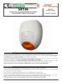
DISPOSITIVO DI SEGNALAZIONE DA ESTERNO
SELF-POWERED SIREN FOR EXTERNAL
MANUALE
DI INSTALLAZIONE
TECHNICAL MANUAL
COMPLIANT
CEI EN 50131-4:2010-08
SR136 è un dispositivo di segnalazione per esterno autoalimentata che risponde alle diverse esigenze di installazione.
Oltre alla possibilità di selezionare diverse sonorità e modalità di attivazione, SR136 è in grado di segnalare lo stato impianto
inserito/disinserito, la memoria di allarme, le anomalie all’alimentazione.
Tutte le funzioni sono gestite da microcontrollore, pertanto la programmazione è facile ed intuitiva. Tutte le funzioni sono selezionabili
attraverso dei DIP-SWITCH. (ci sono 2 gruppi di dip-switch, MODE e FUNCTIONS)
Il dispositivo è protetto contro le attivazioni accidentali, infatti ogni volta che viene modificata la configurazione emette un suono
che avverte che il sistema è pronto. Nel caso di configurazione a 2 fili è necessario dare la tensione di lancio 2 volte.
N.B. fare attenzione al suono di conferma configurazione, che viene emesso dall’altoparlante.
DESCRIZIONE
SR136 is a self-powered signaling device for external that meets the various installation requirements.
Besides the possibility to select different sounds and activation ways, SR136 is able to report the system status ( armed / disarmed
), the alarm memory, the power anomalies.
All siren functions are handled by the microcontroller, so the programming is easy and intuitive.
All functions are selectable via DIP-SWITCH ( there are 2 sets of dip switches, MODE and FUNCTIONS ).
The siren is protected against accidental activation, in fact every time you change the configuration the siren emits a sound indica-
ting that the system is ready. In the case of 2-wires configuration is necessary to give 2 times the launch voltage.
NOTE: pay attention to the setup confirmation sound, which is emitted from the speaker.
DESCRIPTION

www.amcelettronica.com
SR136 V1.2.1 IT-EN
SR136 dispone dei seguenti modi di attivazione:
SR136 has the following modes of activation:
- Comando di start: MORSETTO S
- Start trigger: S TERMINAL
dip 1 OFF positivo a mancare
positive missing
dip 1 ON negativo a mancare
negative missing
- Comando di stato impianto INSERITO: MORSETTO A
- System status trigger ARMED: A TERMINAL
dip2 OFF morsetto A con negativo
trigger on A terminal with Negative
dip 2 ON morsetto A con positivo
trigger on A terminal with Positive
- Comandi separati lampada e altoparlante:
- Lamp and speaker separated triggers:
dip 3 OFF: comando unico (suono e lampada su morsetto S)
unique trigger ( speaker and lamp on S terminal )
dip 3 ON : suono su A e lampada su S
speaker on A terminal and lamp on S terminal
- Funzionamento a 2 fili:
- 2 wires function:
dip 4 OFF tradizionale (2 fili di alimentazione, 1 filo comando allarme)
traditional ( 2 power supply wires, 1 wire for alarm trigger )
dip 4 ON 2 fili di alimentazione con partenza immediata
2 power supply wires with starting immediately
ELENCO MODI ATTIVAZIONE (DIP MODE) - LIST OF ACTIVATION MODES (DIP MODE)
nota 1: la polarità per i comandi separati è sempre controllata dal dip 1 e dip 2
nota 2: la partenza con il funzionamento a 2 fili avviene dopo la seconda attivazione
NOTA 3 : programmando il funzionamento a 2 fili (dip 4 ON) si perde la conformità alla norma CEI EN 50131-
4:2010-8 e pertanto la marchiatura IMQ.
note 1: the polarity for separated triggers is always controlled by dip 1 and dip 2
note 2: the starting of 2-wires function takes place after the second activation
note 3: programming 2-wires operation (dip 4 ON) is lost compliance with CEI-EN 50131-4: 2010-8 and there-
fore IMQ marking
ASSEMBLAGGIO = VEDI ULTIMA PAGINA ASSEMBLY = SEE LAST PAGE

www.amcelettronica.com
SR136 V1.2.1 IT-EN
ELENCO FUNZIONI (DIP FUNCTIONS) - FUNCTIONS LIST ( DIP FUNCTIONS )
SR136 dispone delle seguenti funzioni, attivabili SINGOLARMENTE PORTANDO IN ON il dip corrispondente:
SR136 has the following functions that can be activated INDIVIDUALLY BRINGING ON the corresponding dip:
- Memoria di allarme sonora (DIP 1 ON):
- Sound alarm memory ( DIP 1 ON ):
emette una melodia quando si disinserisce l’impianto dopo un allarme
a melody sounds when you switch off the system after an alarm
- Memoria di allarme visiva (DIP 2 ON):
- Visual alarm memory ( DIP 2 ON ):
flash veloci continui dopo un allarme ad impianto inserito (si spegne quando viene disinserito l’impianto)
continue fast flashes after an alarm when the system is armed ( it turn off when the system is disarmed)
- Segnalazione stato impianto INSERITO/DISINSERITO di tipo sonora (DIP 3 ON):
- Sound system status indication ARMED / DISARMED ( DIP 3 ON ):
emette 3 BIP quando si inserisce l’impianto, 1 bip lungo quando si disinserisce l’impianto
it emits 3 beep when you arm the system, 1 long beep when you disarm the system
- Segnalazione stato impianto INSERITO/DISINSERITO di tipo visiva (DIP 4 ON):
- Visual system status indication ARMED / DISARMED (DIP 4 ON):
emette 3 brevi flash quando si inserisce l’impianto, 1 flash lungo quando si disinserisce l’impianto
it emits 3 flashes when you arm the system, 1 long flash when you disarm the system
- Segnalazione fissa di impianto INSERITO (DIP 5 ON):
- Fixed signaling of system ARMED ( DIP 5 ON ):
quando l’impianto è inserito emette un doppio lampeggio
when the system is armed gives a double flash
- Segnalazione di dispositivo OK “stand by” (DIP 6 ON):
- Siren OK indication “ stand by “ ( DIP 6 ON ):
emette un breve flash ogni 10 sec. quando il dispositivo sta funzionando correttamente
it emits a short flash every 10 seconds when the siren is operating properly
- Modifica tipo di Tono sonoro (DIP 7 ON):
- Change type sound ( DIP 7 ON ): loss of Omologation
Cambia il tipo di suono (da 1400Hz/1700Hz a 1600Hz/3500Hz)
Change the type of sound ( from 1400Hz/1700Hz to 1600Hz/3500Hz)
- Temporizzazione (DIP 8 ON):
- Timing of the siren ( DIP 8 ON ):
Aumenta la durata max del suono del dispositivo senza controllo della centrale, da 3’ a 15’
Increases the maximum duration of the siren sound without system control from 3’ to 15’

www.amcelettronica.com
SR136 V1.2.1 IT-EN
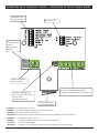
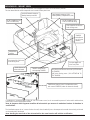
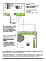
DESCRIZIONE DELLA SCHEDA ELETTRONICA - DESCRIPTION OF THE ELECTRONIC BOARD
funzioni dip-swicth
dip-switch funcions
dip-switch mode
terminali batteria
tampone
backup battery
terminals
terminali altoparlante
speaker terminals
connettore lampeggiatore
(posto sul tappo antischiuma)
lamp connector
( on the antifoam cap )
TAMPER antiapertura
Anti-opening TAMPER
morsetti di collegamento alla centrale
terminals for the connection to the control unit
--terminali + - = alimentazione (13.8Vcc)
-- TAMPER = terminali di collegamento alla linea tamper della centrale
-- terminale S = comando attivazione dispositivo
-- terminale A = comando stato impianto centrale (serve per avere le segnalazioni sonore e/o luminose)
-- terminals + - = siren power supply ( 13.8Vcc )
-- TAMPER = terminals for the connection to the control unit tamper line
-- terminal S = siren activation trigger
-- terminal A = control unit status trigger ( need to get the sounding and / or bright signalling )

www.amcelettronica.com
SR136 V1.2.1 IT-EN
MONTAGGIO - MOUNT SIREN
L’installazione a norma prevede l’utilizzo di una vite fissata a muro, la cui testa andrà a premere il microswitch antirimozione,
posizionato sul lato inferiore della scheda.
Nota: la piegatura della linguetta metallica del microswitch per ottenere la medesima funzione fa decadere la
certificazione.
The installation expect the of a screw fixed to the wall, whose head will press the tamper anti-removal microswitch, positioned
on the underside of the board.
Note: bending the metal tab of the microswitch for the same function will void the certification.
- vano batteria tampone (2Ah)
- backup battery compartment (2Ah)
altoparlante
speaker
fori di fissaggio a muro
holes for wall fixing
- fori di fissaggio a muro
- holes for the wall fixing
- foro passaggio cavi
- wires entry hole
foro coperchio di chiusura
hole closing cover
- foro coperchio di chiusura
- hole closing cover
bussola vite di chiusura cover ABS (ATTENZIONE
AL TAMPER)
ABS cover closing screw ( PAY ATTENTION TO
THE TAMPER)
TAMPER antiapertura
anti-opening TAMPER
scheda elettronica
electronic board
TAMPER antistrappo (sotto la scheda elettronica)
anti-removal TAMPER (under the electronic board)
La scheda del dispositivo e gli altri componenti sono alloggiati all’interno di una cassetta in plastica:
The siren board and the other components are housed inside a plastic box:
- terminali batteria tampone
- backup battery terminals
- TAMPER
antischiuma
- a n t i f o a m
TAMPER

www.amcelettronica.com
SR136 V1.2.1 IT-EN
Nota: Per ottenere tutte le visualizzazioni di stato centrale, (inserito/disinserito, memoria allarme ecc.) è neces-
sario che il dispositivo abbia collegato l’alimentazione (+ -). Quando viene a mancare l’alimentazione (funziona-
mento solo in batteria) non saranno attivate tali segnalazioni per una questione di ottimizzazione dei consumi.
Mentre il lampeggio in caso di allarme è sempre garantito.
Note: In order to obtain all the information of status (panel armed/disarmed, alarm memory, ...), the device must
have linked the supply terminals (+ - ). When the supply is missing (the siren works only with battery), the signal-
ling will be not active for otpimization of consumptions, while the flashing for the alarm is always on.

7
www.amcelettronica.com
SR136 V1.2.1 IT-EN
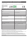
SPECIFICHE TECNICHE - TECHNICAL SPECIFICATION
Alimentazione: l’apparecchiatura deve essere alimentata da un circuito SELV
(CEI EN 60950-1)
Power supply: the equipment must be powered by a SELV cicuit (CEI EN
60950-1)
13,8Vcc nominali (min 11V; max 15V)
13,8Vcc rated (min 11V; max 15V)
Corrente massima - Maximal current 1.4 A in allarme - 0.06 A a riposo
1.4 A in alarm - 0.06 A at rest
Tensione minima di comando (positivo a mancare)
Minimum trigger voltage ( positive missing )
6Vcc
Frequenza fondamentale - Fundamental frequency 1400Hz/1700Hz
Frequenza secondaria - Secondary frequency 1600Hz/3500Hz
Pressione sonora senza kit antischiuma
Sound pressure whitout Antifoam Kit
Tono1 DIP7 OFF: livello minimo 103 dB(A) a 1mt - 85 db(A) a 3mt
Tono2 DIP7 ON :livello minimo 102 dB(A) a 1mt - 84 db(A) a 3mt
Tone1 DIP7 OFF : minimum level 103 dB(A) at 1mt - 85 db(A) a 3mt
Tone2 DIP7 ON : minimum level 102 dB(A) at 1mt - 84 db(A) a 3mt
Pressione sonora con kit antischiuma K-136
Sound pressure whit Antifoam Kit
Tono1 DIP7 OFF : livello minimo 100 dB(A) a 1mt - 83 db(A) a 3mt
Tono2 DIP7 ON : livello minimo 103 dB(A) a 1mt - 82 db(A) a 3mt
Tone1 DIP7 OFF : minimum level 100 dB(A) a 1mt - 83 db(A) a 3mt
Tone2 DIP7 ON : minimum level 103 dB(A) a 1mt - 82 db(A) a 3mt
Durata max suono - Maximal sound period 15’
Grado IP - IP grade IP34 (IMQ) - IP54 (PRIMA Ricerca & Sviluppo)
Temperature di esercizio - Operative temperature range da -25°C a +55°C
from -25°C to +55°C
Batteria tampone - Backup battery 12V 2.2Ah
Antiapertura - Anti opening •
Cover - Housing - Boiter acciao / ABS - steel / ABS
Dimensioni - Dimensions l=220 mm h=280 mm p=100mm
L’installazione deve essere eseguita a regola d’arte da personale specializzato.
Il Produttore declina ogni responsabilità nel caso in cui il prodotto venga manomesso da persone non autorizzate.
Si raccomanda di verificare il corretto funzionamento del sistema d’allarme almeno una volta al mese. Un sistema di allarme elettronico
affidabile non evita intrusioni, rapine, incendi o altro, ma si limita a diminuire il rischio che tali situazioni si verifichino.
Installation must be carried out following the local installation norms by qualified personnel
AMC Elettronica S.r.l. refuses any responsibility when changes or unauthorized repairs are made to the product/system.
It is recommended to test the operation of the alarm product/system at least once a month. Despite frequent testing and due to, but
not limited to, any or all of the following: tampering, electrical or communication disruption or improper use, it is possible for the
product/system to fail to prevent burglary, robbery, fire or otherwise. A properly installed and maintained alarm system can only reduce
the risk that this happens.
Meets the requirements:
Conforme ai requisiti:
CEI EN 50131-4:2010-08
Grade 2
Class 4
MONTAGGIO VERSIONE ANTISCHIUMA - MOUNTIN ANTIFOAM VERSION
Per modificare la sirena e portarla in versione Antischiuma, montare lo specifico Kit K-136, facendo riferimento alle istruzioni di
montaggio ad esso allegate.
To change the siren to antifoam version, mount the specific Kit K-136, and referring to the instruction attached to it.

8
www.amcelettronica.com
SR136 V1.2.1 IT-EN
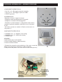
PROCEDURA ASSEMBLAGGIO - ASSEMBLY PROCEDURE
COMPONENTI SIRENE SR136
- 2 viti 3.5 x 13 – Bloccaggio coperchio metallico
- 1 vite 3.9 x 22 – bloccaggio coperchio in ABS
- 2 TAPPI in gomma
ASSEMBLAGGIO
- Montare sul fondo i 2 tappi di chiusura
- Collegare cavetti dell’Altoparlante. No polarità
- Collegare il connettore del lampeggiatore
- Terminato il posizionamento e collegamento della sirena
montare il coperchio metallico e bloccarlo con le 2 viti (punti
A e B)
- Per ultimo montare la calotta in Plastica e bloccarla con
vite (punto C)
COMPONENTS SIREN SR136
- 2 SCREWS 3.5 x 13 – Metallic cover locking
- 1 SCREWS 3.9 x 22 – ABS cover locking
- 2 Rubber plugs
ASSEMBLY
- Install rubber plugs on the bottom
- Connect cables speaker. Without polarity
- Connect connector flasher
- Finished the connection and positioning of the siren, mount the
metal cover and secure it with the 2 screws (A and B)
- Finally mount the plastic cover and secure it with screw (point C)
-
 1
1
-
 2
2
-
 3
3
-
 4
4
-
 5
5
-
 6
6
-
 7
7
-
 8
8


in altre lingue
- English: AMC SR136
Documenti correlati
Altri documenti
-
 Lince OBLO'/E Istruzioni per l'uso
-
 Lince 1964-SAXA-A Istruzioni per l'uso
-
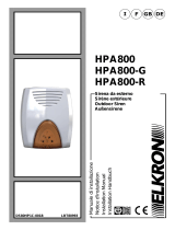 Elkron HPA800 Guida d'installazione
-
 Lince 1943-ONDA4-A Istruzioni per l'uso
-
Risco ProSound Installation & Programming Manual
-
 RISCO Group ProSound Installation & Programming Manual
-
ADEMCO Security System VISTA-15CN Guida d'installazione
-
Crow RUNNER 8/64 Guida d'installazione
-
-
 Lince 9518-GOLD-OBLO/L Istruzioni per l'uso


