
SECTION 1
SEFIVICE
MANUAL
TABLE OF
CONTENTS
I.
TECHNICAL DATA
.... .. ........ 2,
II.
DISMANTLING OF UNIT
.. ., ,..... 4
ÍII.
CONTROLS
.......... 5
IV.
PRINCIPAL PÁRTS IOCATIONS
............... 5
V. VÀRACTOR TUNER
AND PRESET TUNING
SYSTEM....
............,.,.
6
l.
VARACTOR TUNER
. .
. . .
.
.
.
.............ó
2.
PRESET
TUNING SYSTEM
. . , . ,.-.,..,.,.-,9
VI.
TUNER ADJUSTMENT
............I0
I. FM
SECTION ADJUSTMENT
.
. . .,........I0
2. LW SECTION ADJUSTMENT
. . ,.,.,,..,12
3. MW SECTION
ADJUSTMENT
.
. . ..........I3
VII. MAIN AMP ADJUSTMENT
,... . , . , . , , . , . . . . . . . 14
VIII. TUNING
CORD THREADING
.. . , . , . , . . . . . . . . . . I5
IX. CLASSIFICATION
OF
VARÍOUS
P.C BOARD
.
.
.
.
. . . . .......16
I. RELATION OF P,C BOARD
TITLE AND
IDENT]FICATION
NUMBER . . . , , . , . , . , , , , . , . I ó
2. COMPOSITION
OF
VARIOUS
P.CBOARD ...... _........ _17
FoÍ baÍc
adjusimênrs, ne.suring nerhoG,
6d
operari.g
prin.iptes,
reter to CENEÍ|ÀL OPERÁTING PRINCIPLES AND
ADJUSTMENTS.

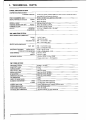
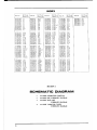
I. TECHNICAL
DATA
PoWER AMPLIFIER
SECTION
CONTINUOUS
POWER OUTPUT
2{HÁNNELS DRIVEN
14 Watts
per
chdnel, nininun RMS, at 8 ohms
from 40 to 20,000 Hzwilh
no
more
thm
0-8%
lotal tamonic distoilio..
POWER BANDWIDTH
OHF)
SIGNAL
TO NOISE RATIO
OHF)
RESIDUÀLNOISE
CHÀNNEL SEPÀRATION íHF)
l5 Hz to40
tHzl8 ohns. dislortion withiÍ 0.8%
PHONO
AUX
SPEAKERS
HEADPHONE
PHONO Betler
rhan50 dB at 1,000 Hz
Les rhán 0.8
nV
al
8 onns
More than
30
(l
kHz.8 ohmt
A,
B
(4
to
16 ohmt/Á+B
(8
ro 16 ohm9
PIN: 150 nV/100
k óhns
DIN:
l0 nv/180
k ohms
PIN:150óV/l00kohns
DIN:
150
mv/r00 k ohms
30
Hz lo
15
kgz
ll
dB
l0 Hz lo ?0 kHz
+0
dB, 2
dB
+10
dB at 100 Hz,
+5
dB
at
10 kHz
(Volume
conbol setal
-30d8
position)
INPUT SENSIÏVITY/IMPEDANCE
PHONO
AUX
TAPE MONITOR
DAMPINC FACTOR
ottrPuT
PRE ÁMPLIFIER SECTION
OTITPUT I'EVEL/IMPEDANCE
TONE CONTROL
LOT'DNESS CINTROL
FREQUENCY
RANCE
SENSITIVITY
OHF)
CAPTURE
RATIO
SELECTIVITY
(IHF)
IMÀGE
REJECTION
IF RE.'ECTION
SPURIOUS REJECTION
AM STJPPRESSION
SIGNAL
TO NOISE RATIO
HÁRMONIC
DISTORTION
TT'NING
INDICATOR
STEREO
SEPARATION
SUBCARRIER
SUPPRESSION
ANTENNA INPUT
IMPEDANCE
88
MHz ro
108
MHz
1.5 dB
TAPE REC
FREQT'ENCY
RESPONSE
PIIONO
(RIAA)
TUNER/AUX/'TAPE
MONITOR
BASS
TREBLE
More rhan 5t
dB
(98
MHz)
More than 70
dB
(98
MÈz)
Móre than ?0 dB
(98
MHz)
50
dB
60dB
MONO
STEREO
Le$ thàn 0,3%
i
100%
nodtlation)
Les ihan 0,6%
(1009',
modulÁ1ion)
C€nter Turiq meter
a F
More than 40 dB
(l
tHz)
300 ohns
balanced, ?5 ohms unbabnced
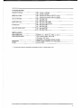
FM TUNER SECTTON

AM TUNER
SECTION
FREQUENCY RANGE
SENSITIVITY
(IHF)
SELECTIVITY
OHF)
SICNAL TO NOISE RATIO
IMAGE REJECTION
IF REJECTION
SEMI{ONDUCTORS
POWER
REQUIRDMENTS
DIMENSIONS
520 kHz
10 1,605 kgz
150 kHz
to 350 kHz'
200
Àrv/n
(tEr
anl€nna) 20liv
(ext.
antêntu)
300
lrv/h
(bar
antenna)
30llv
{ext.
antÈnM)
MW: More
than 30 dB
LW: More
than 30 tlB
More than
55 dB
(l
MHz)
More tho
35 dB
(240
ktlz)
MW:
Moie than 45 dB,
Lwr
More thd 50dB
TÍaÍníors:
27, Diodes: 25, FET!:
2,
CSÁ, ULa.d
LA hodelsr l20V,60Hz
CEE nodeh: 220V, 50 Hz
Olher nodels: 110/220l240V,
50/60 Hz swilchable
440(w) x
l2s(H) x 26s(D)nm
(17.3
x 4.9 x
r0.4")
WETGHT
6.2
ke
(l
I
T
lbt
'
Forimprovem€nl purposes,
specilications and d€sisn are
snbj.ct tóchanse{nhost nolic€,

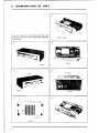
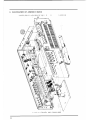
DISMANTLING OF
UNIT
In case of
lrouble, e1c. necessilaring disassembly.
pleáse
disassemble
in the order show.
in pholos.aphs. Reassemble
scREws
scREws
..
-: .
|
======
al
=ilÊEEë l
a
iË.-iÊE=E
.-.-.al
"t

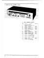
III.
CONTROLS
-n
r=
FIl
VOLI]ME
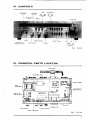
IV. PRINCIPAL
PARTS
LOCATION
Fis. 1 Controls
[.lr "t4
.-l
f.
r--Eï
lÊ.' I
l9g!)
**.""
E
nn
6U
Fig.2
Top View

V,R PC
EOARD
aÁ-5t57
IC FC EOARD
AÁ-5r56
TOUC|I
SW|ÍCH
PC BOARo ÁA-5r58
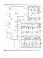
Fig.6 Block Dias.am
t:
L
t--
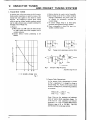
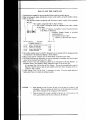
3) Acrual
Operation
Fig. 5 is a cÍcuit diagram of the high
fr€qu€ncy
amplifier stase only
of a circuit which is actually
used. Condenser
Cl and varactor diode Dl in
the diagram are equivalent to the variable
con,
denser of
an
ordinary
FM fÍont end. As can be
understood
from Fig. 3, Dl varies the capacitance
in a 4 to 16 PF ranSe
by means oí inverse bias
voltage.
This capacitance and condenser
Cl
combined caFcitance forÍns the Íesonance
circuit
with coil LA. Consequently, it is satisfactory
if
at
low.esonance
íÍ€quency, the voltage
supplied
to the varactoÍ diode d€clines,
and at hid re-
sonanc€ frequency, the voltage
supplied to th€
varactor
diod€ increas€s.
This
voltage
variation
method with variabl€ resistor, êtc.,
op€rates
in
the
sam€ way as a regulaÍ variable
cordenser.
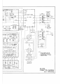
FiE.7
This
method uses a local
oscillator circuit
and
frequency mixer
circuit, and
bias voltage is
applied
to the varactor diode
for starioo
selection and is
called a
varactor
tuneÍ. Pleas€ r€fer
to the scheÍ,a-
tic diagran
foi
actuai
circuit drawing.
II
V

\/. \'ARACTOR
TUNER
AND PRESET TUNING SYSTEM
I. VARACTOR
TUNER
A
varactor tuner is th€ luner system
in
which
varáctor
diode
junction
capacitance is varied by means of the
inverse bias value applied to the
diode for station
selection.
By employing a varactor
diode.
tuning
which is same a! ordinary vaÍiable condenseÍ s),stem
cán bê mad€
without using a variable condenser by
changing control
voltage only.
l)
Features
a)
When used in an FM tuner, th€
front
end can
be
made small€r than \{hen compaÍed with a
variable condenser.
b) Station
selector butaon
positioning
is not
limited.
c) Slation sel€ction by remote control is possible.
d) Ideal voltage can be set for a certain reception
frequency beforehand, and preset
tuning can
b€
efect€d by successively
switching
the
e) If control voltsg€ sweep is at ideal speed,
automatic tuning (seàÍch tuning) is
posible-
0
Pow€r consumption
is about
the
same
as
a
variable condenseÍ system.
ï
f,
g
q
Fig. 3
Fig. 4
Tuning circuit employing a vaÍactor diode
Fig. 5 Example ofHigh Frequency
Amplifier Stage
Cncuit
+
INVERSE VOLTÀCE
2)
VaÍactor
Diode
Characteristics
As foÍ varactor
diode characteristics,
as
shown
in Frg. 3, cápacitance c
r(
changed by chm8e
in
inverse voltage
VR. Further,
ifthis varactor
diode
is used
jn
a tuning circuit,
the
following conditions
Cmax
+
CD
Cmin
+
CD
Cmai, Cmin
arc th€
maximum and
minimum
values of varactor
diode
capacitánce
change.
CD
is the
sum of stray
capacitance
and trinmer
capacitance.
K is over
l_5
b€cause FM broadcast
frequency
range is 88
to t08
MHa Fig.s 4(a)
and
4(b) show the
actual usage
method.
I

iti!È!
ruMre
\.
tti i
'iil
tI
tri
Fig. 8
lcr
lJPclo09c
TERMTNAL@@@@
TO VÀRIABLE CAPACITOR
Fig.
9

2. PRESET
TUNING
SYSTEM
l) Preset
Station
Selecrion
For preset
íatio.
selection,
there is a
mechanical
and an eleclrical
merhod.
These
are memory
equipme.t
and seiection
equipment
enabling
desÍed station
s€lection
beforehand
and selecting
thes€ pre-set
srations
by simply
d€pressing
the
respective
switches.
An ordinary
car redio,
etc. utilizes
a mechanical
station selection
system
wherein
mechanical
variation
is by
mea.s
of
a variable
condenser or
posilioning
ofa
dust corc inside
a coil.
Model
AA,1010L utilizes
an
electrical srálion
selection
system and
employs
the
varacror
tuner
explained in
a
previous
item.
2) An example
of a stllion
selection
system employ"
ing
a
varactor
tuner is
shown in Fig.
6. For skrion
selection, push
switches
are used for
s€lecuon
of voltage supply
to
the varactor
tun€r. However,
in
the
AA.10I0L, these station selection push
switches
are
puÍe
electronic system sensi.touch
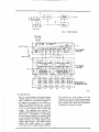
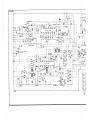
3)
Sensi-touch
Employed
Preset Station
Selection
System Operation
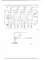
The
circult shown
in
Fig.
7 is th€
conlrol voltage
genêratinS
pres€l
volume
and sensi-touch
circuir.
Fig. 8
sho'rrs the inside
of circuit sensi-touch
IC
FPCI009C
which
include the 4 channel
circuitry.
Terminals 14 thÍou8h 17
are the input teminals;
.erminals
@, @,
@,-a
@
arêthestation
selection output
terminals; and
terminals
O ,
@
,
@
,
and
O
are rhe pilot
outpul terminals.
When
channêl I sensor
electrode is louched,
voltage
is snpplied to
the IC as rhe input signal
through
fmger (body)
resistance at t€rminal
@
.
Then,
the impedance
is lowered
at IC station
selector output
terminal
@
and
current flows
ai
shown
by
the
arrow marks in Fig.
9. Consequ-
enlly, because
the supply voltage
10 the varactor
runer
diode is changed
by the dividing ratio
of
Rb and Rc, station selection
is
possible
by
m€ans
of setting the
pr€set
volumes
beforehand
accoÍdrng
to the deriÍed broadcarl
tÍequen.res.

t
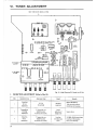
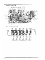
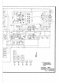
VI-
TUNER ADJUSTMENT
IIIJLTI FUNCTIOI{ PC BOARD AA-5I59À
"@
@
@
ËE
@aD
o
@.
@.
o.
FM IUNING METER ÀOJ
(LO*ER
CORE)
FM OISTORTION
ÁDJ
(I]PPEN
CONEI
aà.
o;
K-l
t:J
rkHÍr I E
i"t
rca
@.
@"TP
.o
FREOUENCY ÀOJ
i:ió'"
Á0
€Íol
H:
tr
ó",,1"R?".1-,
7{A^
\<9r
p"@.@
"op
@
@ @*@oo
ro rà aà(à
@o@
(s)
àE
È 5 .À,.À.n
aË
Fic.
l0 Multi Function P.C Board AÀ-51594
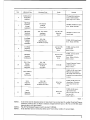
1. FM SECTION ADJUSTMENT
(RefeÍ
to Fig.
l0)
IF
Coil
IF Cóil
Tune oÍly noise withour
inlerfereÍce of hroadcasls.
2
3
108 MHz,ó0 dB
(mono)
input,
Lers than 0.3% distoition
t0

I f Tunins M€ler iÍdicalion
is nol al
@ler
posilion,
rep€tl íeps 2
a.d 3
above.
108 MHz,60 dB(moÍo) input.
EÍor: within
!250
kgz.
108 MHz, L6s than l2 dB
vR3,5 tB
88 MHz,
ó0
dB
(nono)
inpul.
Eror:
WÍhin
1250
kHz.
8
88 Mttz, Les ihan 12dB
9
98 MHz. Less than 12 dB
EÍor: Within
1250
kHz.
l0
vRl,I
kB
19.00 kHz
Connect Frequency Counter
ll
98 MHz.60 dB
Gt€reó)
input.
When ihe Í€r€o i.dicator
ràils
to light, this mans
thal
broadcast n nol beins
Íeceiv€d
t2
vR2, I
kB
40 dB
98 MHz,60 dB
G1€r€o)
l€ft
channel
inpul. Distortion
Faclor
ruí be less than
0.6%.
tl
40 dB
98 MHz,60
dB
Glereo)
Distortion
factor
musl
be
NOTE
I.
NOTE
2.
NOTE
3.
Chart I
ln the event that
the distortion facrors in
Steps 8 and 9 are not tess
than 3%, re-adjust FroÍt
End TrimÍn€.
Condensers
TCR.nd TCA to obtain a
miniÍnum average dislortion
factor at 88,98, and
108 MHz
(san€
distortion factor at all
thÍee
Doints).
PLL IC Free Running
Frequenry Ínust be an exact
19.00 kHz.
Ifthe distortion factor
is not less than
0.ó%, tuÍn IF Coil in
Step I wjthin 1/2 turn rnd adjusr.

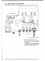
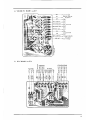
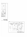
VII-
MAIN AMP
ADJUSTMENT
i-*i i-*i
'ÍxI'
'[[r
o
.@
.(a
7
Á@
.@
"@
-CF+
:C.o3 @
mQ
€
?l I
"ll
pp
/z=\
n.=
_
En!
*
((
","
))
=*H@
v
m
P{JSH swrrcH Pr soaRD aÀ-5l55
@. Ul
Fig. 12 Main
Anp P.C BoaÍd AA'5106
ldling Cuíent
Adjultment
(RefeÍ
to Fig. l2)
l Remove
Power Fuses
F2 2A
(left
channel)
and F3
2A
Gight
channel) and
connect an aÍuneter
to
2. At
non.signal input,
adj$t
Senifixed
Resiston
VR4 3008
o€ft
channel) aíd
VR4b 3008
(Íieht
channel) to
obtain a 20 mA idling
cuÍÍent.

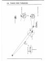
VIII.
TUNING
GORD
THRTADING
!Es
XE;
:EE
F
€
ë
t
g
z
15

I
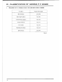
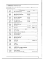
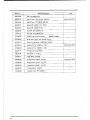
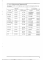
IX. CLASSIFICATION
OF
VARIOUS P.C BOARD
I.
RELATION
OF
P.C
BOARD TITLE AND
IDENTIFICATION NUMBER
P.C
Board Number
ofP.C
Board
MFC P.C Board À4.5159À
Main Amp
P.C
Board AA-5106
Touch Switch
P.C
Board AA 5158
Volume P.C
Board AA-5157
IC P.C
Board
AÁ.5156
Push Switch P.C BoaÍd AA-5155
LED P.C Board AA-5159C
Chart 4

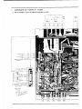
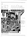
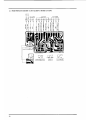
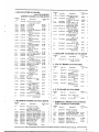
2. COMPOSITION
OF
VARIOUS
P.C
BOARD
I) MFC
P.C BOARD
AA.5I59A
&
JUMPER
P.C BOARD
AA.5'59B
."
.'"
t-
^"
r
1.1o.)
t
-r,_-
!Á so&O
j!
É
-l
ct
i
+e*.sïi6i:ï
^
*!_1o-
M
5É?(9-
-

rtr"-.r-,,oï
I
Ln-
6).
ÀÁ
-
5,6r
4,
G).
:
or
@
@
Fnn

2) ItÀrN
AMPP.C EOARD
AAslOó
@09e@9
I
I
3i TOUCH SWITCH
P,C BOARD
AA.5I58

,1)
VOLUME P.C
BOARD
AA-5t57
5) IC P.C BOARD
AA.5156
aa-5158
an-s
os@
METER{+)
I
ESET
ÍUN ING
l^^.,,"
l
@
@
@
o
@
@
na
srss
@
;
o@@@
ÁEfrqB
@áÍáá
ÁÀ-5158
o@@e@@
qqqq'rq
l9

ó)
PUSH SWITCH P,C BOARD
AA-5I55 & LED
P,C BOARD AA-5T59C
9P
d
I
Áa-to6Á
t-, t-f t7
\l
aa-srosn@
Ë
urr
ItopE I
o@9@@@o@oo
U
E
E
EI
)o

,l
t,
lt
t.'::
()rJo'Is
(s6sls-rív)
oxvo{ J d uadnnf)
I€:"
t"
t€"
" "
xJo]s
(v6tÍs-w)
cuvos J d NotIJNru tfiru{
.G":"'''''
' 'Jsn
sf,uvd auvds
g:IqNennoJÍru
,.ó1II{!IJ.I{O)
dO
gltrVI
I
IEil'r SItlVGl
z t{olrtas
-
La pagina si sta caricando...
La pagina si sta caricando...
La pagina si sta caricando...
La pagina si sta caricando...
La pagina si sta caricando...
La pagina si sta caricando...
La pagina si sta caricando...
La pagina si sta caricando...
La pagina si sta caricando...
La pagina si sta caricando...
La pagina si sta caricando...
La pagina si sta caricando...
La pagina si sta caricando...
La pagina si sta caricando...
La pagina si sta caricando...
-
 1
1
-
 2
2
-
 3
3
-
 4
4
-
 5
5
-
 6
6
-
 7
7
-
 8
8
-
 9
9
-
 10
10
-
 11
11
-
 12
12
-
 13
13
-
 14
14
-
 15
15
-
 16
16
-
 17
17
-
 18
18
-
 19
19
-
 20
20
-
 21
21
-
 22
22
-
 23
23
-
 24
24
-
 25
25
-
 26
26
-
 27
27
-
 28
28
-
 29
29
-
 30
30
-
 31
31
-
 32
32
-
 33
33
-
 34
34
-
 35
35


in altre lingue
- English: Akai AA-1010 User manual
Altri documenti
-
Eaton EASY806-DC-SWD Istruzioni per l'uso
-
Gendex GXS-700 Manuale utente
-
Raymarine Ray 201 Manuale utente
-
Technics SA-GX530 Manuale utente
-
Pioneer SX-535 Manuale utente
-
Realistic DX-300 Manuale utente
-
Crown EQ-2 Manuale del proprietario
-
Yamaha R-700 Manuale del proprietario
-
-
Philips RC4720/01 Product Datasheet