

5-Channel Audio Mixer
Please read these op erating instr uctions caref ully prior to operation and keep them for later refe rence.
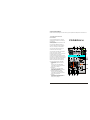
1 Operating Elements and
Connections
1 Mono input MIC IN (bal.) to connect a
mic r ophone to c h annel CH 1 via XLR plug
or 6.3mm plug
At th e XLR jack, a phantom power of +18 V
is al ways presen t.
2 St ereo input LI NE IN (RCA jacks) to
con nect an audio source with line signal
leve l (e. g. CD pl ayer) to chan nel CH 2
3 St ereo input TAPE IN (RCA jacks) to
con nect the outp ut of a recor der
4 St ereo output TAPE OUT (RCA jacks) to
con nect the inpu t of a recorder
5 USB port (type B) to conne ct a compute r
or a power suppl y unit with U SB
con nection; whe n operating the mixer wit h
a co mputer, it is possible to u se this port a s
an a udio output (output of the mixed signa l)
and as an audio input (feed-in of audio
data to be reprod uced via cha nnel Ch2)
6 Power / Charg e LED ON / C HARGE
not lighting up:
during battery operation of the unit
and
when the uni t is switched off and
connected to a power sup ply and the
battery is fully charged
sh ows green:
when the uni t is switched off and
connected to a power sup ply and the
battery is bei ng charged
sh ows red and green ( = yellow):
when the uni t is switched on and
connected to a power sup ply and the
battery is bei ng charged
sh ows red:
when the uni t is switched on and
connected to a power sup ply and the
battery is fully charged
P A D 2 0 M X U

Powe r / Charge L ED ON / CHA RGE
not li ghting up:
during battery operation of t he unit
And
wh en the unit is switched of f and connec ted
to a power supply an d the batter y is fully charged
shows green:
wh en the unit is switched of f and connec ted
to a power supply an d the batter y is being
charged
shows red and green (= yellow):
when the unit is sw itched on a nd connected to
a powe r supply and the battery i s being charg ed
shows red:
Whe n the unit is switched on a nd c onnecte d to
a powe r supply and the battery i s fully charge d
Stere o output MA IN OUT (3.5 mm jack) to
connec t the input of an amplifier or another u nit, e.
g. a second mixer
POW ER switch
Outp ut MONITOR / PHONES ( 3.5 mm jack) to
connec t stereo hea dphones (minimum
impeda nce
16 )
Vol ume control MO NITOR / PHO NES for the
headphone output M ONITOR / P HONES (9)
Butt on TAPE IN A SSIGN TO M AIN to assign
the inp ut signal of th e jacks TAPE IN (3) to th e
outputs
MAIN O UT (7), TAP E OUT (4) an d USB (5)
Butt on TAPE IN ASSIGN TO MONITOR to
assign the input signal of the jacks TAPE IN ( 3)
instead of the mixed signal to the headphone
output MONITOR / PHONES (9)
Ov erload LEDs CLIP for the stereo outpu t
signal a djusted with the control MASTER (14 )
MASTER contro l to set the le vel of the ou tput
signal s ent via the outputs MAIN OUT (7), TAPE
OUT (4) and the USB port (5)
Control GAIN for channel CH 1 to set the input
amplification
High frequency control HI an d low frequency
control LO for chan nel CH 1
Control LEVEL f or channel C H 1
6
7
8
9
10
11
12
13
14
15
16
17
Ω
18 Pa norama contr ol PAN for channel CH 1 to
place the mono sign al on the ste reo bas e
2
19
20
21
22
23
Level peak LED PK for ch annel CH 1; if at all,
sho uld only br iefly light up wit h level peaks
High frequen cy control HI and low freq u ency
con tr ol LO for ch annel CH 2
Control LEVEL for channel CH 2
Stereo balan ce control BA L for chann e l CH 2
Button USB ASSIGN TO CH 2 to assig n the
inpu t s ignal of th e USB port ( 5) to channel CH 2
This compact 5-channel audio mixer with USB
interface is suite d for univers al applicatio ns, e. g.
For audio record ing on the computer. The mono
inpu t c hannel all ows to connect a (phantom-
pow ered) microp hone; the stereo input channel
allows to connec t an audio so urce with lin e signal
leve l. In addition , the mixer is provided wit h
con nections for a recorder and headphones. The
mix e d signal is s ent to the out put via a 3.5 mm
jack and the USB port. It is al so possible t o use
the USB port as an input to tra nsfer audio data
from the computer to the mixe r. When connecting
the mixer to a computer, power is supplied via the
USB connection. When opera ting the mixer
with out a comput er, either us e a suitable p ower
sup ply unit with USB connect ion or operate the
mix e r via the inte grated rech ar geable lithi umion
batt ery. The batte ry is charge d when the mixer is
con nected to the power suppl y via the US B port.
This unit corr esponds to all relevant directives of
the EU and is the refor e marked with .
* Th e unit is s uitable for indo or use only. P rotect it
agai nst dripping water and sp lash water, h igh air
hum idity and heat (admissibl e ambient temper-
Atur e range 0 -40 ).
* Fo r cleaning on ly use a dry, soft cloth; n ev er use
wat e r or chemica ls.
* No guar antee claims for the unit and no liability
for a ny resulting personal damage or mate rial
dam age will be a ccepted if th e unit is used for
othe r purposes th an originall y intended, if it is not
corr ectly connected or opera ted, or if it is not
repai red in an ex pert way.
If the unit is to be put out of op eration definitively,
take it to a local recycling plant for a dispo sal
which is not harm ful to the en vironment.
2 Applicatio ns
3 Import ant Notes
°
C
4 Audio Connections
Prio r to connecti on, always tu rn back the output
con trols MONITOR / PHONES (10) and M ASTER
(14) to 0 .
1) The input MIC IN (1) of the mono channel CH 1
allows to connect a microphone via XLR plug or
6. 3 mm plug. B oth the XLR jack and the 6.3 mm
jack of the com bined jack are balanced.
The XLR jack always supplies a 18 V p hantom
pow er and it thus suitable for a condenser
mic r ophone operated wi th this phantom p ower.
Do n ot connect a microphone with
unbalanced output via XLR plug; it my b e
D amaged by the phantom power
2) The input LIN E IN (2) of the stereo chan nel CH
2 allows to con nect an audio source wit h line
si gnal level (e. g. CD player) via RCA pl ugs: L =
left channel, R = right chan nel.
3) It is possible to use the RCA jacks TAPE IN (3)
and OUT (4) to connect a s tereo recorder:
-- Co nnect the recording outp ut of the reco rder to
the input TAPE IN.
-- Co nnect the recording inpu t of the recor der to
the output TAP E OUT;the o utput signal a dju-
sted with the MASTER contro l (14) is sent to this
outp ut.
How ever, it is als o possible to use the jack s for
othe r units with line signal lev el, e. g. to connect a
CD player or MP3 player to TAPE IN or to connect
an a mplifier to TAPE OUT.
4) The 3.5 mm jack MONITOR / PHONES (9)
a llows to connect stereo h eadphones
(i mpedance 16 ).
Thus, you wil l be able to m onitor the ou tput
signal adjuste d with the co ntr ol MASTE R (14)
o r the input signal of the ja cks TAPE IN (3) via
h eadphones.
5) At the stereo o utput MAIN OUT ( 7), the output
si gnal adjusted with the MASTER contr ol (14)
is present. Th is output allows to connec t e. G.
an amplifier or a second mixer via 3.5 mm plug.
6) W hen operatin g the mix er with a compu ter, it is
possible to use the USB po rt (5) for digi tal
output of the m ixed signal t o the compu ter and
fo r feeding dig ital audio da ta to the mix er. To
C onnect the port see c hapter 5.1.
“ ”
C aution!
≥ Ω
3
5 Setting the Mixer into Operation
5.1 Oper ation with a computer
Note:
When op erating the m ixer with a computer, either
use the a udio software supplied w ith the
operatin g system or a n audio soft ware installe d
additiona lly.
Various programs for audio r eprod uction /
recordin g are availab le on the Inte rnet free of
charge.
1) Start t he computer. Connect the USB port (5 ) to
a USB connection on the compu ter via the USB
cable provided. Sw itch on the m ixer with the
switch POWER (8) [position ON ]. The L ED
ON/CH ARGE (6) lights up according to the
battery charge status (chapter 5.3).
The computer rec ognizes the USB interfa ce
of the mixer as an external devi ce for audio
input and audio ou tput, e. g. as USB Ear-
Microphone , depending on th e operating
sy stem. T herequir ed drivers (standard drive rs
of the operating system) are available on th e
Comp uter.
If not all driv ers required are available
on the computer, in stall them, e. g. via the
original CD of the o perating system. Restar t
the co mputer after installation, if necessary.
2) Open t he reproduction / record ing progr am and
make the required settings for audio reprod uc-
tion via the mixer o r audio recording from the
mixer ( user manu al of the prog ram). T hen
opera te the mixer a ccording to chapter 6.
If it is no t possible to record or re pr oduce any
sound, m ake sure to a ctivate the U SB interfac e
for audio input or aud io output in thesystem
settings o f the operat ing system of thecompute r.
If th e mixer is co nnected to a computer a nd
to any un its earthed v ia their mains cables (e. g .
amplifier s), there may be hum noi se due to
ground lo ops. To eli minate this no ise, connect the
mixer to t he correspo nding unit vi a a ground
isolator
“ ”
“
”
Hint:
If the unit is to be put o ut of operation defi-
niitively ,ta ke it to a loc al recycling p lant
for a dispo sal whic h is n ot harmful to the
environme nt

5.2 Operat ion with power su pply u nit
5.3 C harging the battery / Battery
operation
Via its US B connection, the power supply unit
must pr ov ide an outpu t voltage of 5 V and an
output cu rrent of 500mA. Connect the power
supply un it to the USB port (5) via t he USB cable
provided, then connect it to a mains socket.
Switch on the mixer w i th the switch POWER (8)
[position ON ]. The LED
ON / CHARGE (6) ligh ts up according to the
battery charge status (chapter 5.3).
To ensure the maximu m operating time (approx .
4 hours) when the mixer is operate d via the
integrated rechargeab le lithium-io n battery, fully
charge th e battery prior to operatio n. Connect t he
USB por t (5) to a comp uter (chapte r 5.1) or to a
power sup ply unit (cha pter 5.2). Th e LED ON /
CHARGE (6) shows th e charge sta tus and
operating mode:
1. With th e mixer switc hed off [swit ch POWER ( 8)
set to OFF ], the LED ON / CHARGE show s
green while the batt ery i s being charged. When
the bat tery has been fully charge d, the LED i s
extingu ished.
2. With th e mixer switc hed on [switch POWER s et
to ON ], the LED ON / CHARGE shows re d
and gre en (= yellow ) at the sam e time while
the battery is being charged. When the batte ry
has be en fully char ged, the LED shows red.
To save b attery power, the LED ON / CHARGE
doesnot li ght up during battery operation.
Therefore , you may ea sily forget to switch off th e
mixer. To prevent the b attery from being
complete ly discharged , always ma ke sure to se t
the switch POWER to OFF after operation.
“ ”
“ ”
“ ”
“ ”
4
6 Operation
1) Switch on t he mixer with the switch P OWER (8)
[position ON ].
2) For basic s etting, set th e controls MASTER
(14) and GA IN (15) approximately to mid-
position for the time being.
3) When a microphone is c onnected to the jack
MIC IN ( 1), speak into th e microphon e and
turn up the correspondin g control LE VEL (17)
until you ob tain a good microphone s ignal. If
you need to turn up the c ontrol LEVE L
completely for this purpose, further turn up the
control GA IN (15). How ever, if the LED PK (19)
lights up and is not extin guished imm ediately,
turn back th e control GA IN. The LED PK must
only briefly l ight up with level peaks.
7) Use the con trols LEVEL (17, 21) to m ix the
input signals of channels CH 1 and C H 2 or to
fade them in and out. Wh en a chann e l is not
used, set its control to 0 .
8) Use the con trol MASTE R (14) to set the level
of the outp ut signal that is sent via th e jacks
MAIN OUT (7), TAPE OUT (4) and th e USB
port (5). If o ne of the ov erload LEDs CLIP (13)
shows red, turn back the control MASTER
Accordingly
“ ”
“ ”
\4) Use the pa norama con trol PAN (18) to place
the microp hone signal on the stereo base.
Adjust the sound with t he controls H I and LO
(16).
5) Turn up the control LEVEL (21) for c hannel CH
2 until you obtain a good input signa l.
To assign the input signal of the USB port (5)
to channel C H 2, press the button USB
ASSIGN TO CH 2 (23). When the but ton is
engaged, th e USB input signal and the signal
of the input L INE IN (2) u se the s ame channel.
Therefore, do not use th e input LINE IN if you
intend to r e produce only the USB inp ut signal
Via channel CH 2.
When recording v ia the USB po rt, pl ease
pay attention to the risk of feedback if you
assign the re cording signal of the computer to
channel CH 2 as an inpu t signal.
6) For channe l CH 2, adjus t the sound with the
controls HI and LO (20) and the balan ce with
the control BAL (22).
Note:
9) The head phone outpu t MONITOR / PHONES
(9) allows to monitor the output signal of the mixer.
For this pur pose, the but ton TAPE IN ASSIGN TO
MONITOR ( 12) must not be engaged . Adjust the
headphone volume with the control M ONITOR /
PHONES (10).
10) When a unit is conn ec ted to the j acks TAPE
IN (3), it is p ossible to mo nitor the out put signal of
this unit:
1. If the butt on TAPE IN A SSIGN TO MAIN (11) is
engaged: via the outputs MAIN OUT (7), TAPE
OUT (4), USB (5) and M ONITOR / PHONES (9)
. The outp ut signal of th e mixer is also present at
these jacks. Therefore, set the two controls
LEVEL (1 7, 21) to 0 if necessar y.
2. If the butt on TAPE IN A SSIGN TO MO NITOR
(12) is eng aged: only v ia the headphone output
MONITOR / PHONES . In this case, it is not
possible t o monitor th e output signal of the
Mixer via the headpho ne output.
“ ”
,
WARNI NG! Never adjust the headph ones to a
very high vo lume. Permanent high vo lumes may
damage you r hearing! Your ear will get
accustomed to high v olumes whi ch d o not seem
to be that hig h after some time. There fore, do not
further increase a high v olume after getting used
to it.
5
7 Specifications
Sens itivity/ Imped ance
Channel CH 1 M IC IN: 1 mV/ 1.2 k
Channel CH 2 L INE IN: 400 m V/ 31 k
TAP E IN: . . . . . . . . . . . 100 m V/ 21 k
Output level
MAIN OUT: . . . . . . . . .. 5.8 V max.
MONITOR / PHONES: . 5 V m ax.
Freq uency range: . . . . . . 20 – 20 000 Hz
THD: . . . . . . . . . . . . . . . . < 0.1%
S / N ratio: . . . . . . . . . . . . 89 dB (A weighted )
Tone controls for CH 1 + CH 2
Low frequencies: . . . . . 15 dB / 80 Hz
Hig h fr equencies: . . . . 15 d B / 12 kHz
Head phone impe dance: . 8
USB interface: . . . . . . . . USB 2.0, type B p ort
Phan tom power o f
XLR jack MIC IN: . . . . . . +18 V
Powe r supply: . . . . . . . . . 3.7 V rech. Li-ion
batte ry or 5 V /500 mA
via U SB interface
Dime nsions: . . . . . . . . . . 98 *45*135 mm
Weig ht: . . . . . . . . . . . . . . 480 g
Suita ble operatin g system
for U SB operation : . . . . . Windows 2000,
Windows XP,
Windows Vista,
Windows 7,
Mac OS X
Subj e ct to technic al modification.
Ω
Ω
Ω
±
±
≥ Ω
Windows is a registered tra demark of Microsof t
Co rporatio n in t he USA and o the r coun tries.
Ma c OS is a re gistered trademark of Apple Compute r, In c.
in the U SA a nd other co untries.
-
 1
1
-
 2
2
-
 3
3
-
 4
4


in altre lingue
- English: Pyle PAD20MXU User manual
Altri documenti
-
PROEL M-16 Manuale utente
-
Yamaha M1532 Manuale del proprietario
-
Yamaha CL3 Manuale del proprietario
-
Yamaha V3 Manuale del proprietario
-
-
-
-
-
-
Matsui MAT7DB2656E Manuale utente