
Manuale Utente / User Manual
Manuale Utente / User Manual
MODULI DI SICUREZZA
MODULI DI SICUREZZA
SAFETY
SAFETY
MODULE
MODULE
NLG13D..
NLG13D..

INTRODUZIONE . . . . . . . . . . . . . . . . . . . . . . . . . . . . . . . . . . . . . . . . . . . . . . . . . .3
FUNZIONI DELLA CENTRALINA . . . . . . . . . . . . . . . . . . . . . . . . . . . . . . . . . . . . .3
INSTALLAZIONE . . . . . . . . . . . . . . . . . . . . . . . . . . . . . . . . . . . . . . . . . . . . . . . . . .3
Avvertenze . . . . . . . . . . . . . . . . . . . . . . . . . . . . . . . . . . . . . . . . . . . . . . . . . . . . .3
Cablaggio . . . . . . . . . . . . . . . . . . . . . . . . . . . . . . . . . . . . . . . . . . . . . . . . . . . . . .4
Codifica dei morsetti . . . . . . . . . . . . . . . . . . . . . . . . . . . . . . . . . . . . . . . . . . . . . .4
Alimentazione . . . . . . . . . . . . . . . . . . . . . . . . . . . . . . . . . . . . . . . . . . . . . . . . . . .4
Ingressi . . . . . . . . . . . . . . . . . . . . . . . . . . . . . . . . . . . . . . . . . . . . . . . . . . . . . . . .4
Circuito di riarmo . . . . . . . . . . . . . . . . . . . . . . . . . . . . . . . . . . . . . . . . . . . . . . . .5
Uscite sicure . . . . . . . . . . . . . . . . . . . . . . . . . . . . . . . . . . . . . . . . . . . . . . . . . . . .5
Uscita ausiliaria . . . . . . . . . . . . . . . . . . . . . . . . . . . . . . . . . . . . . . . . . . . . . . . . .5
FUNZIONAMENTO . . . . . . . . . . . . . . . . . . . . . . . . . . . . . . . . . . . . . . . . . . . . . . . .6
MESSA IN SERVIZIO . . . . . . . . . . . . . . . . . . . . . . . . . . . . . . . . . . . . . . . . . . . . . .6
PRECAUZIONI DI UTILIZZO . . . . . . . . . . . . . . . . . . . . . . . . . . . . . . . . . . . . . . . .7
CONTROLLI PERIODICI E MANUTENZIONE . . . . . . . . . . . . . . . . . . . . . . . . . . .8
APPLICAZIONI . . . . . . . . . . . . . . . . . . . . . . . . . . . . . . . . . . . . . . . . . . . . . . . . . . .8
FIGURE E TABELLE / FIGURES AND TABLES . . . . . . . . . . . . . . . . . . . . . . . . .17
DATI TECNICI / TECHNICAL DATA . . . . . . . . . . . . . . . . . . . . . . . . . . . . . . . . . .20
INDICE / T
INDICE / T
ABLE OF CONTENTS
ABLE OF CONTENTS
2
INTRODUCTION . . . . . . . . . . . . . . . . . . . . . . . . . . . . . . . . . . . . . . . . . . . . . . . . .10
FUNCTION . . . . . . . . . . . . . . . . . . . . . . . . . . . . . . . . . . . . . . . . . . . . . . . . . . . . .10
INSTALLATION . . . . . . . . . . . . . . . . . . . . . . . . . . . . . . . . . . . . . . . . . . . . . . . . . .10
Warning . . . . . . . . . . . . . . . . . . . . . . . . . . . . . . . . . . . . . . . . . . . . . . . . . . . . . .10
Wiring . . . . . . . . . . . . . . . . . . . . . . . . . . . . . . . . . . . . . . . . . . . . . . . . . . . . . . . .11
Terminals coding . . . . . . . . . . . . . . . . . . . . . . . . . . . . . . . . . . . . . . . . . . . . . . . .11
Power supply . . . . . . . . . . . . . . . . . . . . . . . . . . . . . . . . . . . . . . . . . . . . . . . . . .11
Input . . . . . . . . . . . . . . . . . . . . . . . . . . . . . . . . . . . . . . . . . . . . . . . . . . . . . . . . .11
START Circuit . . . . . . . . . . . . . . . . . . . . . . . . . . . . . . . . . . . . . . . . . . . . . . . . . .12
Safety Outputs . . . . . . . . . . . . . . . . . . . . . . . . . . . . . . . . . . . . . . . . . . . . . . . . .12
Auxiliary output . . . . . . . . . . . . . . . . . . . . . . . . . . . . . . . . . . . . . . . . . . . . . . . . .12
OPERATING MODE . . . . . . . . . . . . . . . . . . . . . . . . . . . . . . . . . . . . . . . . . . . . . .13
TEST & ACTIVATION . . . . . . . . . . . . . . . . . . . . . . . . . . . . . . . . . . . . . . . . . . . . .13
USAGE PRECAUTIONS . . . . . . . . . . . . . . . . . . . . . . . . . . . . . . . . . . . . . . . . . . .14
INSPECTIONS AND MAINTENANCE . . . . . . . . . . . . . . . . . . . . . . . . . . . . . . . .15
APPLICATIONS . . . . . . . . . . . . . . . . . . . . . . . . . . . . . . . . . . . . . . . . . . . . . . . . . .15
FIGURE E TABELLE / FIGURES AND TABLES . . . . . . . . . . . . . . . . . . . . . . . . .17
DATI TECNICI / TECHNICAL DATA . . . . . . . . . . . . . . . . . . . . . . . . . . . . . . . . . .20
Manuale istruzioni originale /
Manuale istruzioni originale /
Original instruction manual
Original instruction manual

INTRODUZIONE
Il presente manuale utente deve
essere letto e compreso intera-
mente dal personale che si occupa
tutte le attività riguardanti il modulo
di sicurezza “NLG13D724xx” dove
“
xx” definisce il singolo modello.
Le informazioni riguardano il
modulo sia nella versione con riar-
mo automatico / manuale non con-
trollato (“SA“), sia nella versione
con riarmo manuale controllato
(“SC”), sia nelle rispettive realizza-
zioni con morsetti estraibili (“DA”
ed “DC”).
Tutte le operazioni devono essere
eseguite esclusivamente da perso-
nale specializzato, che si deve
attenere alle indicazioni in esso
riportate.
La valutazione dell’adeguatezza
del modulo all’applicazione è
responsabilità dell’utilizzatore.
FUNZIONI DELLA CENTRALINA
Il modulo di sicurezza NLG13D724..
controlla barriere di sicurezza
(ESPE: ElectroSensitive Protective
Equipment) con uscite statiche
PNP oppure a relè, in accordo alla
Direttiva Macchine 98/37/CE e
2006/42/CE ed alle relative norme
armonizzate.
NOT
A
I terminali di ingresso delle cen-
traline si intendono:
“
Azionati” o “attivati” nel caso in
cui l’ESPE presenti raggi non
interrotti, riarmo attivato, sia ali-
mentato e non vi siano guasti nel
sistema. In questa condizione le
uscite sicure della barriera sono
ON ed il modulo di sicurezza è
abilitato a chiudere le uscite sicu-
re.
“
Disazionati” o “disattivati” nel
caso in cui l’ESPE presenti raggi
interrotti e/o il sistema non sia
adeguatamente alimentato oppu-
re con comando di riarmo non
attivato o sia affetto da guasti. In
questa condizione le uscite sicure
della barriera sono OFF, il modu-
lo di sicurezza non è abilitato a
chiudere le uscite sicure ed i tele-
ruttori esterni non possono esse-
re alimentati.
INSTALLAZIONE
AVVER
TENZE
- Installare il modulo NLG13D724..
nel rispetto delle normative
applicabili nel paese di utilizzo,
con impianto disalimentato ed in
assenza di pericoli per l’operato-
re, sul quadro elettrico (grado
minimo di protezione pari ad
IP54), in luogo asciutto e pulito,
montato sull’apposita guida DIN.
- Eventuali manomissioni del
modulo possono determinare
pericolo per l’operatore e causa-
no il decadimento della garan-
zia.
- Mantenere separati i conduttori
di segnale dai conduttori di
3

4
potenza.
- Evitare l’installazione durante
tempeste o temporali.
- Non disperdere nell’ambiente
l’imballo.
CABLAGGIO
Un corretto cablaggio prevede
l’impiego di conduttori di sezione
e lunghezza adeguata alle carat-
teristiche dei morsetti, alle corren-
ti ed alle distanze in gioco, la cui
posa deve evitare rischi di taglio,
di schiacciamento, di eccessiva
tensione e di intralcio a persone e
cose.
I modelli con descrizione “SA” e
“SC” dispongono di morsetti fissi
per cablaggio diretto sul modulo.
I modelli indicati con “DA” e “DC”
dispongono di morsetti di tipo
plug-in; questi permettono il
cablaggio su connettori femmina
volanti separati dal modulo da
inserire poi a cablaggio effettuato
sui rispettivi maschi.
CODIFICA DEI MORSETTI
I morsetti delle versioni “DA” e
“DC” hanno una apposita codifica
in modo da permettere una sola
combinazione per l’inserimento di
TUTTI i morsetti femmina sui
rispettivi maschi.
ALIMENTAZIONE
Collegare i morsetti A1 ed A2
rispettivamente al polo positivo ed
al polo negativo della sorgente di
alimentazione DC. Il negativo di
alimentazione dell’ESPE DEVE
coincidere con il negativo della ali-
mentazione del modulo (vedi figu-
re con esempi).
INGRESSI
Il modulo è progettato per accetta-
re in ingresso uno/due segnali
statici PNP, ciascuno ad un solo
filo (con emettitore del transistore
PNP di uscita dell’ESPE collegato
al positivo di alimentazione all’in-
terno dell’ESPE stesso), oppure
una/due uscite optoisolate a due
fili, ma può essere impiegato
anche in abbinamento ad ESPE
con uscita singola o doppia a relè,
a uno o due fili.
L’ingresso al modulo deve sempre
prevedere l’azionamento di
entrambi i canali S11 ed S22 (rife-
rirsi all’etichetta sul prodotto per la
numerazione dei terminali). A que-
sti terminali è necessario collega-
re contatti (statici PNP o a relè)
che abbiano una condizione di
attivazione e disattivazione
secondo quanto indicato all’inizio
del presente manuale.
I collegamenti variano in funzione
delle caratteristiche di uscita
dell’ESPE come segue:
-
ESPE con due uscite (PNP o a
relè) ciascuna a un filo: collega-
re le uscite ai morsetti S11 ed
S22 lasciando S12 ed S21 non
connessi (Figg. 3, 4 - Max cate-
goria di sicurezza: 4).

- ESPE con una uscita (PNP o a
relè) a un filo: collegare l’uscita
al morsetto S11; cortocircuitare
S11 con S22 lasciando S12 ed
S21 non connessi (Figg. 5, 6 -
Max categoria di sicurezza: 2).
- ESPE con due uscite PNP optoi-
solate ciascuna a due fili: colle-
gare gli emettitori dei PNP al
morsetto S21 e le uscite (collet-
tori) ai morsetti S11 ed S22
lasciando S12 non connesso
(Fig. 7 - Max categoria di sicu-
rezza: 4).
-
ESPE con due uscite a relè cia-
scuna a due fili: collegare un ter-
minale di ciascun contatto al
morsetto S21 e le uscite N.O. ai
morsetti S11 ed S22 lasciando
S12 non connesso (Fig. 8 - Max
categoria di sicurezza: 4).
- ESPE con una uscita PNP optoi-
solata a due fili: collegare
l’emettitore del PNP al morsetto
S21 e l’uscita (collettore) al mor-
setto S11: cortocircuitare S11
con S22 lasciando S12 non con-
nesso (Fig. 9 - Max categoria di
sicurezza: 2).
-
ESPE con una uscita a relè a
due fili: collegare i fili ai termina-
li S21 ed S11: cortocircuitare
S11 con S22 lasciando S12 non
connesso (Fig. 10 - Max catego-
ria di sicurezza: 2).
Per appliccazioni in cat. 2, preve-
dere un test interrompendo i raggi
dell’ESPE con la periodicità indivi-
duata nelle relative norme.
Il modulo è abilitato a chiudere le
uscite sicure solo se entrambi i ter-
minali S11 ed S22 ricevono segna-
le da contatti azionati.
CIRCUITO DI RIARMO
Il modulo, nelle versioni “SA” e
“DA”, è configurato con modalità di
riarmo non controllato: è possibile
impiegare, tra i morsetti S33 ed
S34, un pulsante NO (il cui guasto
di incollaggio non viene rilevato)
per il riarmo manuale oppure un
ponticello (cortocircuito) per il riar-
mo automatico.
Le versioni “SC” e “DC” prevedono
invece la funzione di
riarmo
manuale controllato: il riarmo può
essere solo manuale, per cui è
necessario collegare tra i morsetti
S33 ed S34 un pulsante NO, il cui
stato viene controllato dal modulo
(in caso di guasto del pulsante di
START il modulo va in blocco).
Le versioni “SC” e “DC” non posso-
no essere configurate con riarmo
automatico.
USCITE SICURE
Sono disponibili come contatti puli-
ti i morsetti 13-14, 23-24 e 33-34,
chiusi in condizioni di modulo ali-
mentato, correttamente funzionan-
te, di contatti in ingresso chiusi e
START attivato secondo le modali-
tà indicate nel presente manuale.
USCITA AUSILIARIA
Tra i contatti 41-42 è disponibile un
5

contatto pulito NC impiegabile
come contatto di segnalazione e
non di sicurezza.
FUNZIONAMENTO
Se impiegato con riarmo manuale,
alla chiusura del contatto di
START, con ingressi su S11 ed
S22 azionati, il modulo chiude le
uscite sicure. Con riarmo automa-
tico, invece, l’azionamento sia del-
l’ingresso su S11 che di quello su
S22 determina immediatamente
la chiusura delle uscite sicure.
I LED CH1 e CH2 si accendono in
corrispondenza della chiusura
delle uscite sicure.
Il rilascio anche di un solo contat-
to in ingresso (S11 e/o S22) -
dovuto ad una condizione di peri-
colo oppure di guasto dell’ESPE o
del modulo - determina l’immedia-
ta apertura delle uscite sicure e lo
spegnimento del/dei LED relativi.
Una successiva richiusura delle
uscite sicure è possibile solo dopo
aver rilasciato e nuovamente azio-
nato i contatti su entrambi i canali
di ingresso ed attivando lo START
(nel caso di riarmo manuale).
Nella versione con riarmo manua-
le controllato è necessario che, tra
la chiusura degli ingressi e la
pressione del pulsante di STAR
T
trascorra un tempo di almeno 500
ms
. Uguale intervallo deve tra-
scorrere tra l’apertura del pulsan-
te di START e la sua richiusura nel
caso di chiusura degli ingressi a
START già premuto.
Inoltre un eventuale incollaggio
del pulsante NO di START blocca
il modulo, impedendone la chiusu-
ra delle uscite sicure.
MESSA IN SERVIZIO
Deve essere fatta ad ogni installa-
zione, modifica nel cablaggio e
periodicamente, eseguendo tutte
ed in sequenza le fasi di seguito
descritte, in condizione di assenza
di pericoli per gli operatori.
FASE 1 Controllare l’integrità, l’in-
stallazione, il posizionamento e il
corretto funzionamento di tutti i
dispositivi in ingresso o uscita del
modulo, nonché lo stato dei
cablaggi.
FASE 2 Alimentare il modulo: il
LED
POWER si accende, e resta
acceso in tutte le fasi successive,
mentre i LED CH1 e CH2 sono
spenti.
Azionare i contatti sugli ingressi
(abilitare le uscite dell’ESPE): le
uscite sicure sono aperte, i LED
CH1 e CH2 sono spenti (in caso di
riarmo automatico, CH1 e CH2
sono accesi e le uscite sicure
chiuse).
Chiudere il contatto di START: le
uscite sicure sono chiuse, i LED
CH1, CH2 sono accesi.
FASE 3 Rilasciare i contatti su
entrambi i canali di ingresso
6

7
(interrompere i raggi dell’ESPE o
simulare tale operazione): le uscite
sicure aprono ed i LED
CH1, CH2
sono spenti.
Durante la F
ASE 2, verificare che,
in configurazione di riarmo manua-
le, il solo azionamento degli
ingressi, senza la chiusura del
contatto di START, non determini
la chiusura delle uscite sicure.
FASE 4 Opera prima su un canale
di ingresso (S11) e poi sull’altro
(S22) (solo ESPE a 2 uscite).
Rilasciare ed azionare entrambi i
contatti di ingresso (e premere il
pulsante di START, in modo che le
uscite sicure siano chiuse).
Scollegare il conduttore relativo ad
un canale di ingresso e verificare
che le uscite sicure siano aperte
ed il LED di canale relativo sia
spento.
Premere il pulsante di START, veri-
ficando che le uscite sicure non
chiudano.
Ricollegare il conduttore staccato
e premere il pulsante di START,
verificando che le uscite sicure non
chiudano.
Ripetere per ciascun dispositivo
collegato sugli ingressi tutte le
operazioni della FASE 3.
NOT
A
Durante le fasi indicate, verificare
che l’uscita ausiliaria sia chiusa
con uscite sicure aperte e aperta
con uscite sicure chiuse.
PRECAUZIONI DI UTILIZZO
- L’ESPE deve essere installato in
posizione tale da assicurare che
l’operatore non possa raggiun-
gere la zona pericolosa quando
esistono ancora condizioni di
pericolo per l’operatore stesso.
Le norme stabiliscono le distan-
ze minime che devono intercor-
rere tra l’ESPE e la zona perico-
losa, al fine di evitare pericoli per
l’operatore. Queste distanze
sono funzione del tempo di arre-
sto della macchina, del tempo di
risposta del modulo di controllo
(riportata nel presente manuale)
e dell’ESPE, nonché della riso-
luzione dell’ESPE stesso, della
sua eventuale distanza da terra
(nel caso di ESPE posti in oriz-
zontale) e della velocità di avvi-
cinamento dell’operatore alla
macchina.
Si raccomanda il rispetto assolu-
to delle prescrizioni delle norma-
tive citate e di tutte quelle riguar-
danti i macchinari interessati, cui
si rimanda per i dettagli.
- Il controllo di teleruttori esterni o
moduli di espansione è possibile
mediante l’inserimento dei con-
tatti NC di controllo di questi ulti-
mi in serie al pulsante NO di riar-
mo (oppure al ponticello di corto-
circuito, nel caso di riarmo auto-
matico) tra i morsetti S33-S34.
- È consigliabile collegare in serie
alle uscite sicure un fusibile, per

8
ridurre il rischio di saldatura dei
contatti delle uscite stesse
(vedere dati tecnici uscite).
- Non collegare mai circuiti spe-
gniscintilla in parallelo ai contatti
di uscita sicuri: non verrebbe più
garantita la funzione di sicurez-
za.
- Non eccedere mai limiti indicati
nei dati di targa del presente
manuale.
CONTROLLI PERIODICI E
MANUTENZIONE
L’integrità del modulo di sicurezza
va verificata con controlli periodici,
la cui corretta effettuazione e fre-
quenza rientra nella valutazione
dei rischi dell’impianto e nelle
responsabilità di chi è addetto a
tale valutazione.
I controlli periodici consistono nel-
l’effettuare tutte le operazioni pre-
viste del paragrafo “MESSA IN
SERVIZIO”.
In particolare è necessario effet-
tuare periodici test a bordo mac-
china per verificare che i dispositi-
vi in ingresso al modulo non siano
guasti.
In caso di spegnimento della mac-
china è necessario ripetere tutte le
operazioni indicate nel paragrafo
“MESSA IN SERVIZIO”, al fine di
verificare l’integrità del modulo e di
tutti i dispositivi ad esso collegati.
Il modulo non prevede manuten-
zione interna. E’ necessario, perio-
dicamente ed a macchina e modu-
lo disalimentati, pulire il modulo di
sicurezza ed i relativi dispositivi di
comando e di attuazione, eliminan-
do polvere, liquidi e condense.
APPLICAZIONI
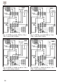
Nelle figg. 3 e 4 sono mostrati i col-
legamenti di ESPE con due uscite
statiche PNP ed a relè: le due usci-
te ad un filo sono collegate su S11
ed S22.
Il terminale negativo (A2) del
modulo è collegato al GND della
alimentazione insieme al terminale
negativo della alimentazione
dell’ESPE.
I contatti NC dei teleruttori esterni
a guida forzata vengono controllati
dal circuito di START: un eventua-
le incollaggio di uno di essi impedi-
sce al modulo la ripartenza al suc-
cessivo tentativo.
Nelle figg. 5 e 6 sono illustrati i col-
legamenti tra il modulo ed un
ESPE con una uscita ad un solo
filo: questo è collegato ad S11,
mentre S11 ed S22 sono in corto-
circuito. La categoria di sicurezza
di questa applicazione non può
essere superiore a 2.
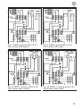
Le figg. 7 e 8 mostrano i collega-
menti tra il modulo ed un ESPE
con due uscite ciascuna a due fili
(es. PNP optoisolate oppure a relè
con contatti puliti privi di potenzia-
le): un punto comune viene colle-
gato ad S21, mentre i terminali di

uscita vengono collegati ad S11 ed
S22.
Le figg. 9 e 10 mostrano analoghi
collegamenti di un ESPE con una
sola uscita a due fili. La categoria
di sicurezza di questa applicazione
non può essere superiore a 2.
NOT
A
Per le applicazioni in categoria 4
è necessario che anche l’ESPE
sia conforme ai requisiti per la
categoria 4 secondo la normativa
EN954-1 e EN13849-1, con auto-
controllo dello stato delle uscite
sicure: in caso di guasto o corto-
circuito delle uscite sicure
dell’ESPE, questo deve rilasciare
immediatamente le stesse.
NOT
A
Il sistema ESPE + NLG13D724..
è parte del sistema di sicurezza
della macchina. Per le applicazio-
ni di categoria 2 che utilizzano
ESPE con una sola uscita, l’inte-
grità ed il corretto comportamento
del sistema deve essere verifica-
to da un dispositivo di più alto
livello (ad esempio dalla macchi-
na in cui la coppia modulo-barrie-
ra è installata oppure da un
dispositivo di controllo dei sistemi
legati alla sicurezza della macchi-
na).
Per raggiungere la categoria 2 il
sistema di sicurezza deve essere
verificato con regolarità: occorre
attivare operazioni di autocontrol-
lo dell’ESPE e di manutenzione
del sistema (vedere capitolo
“CONTROLLI PERIODICI E
MANUTENZIONE”), la cui fre-
quenza dipende dal livello di
rischio della applicazione.
Le verifiche vanno effettuate
secondo le modalità indicate nel
presente manuale (paragrafo
“MESSA In SERVIZIO”), nel
manuale dell’ESPE ed in quello
della macchina su cui il sistema è
installato, simulando a bordo
macchina il normale ciclo di lavo-
ro della barriera, interrompendo-
ne i raggi e verificando che
l’ESPE ed il modulo si comportino
come previsto.
9

10
INTRODUCTION
This user manual must be read
and completely understood, prior
to carrying out any operation on
the module, by personnel dealing
with all the activities of the
NLG13D724.. safety module.
All the operations described in this
manual must be carried out exclu-
sively by specialised personnel by
carefully following all the indica-
tions given.
The module are named
“
NLG13D724xx” where “xx” speci-
fy each model of the family.
This manual is referred to the
models with not-monitored manual
START function (”SA”), monitored
manual START function (”SC”) and
to the respective plug-in versions
(”DA” and “DC”)
The user decides under his com-
plete resposability that the safety
module is suited for the application.
FUNCTION
The safety module NLG13D724..
is designed to be employed in
safety circuits to control
ElectroSensitive Protective
Equipments (ESPE) with static
PNP outputs or relay outputs
according to 98/37/EC and
2006/42/EC Machinery Directives.
NOTE
The input terminals of the module
are intended to be:
“
operated” when the light beams
are not interrupted, the ESPE and
the module are correctly supplied
and there are not fault conditions
of the safety system: the ESPE
outputs are ON, the module is
enabled to close the safety out-
puts and the external contactors
can be energized.
“
released” when the light beams
are interrupted, or the ESPE
and/or the module are not correc-
tly supplied or there are fault con-
ditions of the safety system: the
ESPE outputs are OFF, the
module is not enabled to close
the safety outputs and the exter-
nal contactors cannot be energi-
zed.
INSTALLATION
WARNING
- The safety module must be
installed following the standards
in force in the country of use,
when the machine is not powe-
red and with no dangers for the
operator, on the machine’s elec-
trical board in a dry and clean
place (minimum protection
degree: IP54), fixed on the spe-
cial DIN rail.
- If the safety module is tampered
with, it can not ensure the safety
of the operator any more and
the warranty is void.
- To avoid interference due to
coupling, run the connecting

conductors separately from the
power conductors.
- Avoid installation during storms.
- Do not dispose of the packaging
in the environment.
WIRING
It is recommended to use conduc-
tors with section and length ade-
quate to the terminals, currents
and distances involved, ensuring
that the conductors are not exces-
sively tight, that their positioning
avoids potential cuts or squashing
and that they are not in the way of
people or things.
The models named “SA” and “SC”
are equipped with fixed screw ter-
minals for direct wiring on the
module.
The modules named with “DA” and
“DC” are equipped with plug-in ter-
minals, that allow the wiring on
female connectors far from the
module.
Once wired-on, the female con-
nectors can be connected to the
male ones fixed on the module.
TERMINALS CODING
The plug-in terminals of the “DA”
and “DC” models are coded so that
it is possible only one combination
to connect ALL the female connec-
tors on the corresponding male.
POWER SUPPLY
Connect the A1 & A2 terminals
respectively to the positive and
negative poles of the DC power
supply source. The negative sup-
ply terminal of the ESPE must be
connected to the same negative
pole of the DC power supply sour-
ce to which is connected the A2
terminal of the safety module (see
examples in this manual).
INPUT
The module is designed to be dri-
ven (input terminals S11 and S22)
by two static PNP inputs: each
ESPE PNP output transistor has
the emitter internally connected to
the supply of the ESPE, so each
ESPE output has only one wire
coming from the collector. With this
configuration the system module +
light barrier can reach safety cate-
gory 4 according to EN 954-1 and
EN13849-1.
The light barrier can be also driven
by only one static PNP input (see
the examples in this manual): with
this device the system module +
light barrier can reach safety cate-
gory 2 according to EN 954-1 and
EN13849-1.
The safety module is enabled to
close the safety outputs only if both
input contacts are operated.
The connection between the ESPE
and the safety module depends on
the ESPE outputs type as listed
below:
-
ESPE with two one-wire outputs
(PNP-type or relay-type): con-
nect one output to the S11 termi-
11

12
nal and the other to the S22 ter-
minal, leaving S12 and S21 ter-
minals not connected (fig. 3, 4
max. Safety cat. 4).
-
ESPE with one one-wire output
(PNP-type or relay-type): con-
nect the output to the S11 termi-
nal; short-circuit the terminals
S11 with S22, leaving S12 and
S21 not connected (fig. 5, 6,
max safety cat. 2).
- ESPE with two PNP two-wires
outputs (e.g. optocoupled PNP-
type): connect both emitter out-
puts to the S21 terminal and the
collector outputs to the S11 and
S22 terminal, leaving S12 not
connected (fig. 7, max. Safety
cat. 4).
-
ESPE with two relay two-wires
outputs: connect one wire of
each output channel to the S21
terminal and the other outputs to
the S11 and S22 terminal, lea-
ving S12 not connected (fig. 8,
max. Safety cat. 4).
- ESPE with one PNP
two-wires
output (e.g. optocoupled PNP-
type): connect the emitter output
to the S21 terminal and the col-
lector output to the S11 terminal;
short-circuit S11 with S22, lea-
ving S12 not connected (fig. 9
max. Safety cat. 2).
-
ESPE with one relay two-wires
output: connect the output wires
to the S11 and S22 terminals;
short-circuit S11 with S22, lea-
ving S12 not connected (fig. 10
max. Safety cat. 2).
For safety cat. 2 applications, a
periodic test (interrupting the
ESPE light beam) must be carried
out. The test periodicity is defined
in the relevant standards.
The safety relay is enabled to
close the safety outputs only if both
input switches are operated.
START CIRCUIT
The safety modules “SA” and “DA”
are set up with not-controlled auto-
matic/manual START. The module
can be employed connecting bet-
ween the S33-S34 terminals either
a NO START pushbutton (for not
monitored manual START) or a
short-circuit (for automatic
START).
The safety modules “SC” and “DC”
are set up with monitored manual
START. The module can be emplo-
yed only connecting between the
S33-S34 terminals a NO START
pushbutton (monitored also for
welding fault). These models can-
not be configured for automatic
START.
SAFETY OUTPUTS
Three NO voltage free safety out-
puts are available between the 13-
14, 23-24 and 33-34 terminals:
their contacts are closed when the
safety module is correctly powe-
red, the input switches are opera-

ted, and the START circuit has
been activated, as described in
this user manual.
AUXILIARY OUTPUT
An auxilary NC voltage free relay
output is available between the 41-
42 terminals. It must be used only
for signalling functions and not for
safety functions.
OPERATING MODE
With manual START configuration,
the safety outputs close, if the swit-
ches connected to S11 & S22 are
operated, when the NO START
pushbutton is pushed. With auto-
matic START configuration, the
safety outputs close as soon as
both the switches connected to
S11 & S22 are operated. The CH1
& ChH2 LED turn on.
Releasing even one input contact
(S11 and/or S22) forces immedia-
tely the safety outputs to an open
status. The LED relative to the
channel whose input has been
released turns off.
A new operating cycle is possible
only after releasing both input con-
tacts and then operating them
again (and pushing the START
button, if the safety module has
been set up with manual START
configuration).
For the “SC” and “DC” models it is
necessary a minimum delay of 500
ms from the operated status of the
input contacts to the pushing of the
START button. The same delay is
necessary between the START
button releasing and re-operating,
if the input terminals have been
previously operated with the
START button already pushed.
In the models with monitored
manual START configuration, if the
NO START button gets welded, the
safety outputs cannot close their
contacts any more.
TEST & ACTIVATION
The following operations must be
repeated when the module is
installed and every time the wiring
is changed and at regular intervals
by carrying out in sequence all the
steps described below avoiding
any type of dangerous condition
for the operators.
STEP 1 Check the integrity, the
correct installation, the correct
positioning on the machine and the
correct functioning of all the devi-
ces connected to the inputs and to
the outputs of the safety module.
Check also the correct wiring of all
the devices.
STEP
2
Power on the safety
module: the
POWER LED turns on
(this LED has to be considered ON
in all the steps of this sequence).
The CH1 and CH2 are off.
Operate the input contacts: the
safety outputs are open and the
CH1 & CH2 are off (if the module is
configured for automatic START,
13

14
CHA1 & CH2 turns on and the
safety outputs close).
Close the START contact: the
safety outputs close and the
CH1,
CH2 LED turn on.
STEP 3 Release both input con-
tacts: the safety outputs open and
the
CH1, CH2 LED turn off.
During STEP 2 check that the
safety outputs do not close - with
manual START configuration - sim-
ply operating both input contacts,
without pushing the START
pushbutton.
STEP 4 (This step must be perfor-
med first on one input contact,
S11, then on the other one, S22
and only for 2-outputs ESPE).
Repeat the procedure from STEP
2, operating both input switches
(and START contact for manual
START configuration, so that the
safety outputs are closed), and
then releasing / disconnecting only
one of them and checking that the
safety outputs open: re-operate/re-
connect the input switch, push the
START button and check that the
safety outputs do not close.
The STEPS 3 and 4 must be
repeated for each input device
connected to the input terminals.
NOTE
During all steps verify that the
auxiliary output is closed when
the safety outputs are open and
that the auxiliary output is open
when the safety outputs are clo-
sed.
USAGE PRECAUTIONS
- The ESPE must be carefully
installed and positioned in order
to reach a high protection level
for the operator.
The European Standards state
the minimum distance between
the ESPE and the hazardous
area, in order to avoid the possi-
bility for the operator to reach
the hazardous area when the
conditions are still dangerous.
These distances depend on the
stopping time of the machine, on
the response time of the module
+ ESPE, on the resolution, on
the distance from the ground (for
horizontal mounting) of the
ESPE, and on the speed of the
operator approaching to the
dangerous area.
All plants must fully comply with
the requirements of the stan-
dards listed above and of all the
standards involved in each spe-
cific application.
- The safety module can check
the integrity of external contac-
tors or expansion modules sim-
ply connecting their NC control
contacts in series to the START
contact (or to the bridge, in auto-
matic START configuration) bet-
ween S33-S34 terminals.
- It is recommended to connect a

fuse in series to the safety out-
puts to reduce the risk of the
safety outputs contacts welding
(see outputs technical data).
- Never, in any situation,connect
spark quenching unit circuits in
parallel to safety outputs con-
tacts: the safety function would
no longer be guaranteed.
- Never, in any circumstance,
exceed the electrical ratings sta-
ted in the technical data table of
this manual.
INSPECTIONS AND
MAINTENANCE
The integrity of the module and of
all the connected devices must be
checked regularly according to the
risk evaluation of the plant, under
the complete responsibility of the
user. Regular inspections must be
performed repeating all the opera-
tions listed in the TEST & ACTIVA-
TION section.
In particular it is necessary to per-
form regular tests on board in
order to verify that the input devi-
ces are not faulted.
In the event of a switch-off of the
module or of the machine it is
necessary to repeat all the opera-
tions listed in the TEST & ACTIVA-
TION section in order to verify the
integrity of the module + external
device system.
The safety module doesn’t require
internal maintenance: it must be
periodically cleaned - with plant
and module powered off - together
with all the connected devices,
removing dust, liquids and conden-
sation.
APPLICATIONS
In Fig. 3 and 4 are shown the con-
nections of ESPE with 2 one-wire
outputs: the ESPE outputs are
connected to S11 and S22.
The negative supply terminal (A2)
of the module is connected to the
GND terminal of the power supply
source together with the negative
supply terminal of the ESPE.
The N.C. contacts of the external
contactors are monitored by the
START circuit: if one contact gets
broken, the safety outputs of the
module can not close any more
during the next START cycle.
The category of the application can
reach up to category 4 according
to the EN954-1 and EN13849-1
standards.
In Fig. 5 and 6 are shown the con-
nections of ESPE with 1 one-wire
output: the ESPE output is connec-
ted to S11 and S22 is short-circui-
ted to S11. The category of the
application can reach up to catego-
ry 2 according to the EN954-1 and
EN13849-1 standards.
In Fig. 7 and 8 are shown the con-
nections of ESPE with 2 two-wires
15

16
outputs: one ESPE common point
is connected to S21, while the out-
puts are connected to S11 and
S22. The category of the applica-
tion can reach up to category 4
according to the EN954-1 and
EN13849-1 standards.
In Fig. 9 and 10 are shown the
connections of ESPE with 1 two-
wires output: one ESPE output
wire is connected to S21, while the
other is connected to S11 and S11
is short-circuited with S22.
The category of the application can
reach up to category 2 according
to the EN954-1 and EN13849-1
standards.
As the input switches, connected
to the S11 and S22 inputs are ope-
rated, the safety module is enabled
to close the safety outputs, in
manual START set-up, or closes
the safety outputs, in automatic
START set-up.
NOTE
To reach the safety category 4
the ESPE must be compliant with
the requirements of safety cate-
gory 4 according to EN 954-1 with
self-monitoring for the event of
short-circuit between its outputs:
in the event of short-circuit betwe-
en the ESPE safety outputs the
ESPE must switch off the safety
outputs.
NOTE
The ESPE + NLG13D724..
module system is part of the safe-
ty devices of the machine. For
safety category 2 applications
employing ESPEs with only one
output, the integrity and correct
behaviour of the system must be
monitored by the overall safety
system in which the ESPE and
the module are used (e.g. the
machine in which the ESPE is
installed or a safety supervisor).
To reach safety category 2 the
safety system must be checked
and monitored regularly. Self-
checking functions of the ESPE,
manual tests and regular mainte-
nance activities (see chapter 7)
must be performed by the user
with a frequency suited for the
risk of the application. The check
must be performed according to
the “TEST AND ACTIVATION”
chapter of this manual and accor-
ding to the checking procedures
of the ESPE user’s manual, simu-
lating on board the normal wor-
king cycle of the ESPE, interrup-
ting the ESPE beams and veri-
fying that the ESPE and the
module work correctly.

FIGURE E TABELLE / FIGURES AND TABLES
17
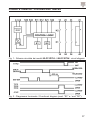
Fig. 1 - Schema circuitale dei moduli NLG13D724.. / NLG13D724.. circuit diagram
Fig. 2 - Diagramma funzionale / Functional diagram (mod. “SC” e / and “DC”)

18
Fig. 3: ESPE: 2 uscite PNP a 1 filo /
Two 1-wire PNP outputs
Fig. 4: ESPE: 2 uscite a relè a 1 filo /
Two 1-wire relay outputs
Fig. 5: ESPE: 1 uscita PNP a 1 filo /
One 1-wire PNP output
Fig. 6 ESPE: 1 uscita a relè a 1 filo /
One 1-wire relay output

19
Fig. 10: ESPE: 1 uscita a relè a 2 fili /
One 2-wires relay output
Fig. 9: ESPE 1 uscita PNP a 2 fili /
One 2-wires PNP output
Fig. 7: ESPE: 2 uscite PNP a 2 fili /
Two 2-wires PNP outputs
Fig. 8: ESPE: 2 uscite a relè a 2 fili /
Two 2-wires relay outputs

20
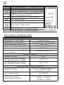
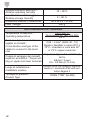
DATI TECNICI / TECHNICAL DATA
TERM COLLEGAMENTI / CONNECTIONS
A1 Positivo Alimentazione DC / DC Positive supply
A2 Negativo Alimentazione DC / DC Negative supply
S33-S34
Contatto di START e ritorno teleruttori esterni /
START and feedback terminals
S11, S22 Canali di ingresso NO / NO Input channels
S12 Non usato / Not Used
S21 Comune NO / NO Common-Input terminal
13-14
23-24
33-34
Uscite sicure / Safety outputs
41-42 Uscita ausiliaria NC / NC auxiliary output
Tab. 1 - Funzioni dei terminali / Terminals description
Fig.11 - Etich. fron-
tale / Front label
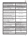
CARATTERISTICHE / CHARACTERISTICS
Alimentazione / Power supply 24 Vdc -15/+10%
Assorbimento / Current drain 70 mA (@ 24Vdc, a vuoto/no load)
Potenza assorbita / Power Drain max 5 VA
Categoria sic. / Safety Category 4 (EN954-1 and EN13849-1)
Performance Level e (EN13849-1)
Protezione al corto circuito / Short-
Circuit Protection
PTC interno / Internal PTC
INGRESSI / INPUTS
Funzione / Function 2 N.O.
Corrente/Tensione min.operativa
Min. Operating Current / Voltage
10 mA / 17 V
Corrente/Tensione max.operativa
Max. Operating Current / Voltage
30 mA / 38 V
USCITE SICURE / SAFETY OUTPUTS
Funzione / Function
Contatti N.O. a guida forzata / N.O.
Force-Guided Contacts
Caratteristiche / Ratings (carico resi-
stivo /
resistive load)
AC 230/240 V; DC 250 V
6A / 1380 VA
Protezione dei contatti /
Output contacts protection
Fusibile esterno / External fuse: 4 A
ritardato / 5 A rapido
4 A delayed / 5A fast
La pagina si sta caricando...
La pagina si sta caricando...
La pagina si sta caricando...
La pagina si sta caricando...
-
 1
1
-
 2
2
-
 3
3
-
 4
4
-
 5
5
-
 6
6
-
 7
7
-
 8
8
-
 9
9
-
 10
10
-
 11
11
-
 12
12
-
 13
13
-
 14
14
-
 15
15
-
 16
16
-
 17
17
-
 18
18
-
 19
19
-
 20
20
-
 21
21
-
 22
22
-
 23
23
-
 24
24


CARLO GAVAZZI NLG13D724SC Manuale utente
- Tipo
- Manuale utente
- Questo manuale è adatto anche per
in altre lingue
Documenti correlati
-
CARLO GAVAZZI NLG02D724SC Guida d'installazione
-
-
-
-
-
-
