


ZUMMO-INNOVACIONES MECÁNICAS, S.A. en su constante afán por mejorar sus
productos, se reserva el derecho de modificar las máquinas sin previo aviso; por este motivo el
presente libro de instrucciones puede omitir los últimos cambios efectuados.
INDICE
........................................................................................................................................... Pág.
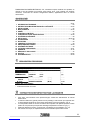
1 DATOS TECNICOS .............................................................................................................. 03
2 INSTRUCCIONES IMPORTANTES DE SEGURIDAD ....................................................... 03
3 INSTALACION .................................................................................................................... 04
4 PUESTA EN MARCHA .................................................................................................. 04-05
5 PARO ................................................................................................................................... 05
6 FUNCION CONTADOR ....................................................................................................... 05
7 FUNCIÓN BLOQUEO DEL SELECTOR ............................................................................. 05
8 SISTEMAS DE SEGURIDAD ............................................................................................... 06
9 LIMPIEZA ....................................................................................................................... 06-07
10 ACCESORIOS ..................................................................................................................... 08
11 MANTENIMIENTO ................................................................................................................ 08
12 CONSEJOS DE UTILIZACION ........................................................................................... 08
13 LOCALIZACIÓN DE AVERIAS ...................................................................................... 08-09
14 ESQUEMA ELÉCTRICO ..................................................................................................... 09
15 LISTADO DE COMPONENTES .......................................................................................... 10
16 GARANTIA .......................................................................................................................... 11
17 RESIDUOS Y RECICLABILIDAD ........................................................................................ 12
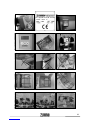
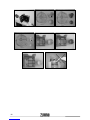
18 FOTOS ............................................................................................................................ 83-84
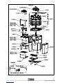
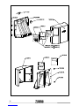
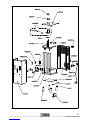
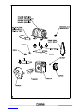
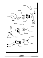
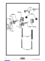
19 PLANOS DE DESPIECES ............................................................................................. 85-90
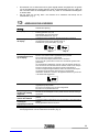
1DATOS TÉCNICOS
CONSUMO (W) 275
NARANJAS POR MINUTO 11
CAPACIDAD ALIMENTADOR 9Kg
DIMENSIONES
ALTO (mm) 788
ANCHO (mm) 478
FONDO (mm) 444
TAMAÑO DE LA
FRUTA
Ø (mm)
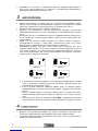
COPAS PEQUEÑAS * (Ø 60) 53-60
COPAS MEDIANAS (Ø 75) 55-75
70-90
PESO (Kg.) (sin embalaje) 55
* accesorio no incluido de serie.
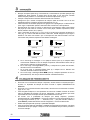
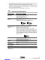
2 INSTRUCCIONES IMPORTANTES DE SEGURIDAD
x Estimado cliente: Antes de usar su máquina exprimidora, por favor, lea atentamente el
manual de instrucciones.
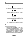
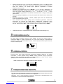
x La máquina ejerce una gran presión al exprimir; por esta razón, no introduzca nunca ni las
manos ni objetos extraños en la zona de exprimido. (Fig. 9)
x No se deje nunca flojas las tuercas de sujeción de las copas ni de la bandeja exprimidora;
de lo contrario, podría ocasionar serios daños en la máquina. (Fig. 1)
x Tenga especial cuidado con la cuchilla, podría cortarse al manipularla. (Fig. 12)
x Para evitar riesgos, toda reparación debe hacerse por personal técnico.
x No se acepta responsabilidad alguna si la razón del daño es el mal uso del aparato o el no
haber seguido las instrucciones de este manual.
x Solicite el servicio de asistencia técnica a la empresa que le suministró la máquina; en caso
de no localizarla, contacte con el fabricante (datos en la portada de este manual).
3
COPAS GRANDES (Ø 90)

3 INSTALACION
x ¡Atención! la máquina pesa 55 Kg. Para trasladar la máquina, le aconsejamos que la cojan
entre dos personas. La mejor forma de cogerla es sujetar con una mano, por debajo del
trasero y la otra mano debajo de la bandeja exprimidora. (Fig. 6)
x Coloque la máquina sobre una base suficientemente fuerte y estable.
x Asegúrese de que la tensión y frecuencia de la máquina coincide con su instalación
eléctrica. Vea la placa de matrícula. (Fig. 2)
x Utilice una base de enchufe provista de una eficaz toma de tierra protegida por un
diferencial de 0,03A conecte a esta base sólo la máquina exprimidora. No la comparta con
otros aparatos.
x Se recomienda que antes de poner en funcionamiento la máquina, se efectúe una limpieza
de las piezas que van a estar en contacto con el zumo (copas, bandeja exprimido, bolas,
cuchilla, bandeja filtro, filtro y carátula).
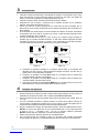
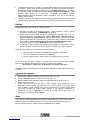
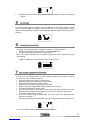
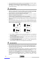
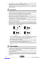
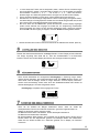
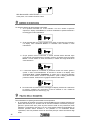
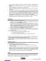
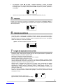
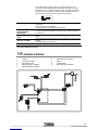
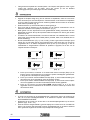
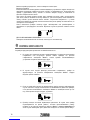
x Conecte el interruptor de red. (Fig. 3 ( I=On, O=Off )). Si no aparece ningún mensaje en
pantalla, (Fig. 4) el motivo será falta de tensión; en este caso, deberá asegurarse de haber
conectado el enchufe a una línea con tensión y que el interruptor de red esté accionado.
Una vez subsanado este problema, aparecerá uno de estos mensajes:
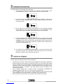
(Disp. 2) (Disp. 5)
MEM
(Disp. 6) (Disp. 9)
a. Si aparece en pantalla el mensaje “3” o cualquier número (Disp. 2), la máquina esta
dispuesta con todo correcto y seleccionadas las naranjas a exprimir. En este caso ya
puede poner en funcionamiento la máquina.
b. Si aparece en pantalla el mensaje Error (Disp. 5), la máquina tiene la carátula mal
colocada, deberá colocarla correctamente.
c. Si aparece en pantalla el mensaje Error (Disp. 6), la máquina tiene la bandeja mal
colocada, deberá colocarla hasta el fondo.
d. Si aparece en pantalla el mensaje Error MEM (Disp. 9), la máquina tiene un error en la
placa electrónica, en este caso deberá llamar al servicio técnico.
4 PUESTA EN MARCHA
x Según el tamaño de naranjas que vaya a exprimir debe elegir el tamaño de copa y bola y el
separador de naranjas de la cesta. Vea el capitulo ACCESORIOS MÁQUINA.
x Según el tamaño de bola que haya elegido, debe colocar las gomas en la cuchilla. (Figs. 20
-21 – 22)
x Una vez conectada la máquina, el display muestra un número del 1al 50 o la letra C. El
número indica la cantidad de naranjas que se van a exprimir y la letra C significa que se
exprimirá ininterrumpidamente durante 30 minutos aproximadamente.
x Según la cantidad de naranjas que usted desee exprimir, pulse intermitentemente el botón
SELECT, el número que aparece en el visor irá aumentando del 1 al 50 y luego aparecerá
la letra C. (1,2,3,..........48,49,50,C,1,2,3.....) Si por el contrario mantiene presionado
SELECT durante más de 2 segundos, el número irá disminuyendo.
x Realice esta operación hasta que aparezca la cantidad deseada.
x Una vez seleccionada una cantidad y realice un exprimido, esta quedará memorizada
aunque apague la máquina y no cambiará hasta que vuelva a hacer una nueva selección.
4

x Al pulsar el botón ON del panel, la máquina exprimirá el número de naranjas que muestra
el display, indicando durante el proceso el nº de naranjas que le falta por exprimir. Si desea
repetir la operación, basta con pulsar ON. Para detener el proceso pulsar el botón STOP.
x No poner nunca la mano en la cesta cuando la máquina está trabajando. (Fig.23)
5 PARO
Estando en marcha, pulse el botón de Stop. El display muestra un Reloj y Stop y la máquina
se detiene cuando las copas llegan a la vertical. Después el display muestra el número de la
anterior selección.
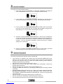
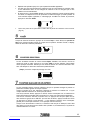
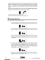
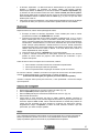
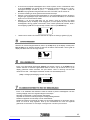
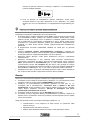
6 FUNCION CONTADOR
Si desea conocer el número total de pasos* realizados, deberá, con la máquina parada y
dispuesta, apretar el botón STOP y en el display se visualizará dicha cantidad durante unos
segundos. Tenga en cuenta que de fábrica todas las máquinas salen con 400 – 500 pasos
debidos a las pruebas para el control de calidad.
*(paso= maniobra completa de exprimido de una fruta)
COUNTER
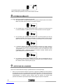
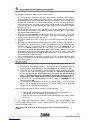
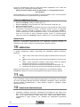
7FUNCIÓN BLOQUEO DEL SELECTOR
Si desea dejar el botón selector anulado para que no se pueda modificar la cantidad de
naranjas a exprimir, proceda del siguiente modo:
Seleccionar el número que se quiera memorizar.
Mover la máquina y dejar que acabe el ciclo completo.
Apagar la máquina desde el interruptor de red.
Con la máquina apagada (carátula y bandeja posición indistinta), pulsar STOP, mantener
pulsado y accionar el interruptor de red, mantener pulsado durante cuatro segundos y
aparecerá una pantalla con cuatro números.
Una vez conseguida esta pantalla buscar el número 7437, pulsando ON controlaremos los
dos dígitos de la izquierda y pulsando SELECT los dos de la derecha, luego pulsar STOP (al
pulsar STOP el display pasará a mostrar ----) y después apagar la máquina con el interruptor
de red (si no se apaga la máquina, no se sale de esta pantalla).
Al volver a conectar la máquina el selector estará bloqueado o desbloqueado según el estado
en el que estuviera antes de hacer esta operación y en su caso se visualizará el símbolo del
candado en el display.
PARA DESBLOQUEAR EL SELECTOR.
Lo mismo que antes, con el mismo número de código.
5

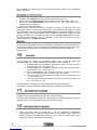
8SISTEMAS DE SEGURIDAD
La máquina dispone de varios sistemas de seguridad:
1Si la carátula no está bien colocada o el techo no está puesto, el display muestra
Error, y están la carátula y la cesta de forma intermitente.
2Si la bandeja filtro no está encajada en sus sitio, la máquina no funciona y en el
display se muestra Error. La bandeja esta sombreada y de forma intermitente.
3Si por algún motivo la máquina, estando en marcha, quedara bloqueada,
automáticamente pasados unos segundos se pararía el motor y en el display se
mostraría Error e Icono intermitentes, quedando a la espera de que se elimine la
causa del bloqueo.
4La máquina dispone de un sistema de protección térmica en el motor; gracias a
éste, en caso de un recalentamiento, se detiene la máquina y en el display se
muestra Error e Icono Termómetro. En tal caso, deberá esperar
aproximadamente diez minutos para que baje la temperatura; entonces el display
cambiará a posición normal. Verifique que las rejillas de aireación están libres.
5Si la máquina no muestra ningún mensaje en el display, será debido a falta de
tensión. Compruebe que el interruptor de red esté accionado y que el fusible de
seguridad de la base de red no esté fundido (Fig.16).
9 LIMPIEZA MAQUINA
Recomendamos una limpieza diaria de la zona de exprimido.
x Se recomienda parar la máquina presionando Stop antes de cualquier operación de
limpieza de la máquina (nunca parar del interruptor principal), ya que de esta forma todas
las piezas a limpiar se encontrarán situadas en una posición de fácil extracción y
colocación. En caso de no seguir esta recomendación la máquina podría parar en una
posición en la que le resultara difícil dicha operación lo que podría acarrear rotura de
piezas por mala colocación de las mismas.
x Con la máquina parada siguiendo el proceso anterior DESCONECTE LA MÁQUINA DEL
INTERRUPTOR DE RED. (Fig. 3). El display del selector digital se apagará.
x Extraiga la carátula y límpiela con un paño húmedo bañado en una solución jabonosa
neutra (¡ATENCIÓN!: no limpiarla NUNCA con productos que puedan rayarla).
x Sacar la bandeja filtro para tener acceso a las tuercas que fijan la bandeja de exprimido.
6

desenrosque también las bolas que están dentro de la bandeja exprimido (Fig. 5); debajo
de cada una de ellas debe haber una arandela ¡tenga cuidado de no perderlas!. Puede
introducir estas piezas en el lavavajillas o limpiarlas manualmente. TENGA
ESPECIALMENTE MUCHO CUIDADO CON LA CUCHILLA (Fig. 12) ya que está muy
afilada y podría cortarse.
x Para sacar las copas le aconsejamos que desenrosque ligeramente las tuercas de sujeción
y apoyándose en ellas, tire hacia afuera; quedarán sueltas y podrá sacarlas con facilidad.
Montaje
Después de lavarlo todo, móntelo en el siguiente orden:
1Enrosque las bolas en la bandeja exprimido. Tenga cuidado de volver a colocar
previamente las arandelas y de ¡APRETAR! bien las bolas.
2Revise que la cuchilla tenga las gomas correctamente colocadas (Fig. 10 y 11).
Introduzca la cuchilla en el interior de la bandeja. Monte dicho conjunto por los tres
ejes de la máquina simultáneamente. Atención para encarar la cuchilla con su eje,
presione ligeramente de las paredes de la cuchilla hacia abajo y tenga mucho cuidado
de no cortarse ¡¡Nunca ensamble la cuchilla sobre la bandeja posteriormente!!.
3Coloque las copas en los ejes y APRIETE bien las tuercas de sujeción.
4La carátula se coloca introduciendo las dos partes superiores por las ranuras, cuando
las coloque notará un pequeño ruido como que han encajado y la maquina esta lista.
Antes de volver a poner en funcionamiento la máquina, observe:
x Que la bandeja y la cuchilla han quedado bien encajados y atornillados.
x Que las tuercas de las copas están bien apretadas.
x Que los juegos de bolas y copas (mismo color la pareja) son los correctos.
En el caso de que la cuchilla, la bandeja, las bolas o las copas no quedaran bien colocadas
podrían ocurrir daños en dichas piezas e incluso en el interior de la máquina.
(Problemas no cubiertos por la garantía por ser fallos del operador)
Cuando la máquina esta lista para funcionar el display mostrará el número de naranjas que va
a exprimir.
Limpieza del cargador
x Desenrosque la tuerca que está en el interior de la cesta. (Fig. 13)
x Saque el separador tirando del mismo hacia arriba. (Fig. 14)
x Saque la cesta tirando hacia arriba hasta que salga totalmente de su eje. (Fig. 15)
x Saque la pista de la tolva.
x Limpie todos sus elementos con agua y jabón, también puede introducirlos en el
lavavajillas. Vuelva a montar siguiendo este orden: primero coloque la pista de la tolva,
luego la cesta en el eje, después gire la cesta manualmente en el sentido horario hasta
que quede encajada (los pivotes habrán entrado en sus agujeros respectivos). A
continuación coloque el separador en el interior de la cesta, haciendo que encaje y no
pueda girar, por último enrosque la tuerca.
Nota:
Con el uso de la máquina puede que se produzca una pigmentación de color naranja en las
partes de plástico que están en contacto con el zumo, esto es completamente normal y no
supone problema higiénico ni afecta a las propiedades físicas del plástico.
7
x La bandeja de exprimido y la cuchilla se extraen desenroscando las tuercas de los ejes de
la bandeja y tirando hacia afuera horizontalmente. Si desea una limpieza exhaustiva,

10 ACCESORIOS MÁQUINA
Según el tamaño de la fruta que se quiera exprimir, la máquina dispone de varios juegos de
copas y bolas a elegir:
aCopas y bolas de color gris oscuro, para frutas de diámetro entre 55 – 75mm
(Fig. 18)
bCopas y bolas de color gris claro, para frutas de diámetro entre 70 – 90mm
(Fig. 17).
cCopas y bolas pequeñas, de color gris muy claro, para frutas de diámetro entre
53 – 60mm (Fig. 19). (Opcional)
dSeparador cesta para las naranjas de diámetro 70 – 90mm. (Fig. 17)
eSeparador cesta para naranjas de diámetro 53 - 75mm. (Figs. 18-19)
Independientemente del juego que se monte, la cuchilla siempre será la misma.
¡ATENCIÓN!: no deben mezclarse elementos de distintos juegos.
11 MANTENIMIENTO MÁQUINA
El mantenimiento exterior de la máquina se limita a su limpieza.
En el interior de la máquina cada 600.000 naranjas se deben engrasar las guías, sustituir los
muelles y realizar una limpieza exhaustiva.
12 CONSEJOS DE UTILIZACIÓN
x Procure que las naranjas entren bien en las copas que elija para exprimir, pues si la copa
es demasiado pequeña, pellizcará la corteza y sacará aceite, en este caso el zumo tendrá
sabor amargo.
x Para obtener la mayor cantidad de zumo posible, es conveniente que las copas no sean
mucho mas grandes que las naranjas que esté utilizando.
x El separador de naranjas de la cesta debe ajustar lo mejor posible a las naranjas que se
estén utilizando. Si las naranjas son grandes, estas no caerán a la copa. Si las naranjas
son demasiado pequeñas, caerán varias naranjas en la copa.
x Cuando finalice la jornada apague la máquina utilizando el interruptor de red. (Fig. 3)
13 LOCALIZACION DE AVERIAS
Avería Causa y/o solución
El display no se ilumina Falta tensión eléctrica en la red.
Fusible fundido. (Fig. 16)
Cable de red mal conectado.
Accione el interruptor de red. (Fig. 3)
Humedad en placa electrónica. Proporcionar calor seco a la placa.
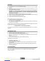
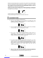
Aparece Error en el
display
Carátula mal colocada (Disp. 5). (Fig. 7)
Pista tolva mal colocada. (Disp. 5)
Bandeja filtro fuera de su sitio (Disp. 6). (Fig.8)
Disp. 5 Disp. 6
8

intermitente en el
display.
Observe si se han amontonado cortezas en la bandeja exprimidora.
Vea si se ha dejado las bolas desenroscadas.
Vea si las cortezas se quedan pegadas en el interior de las copas.
Compruebe que no ha montado copas y bolas de diferentes tamaños.
Para desbloquear la máquina utilizar una llave allen de 5mm que
encontrará a la derecha de la rejilla inferior de la máquina. Introducirla en
el agujero del lateral derecho, y con la máquina desconectada, girar en
sentido horario hasta subir las copas y deshacer el bloqueo. ATENCIÓN:
antes de conectar la máquina, asegúrese de que ha sacado la llave de su
anclaje.
Rotura de la cuchilla Se han soltado las gomas y se amontonan las cortezas en la bandeja de
exprimido.
Tuercas de las copas mal apretadas.
Las bolas de la bandeja exprimidora estaban sueltas.
Las naranjas no quedan
suficientemente
exprimidas
Falta la rejilla interior Z14.
La corteza de la naranja es demasiado fina; coloque como máximo una
arandela en cada bola.
Las naranjas no caen de
la cesta
Uso de naranjas demasiado grandes para el separador de cesta que está
utilizando.
Caen varias naranjas a
la vez a la copa
Uso de naranjas demasiado pequeñas para el separador de cesta que
está utilizando.
Cesta mal anclada. Ver punto nº 9.
Para cualquier consulta o petición de repuestos, deberá indicar modelo y número de
matrícula de su máquina (Fig. 2).
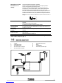
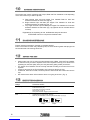
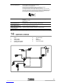
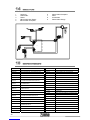
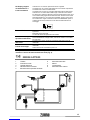
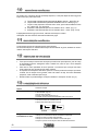
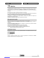
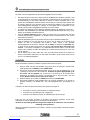
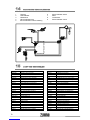
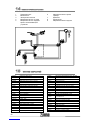
14 ESQUEMA ELECTRICO
1 Fusible
2 Interruptor de red
3 Placa electrónica
4 Microinterruptor contador
5 Microinterruptor carátula
6 Microinterruptor techo
7 Motor
8 Condensador
9 Microinterruptor bandeja
9
8
7
6
5
4
3
2
1
9
Aparece Error e Icono Vea si está exprimiendo naranjas congeladas.

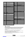
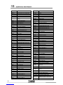
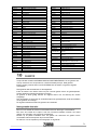
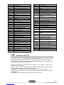
15 LISTADO DE COMPONENTES
0504001A REDUCTOR CUÑAT SX-50
0504002B MOTOR 0,33CV, 225V-50Hz
0504003A MOTOR BIFAS. 033CV 240/250V-50Hz
0504003B MOTOR BIFAS. 0.33CV 115V-60Hz
0504003C MOTOR BIFAS. 0.33CV 220V-60Hz
0504004A POLEA MOTOR 16XL
0504005 POLEA ENTRADA REDUCTOR (60XL037)
0504007 ARANDELA BULON Y EJE REDUCT.
0504013 PASADOR CHAPA EMPUJADORA
0504014-1 CORREDERA COPAS CON INSERTO
0504019 CORREA DENTADA 190 XL 0.37
0504024 GOMA DE FRENO
0504026 EJE SALIDA REDUCTOR SX-50
0505010A TUERCA COPAS CON JUNTA
0505010A-1 TUERCA COPAS
0505010A-2 JUNTA 20 PARA TUERCA
0505016 GOMA EXTRACCIÓN CORTEZA
0506006/1 FLEJE MICRO BANDEJA
0506007 MICRO CORTO
0506008 MICRO LARGO
0506010 CABLE DE RED
0506014 BASE DE RED CON FUSIBLES
0506015 INTERRUPTOR BIPOLAR NEGRO
0506021 PASAMURO CHAPA ZUMMITO
0506027 TAPON PLÁSTICO Ø17,3
0508013 SOPORTE DE GOMA 85mm
10/21 CONDENSADOR 30μF (motores 230V)
10/25 CONDENSADOR 100μF (motores 115V)
10/28 CONDENSADOR 22μF (motores 240V)
1011028 MICROINTERRUPTOR PALANCA 60g.
1401A00 CONJUNTO CHASIS
1401B00 CIERRE CHASIS
1402001 FRENTE
1402002 CUBRE CORREDERA COPAS
1402003 CARÁTULA Z14
1402004 LATERAL EXTERIOR
1402005L LATERAL INTERIOR IZQUIERDO
1402005R LATERAL INTERIOR DERECHO
1402006 TRASERO
1402007A TAPA INFERIOR
1402008 TAPA SUPERIOR
1402009 TAPON LATERAL
1402010 SERIGRAFÍA TRASERA
1402011 CUBRE CORREDERA CUCHILLA
1402014 PASAMUROS GOMA
1402015 SUPLEMENTO CORREDERA COPAS Z14
1403001 PISTA TOLVA
1403002 ACCINADOR ALIMENTADOR
1403003 BULONES CESTA
1403004 COJINETE CESTA
1403005 SEPARADOR 50-75
1403006 SEPARADOR 70-90
1403007 CESTA
1403008 DIVISOR
1403008-1 CILINDRO DIVISOR Z14
1403009 LENGÜETA
1403010 SECTOR TOLVA
1403011 SOPORTE LENGÜETA
1403012 CESTA Z14 COMPLETA
1404001 PIÑÓN
1404003 BIELA
1404004 RESORTE CORREDERA COPA
1404005 TIRANTE CORREDERAS COPA
1404007 CORREDERA PUENTE
1404008 CORREDERA CUCHILLA
1404009 CORREDERA TIRANTE
1404010 BULÓN BIELA SUPERIOR
1404011 BULÓN RODAMIENTO
1404013 SOPORTE TIRANTES COPAS
1404019 PUENTE CORREDERA COPAS
1404020 POLEA MOTOR 14XL 0.50
1404021 CORREA 190 XL 0.50
1404024 ANCLAJE MOTOR Z14-09
1404A00 CONJUNTO EMPUJADOR
1404B00 CONJUNTO SOPORTE CUCHILLA
1404C00 CONJUNTO COPIADOR
1405001 FILTRO 3mm Z14
1405002 FILTRO 4mm Z14
1405003 BANDEJA FILTRO Z14
1405004A EJE COPAS
1405005 BANDEJA EXPRIMIDO Z14
1405006 COPA GRANDE Z14
1405007 BOLA GRANDE Z14
1405008 COPA MEDIANA Z14
1405009 BOLA MEDIANA Z14
1405010 COPA PEQUEÑA Z14
1405011 BOLA PEQUEÑA Z14
1405012 CUCHILLA Z14
1405013 EJE CON PLETINA
1405015 REJILLA INTERIOR Z14
1405017 SUPLEMENTO EJE IZQUIERDO
1405018 SUPLEMENTO EJE DERECHO
1406001 BASE PLACA CPU
1406002 CPU 220/240V-50/60Hz
1406002A CPU 110V-50/60Hz
1406003 SOPORTE MICRO CONTADOR
1406004 SOPORTE MICRO BANDEJA
1406006 SERIGRAFIA CPU
1406007 SOPORTE MICRO TECHO
1408001 CUBETA Z14
1408002 BASE CUBETAS
1408003 BANDEJA GOTEO Z14
1408004 REJILLA GOTEO
1408005 DISCO Ø28X3 CAUCHO ESPONJOSO
NEGRO ADH.
1408009 GUIA BASE (Opcional)
3/4/3 ARANDELA INTERMEDIA (PLÁSTICO)
I-125-M10 INOX. ARANDELA PLANA M-10 DIN-125
I-965-M4x10 INOX. TOR. AVELLAN. M4x10
I-7981-Ø5,5X22 INOX. TOR. ROSCA CHAPA Ø5,5X22
I-7982-Ø3,5x9,5 INOX. TOR. ROSCA CHAPA Ø3,5x9,5
ROD.608ZZ RODAMIENTO
T-912-M8x90 TORNILLO ALLEN M8x90
T- Ø30/15/30-
M6
AMORTIGUADOR SOPORTE MOTOR
T- Ø30/15/30-M6
V0070 LLAVE ALLEN 5mm
V0071 SOPORTE LLAVE ALLEN
V0163 ADHESIVO SEPARADOR 50-75
V0164 ADHESIVO SEPARADOR 70-90
10
1404002A PUENTE

16 GARANTIA
ZUMMO-INNOVACIONES MECÁNICAS, S.A. a través de su distribuidor oficial, garantiza sus
máquinas por un período de 3 AÑOS o 200.000 ciclos de exprimido, que entrará en vigor a
partir de la fecha de ENTREGA al distribuidor, de acuerdo a las siguientes condiciones:
Esta garantía cubre todo defecto de los materiales o fabricación.
Si la máquina muestra algún defecto durante su uso normal dentro del período de garantía, las
piezas defectuosas serán reemplazadas sin cargo.
La garantía tendrá validez solamente cuando se presente la factura original de compra.
La reparación o sustitución de piezas durante el periodo de garantía, no implica una extensión
de la fecha de finalización de esta.
Los repuestos originales ofrecen una garantía de 6 meses.
Esta garantía no cubre
Cualquier daño no causado directamente por defecto de fabricación o en los materiales.
Cualquier daño debido a una incorrecta instalación, abuso, uso indebido, alteración, accidente
o negligencia.
El rayado de cualquiera de las piezas de plástico por utilizar elementos que puedan ocasionar
rayado como los estropajos en la limpieza.
Mano de obra de reparaciones no incluida en esta garantía.
Cualquier daño causado por personal o materiales no autorizados.
Los defectos causados por desgaste de uso; en particular el siguiente componente:
x 0505016 GOMA EXTRACCIÓN CORTEZA.
Asistencia técnica
Para cualquier consulta técnica, preferentemente debe ponerse en contacto con su distribuidor
habitual, o puede dirigirse a Zummo a través de:
E-mail: [email protected]
Teléfono: 961.301.246
Fax: 961.301.250
Cualquier reparación durante el período de garantía, no autorizada por ZUMMO, causará
automáticamente la anulación de esta.
11

17 RESIDUOS Y RECICLABILIDAD
Equipos fuera de uso
Unión Europea
Este símbolo indica que los aparatos eléctricos y electrónicos que lo llevan
no deben desecharse junto con la basura doméstica general. Si desea
desechar este equipo, ¡no utilice el cubo de basura ordinario! Existe un
sistema de recogida especial para estos productos.
Para obtener más información sobre el punto de recogida y el reciclaje de este producto,
póngase en contacto con su servicio de recogida municipal, su gestor de residuos o el
distribuidor que le haya vendido el producto.
Si desecha el producto adecuadamente, estará ayudando a preservar los recursos naturales
(recuperación de materiales) y a prevenir los posibles efectos negativos en el medio ambiente y
en la salud de las personas que podría provocar el tratamiento incorrecto del producto
desechado.
La eliminación inadecuada de estos desechos puede suponer sanciones, de acuerdo con la
legislación nacional.
Otros países no pertenecientes a la Unión Europea
Si desea desechar este producto, hágalo de conformidad con la legislación nacional vigente u
otras normativas de su país para la gestión de residuos de equipos eléctricos y electrónicos
usados.
Embalaje
Para su eliminación tenga en cuenta las normas locales de tratamiento de este tipo de
residuos. Separe los distintos materiales de desperdicio del embalaje y entréguelos al centro
de recogida selectiva de residuos más cercano.
12

ZUMMO, INNOVACIONES MECÁNICAS, S.A., in an ongoing effort to improve its products,
reserves the right to modify machines without prior warning; for this reason, the present
instruction booklet may not include the last product updates.
INDEX
......................................................................................................................................... Page:
1 TECHNICAL DATA .............................................................................................................. 13
2 IMPORTANT SAFETY INSTRUCTIONS ............................................................................ 13
3 INSTALLATION ................................................................................................................... 14
4 START UP ...................................................................................................................... 14-15
5 STOPPING .......................................................................................................................... 15
6 COUNTER FUNCTION ....................................................................................................... 15
7 SELECTOR LOCKING FUNCTION ..................................................................................... 15
8 SAFETY SYSTEMS .............................................................................................................. 16
9 CLEANING ..................................................................................................................... 16-17
10 ATTACHMENTS .................................................................................................................. 18
11 MAINTENANCE ................................................................................................................... 18
12 ADVICE FOR USE .............................................................................................................. 18
13 IDENTIFYING DAMAGES .............................................................................................. 18-19
14 ELECTRICAL DIAGRAM .................................................................................................... 19
15 LIST OF COMPONENTS ............................................................................................... 20-21
16 GUARANTEE ...................................................................................................................... 21
17 WASTE AND RECYCLABILITY .......................................................................................... 22
18 PHOTOS ......................................................................................................................... 83-84
19 PARTS DIAGRAMS ...................................................................................................... 85-90
1TECHNICAL DATA
CONSUMPTION (W) 275
FRUITS PER MINUTE 11
HOPPER CAPACITY 9Kg
DIMENSIONS
HEIGHT (mm) 788
WIDTH (mm) 478
DEPTH (mm) 444
FRUIT SIZE
Ø (mm)
SMALL CUPS * (Ø 60) 53-60
REGULAR CUPS (Ø 75) 55-75
70-90
NET WEIGHT (Kg.) 55
* optional accessories, not included as standard
2 IMPORTANT SAFETY INSTRUCTIONS
x Dear customer: Before starting to use your juicer for the first time, please read this
instructions manual carefully.
x The machine exerts a great deal of pressure when operating; for this reason, never place
hands or other objects in the squeezing area. (Fig. 9)
x Always make sure Juice Tray and Cups Fastening Nuts properly are tightened; otherwise,
serious damage to the machine may result. (Fig. 1)
x Take special care when handling the Blade to avoid the risk of injury. (Fig. 12)
x To prevent any risks, all repairs should be performed by technical personnel.
x ZUMMO assumes no liability whatsoever if damage is due to improper machine use or
failure to follow the instructions contained in this manual.
x Request technical service to the distribution company that supplied you machine; in the
event that you cannot located it; contact the factory (data on the cover of this manual).
13
LARGE CUPS (Ø 90)

3 INSTALLATION
x Attention! The machine weighs 55 Kg. When moving machine, we suggest that this be
accomplished by two persons. The best way to lift the machine is to use one hand to get a
grip underneath the machine rear and the other hand placed beneath the Squeezing Tray.
(Fig. 6)
x Place the machine on a sufficiently sturdy and stable base.
x Make sure that the machine’s voltage and frequency match the values of your electrical
installation. See the identification plate. (Fig. 2)
x Use an electrical outlet equipped with an effective earth connection (0.03A). This outlet
should be used exclusively by the juice extraction machine. Do not plug other appliances
into the outlet.
x Before operating the machine, wash all machine parts that will be in contact with juice;
Balls, Blade, Juicetray, Fliter Tray, Filter and Front Cover.
x Turn ON the power switch (Fig. 3 ( I=On, O=Off )). If no message appears on the display
(Fig. 4), there is lack of power supply. Make sure you have connected the plug to a
powered circuit and that the power switch is switched on. Once this is done, the
Programmer display will show one of the following messages:
(Disp. 2) (Disp. 5)
MEM
(Disp. 6) (Disp. 9)
a. If the display shows a number (Disp. 2), the machine is ready to start operating.
b. If the display shows the Error message (Disp. 5), then the Front Cover is not correctly
assembled and should be re-assembled correctly.
c. If the display shows the Error message (Disp. 6), the Juice Tray is not correctly
assembled and should be re-assembled correctly.
d. If the display shows the Error MEM (Disp. 9), it means the Programmer is faulty.
Contact your local supplier for technical assistance.
4 START UP
x Select the correct set of Cups, Balls and Fruit Selector according to the size of the fruit to
be squeezed. See Machine Accessories section in this manual.
x Fit the rubber rings to the Blade, according to the set of Cups and Balls previously selected
according to figs. 20 -21 – 22.
x Once the machine is switched on, the display will show either a number between 1 and 50
or the letter C. The number indicates the quantity of fruits to be squeezed, while the letter C
sets the machine to squeeze continuously for approximately 30 minutes.
x To st the number of oranges to squeeze, press the SELECT button repeatedly to increase
the number (from 1 to 50, followed by the letter C; 1,2,3,..........48,49,50,C,1,2,3.....).
Alternatively, press and hold the SELECT button for 2 seconds and the number will
decrease. Continue until you visualize the wanted number.
x The selected number will be stored on the display after the first complete squeeze cycle is
finished. The number will be stored even if the machine is switched off. You may change
the number repeating the complete number selection process.
x Press the ON button to start squeezing. Druing the process, the display will show the
remaining amount of fruits to be squeezed. If you wish to repeat the process, simply press
ON. To stop the process, press the STOP button.
14

x ATTENTION!!!: Do NOT place your hand into the basket while the machine is operating
(Fig.23).
5 STOPPING
To stop the machine when is operation, press the Stop button. The display will show a timer
and the message Stop. The machine will stop once the Cups have reached the vertical
position. Once the machine completely stops, the display will show again the number of fruits to
squeeze.
6 COUNTER FUNCTION
The display stores the total number of cycles* completed. To visualize the figure,
Being the machine stopped and in stand-by, press the STOP button
The figure will appear on the display for a few seconds.
Bear in mind that all machines show a minimum of 400 to 500 cycles completed for quality
control testing.
*(cycle = complete set of movements to squeeze a piece of fruit)
COUNTER
7SELECTOR LOCKING FUNCTION
In order to lock the SELECT button to avoid unwanted changes of the number of fruits to
squeeze, carry out the following operations:
Select the number on the display you wish to lock.
Press the button ON and wait until the machine stops.
Switch off the machine using the power switch.
Being the machine switched off, press and hold STOP.
Switch on the power keeping STOP button pressed for four seconds.
The display will show a four digits number.
Press the button SELECT (this button controls the two right digits) and press the button
ON (this button controls the two left digits) at the same time to select the number 7437.
Press STOP and the display will show - - - -
Turn off the machine using the power switch. If you fail to do this, the display will keep
showing the message - - - -
Switch on the machine. Now the SELECT button is locked and the display will show Lock.
To unlock the SELECT button, repeat exactly the same operation.
15

8SAFETY SYSTEMS
The machine has various safety systems:
1If the Front Cover is not assembled or is improperly assembled, the display will
show message Error with the Front Cover and Hopper symbols flashing.
2If the Juicetray is not assembled or improperly assembled, the machine will not
operate and the display will show Error message. The tray flashes as a shadow.
3If for any reason the machine gets blocked during operation, after a few seconds
the motor will stop automatically and the display will show Error message with a
faulty flashing icon, until the cause of the blockage is removed.
4Thanks to a thermal protection system in the motor, in the event of overheating the
machine will stop and the display will show Error message and a thermometer icon.
In this case, please wait around 10 minutes to allow the motor temperature to
decrease. The error message will disappear. Please check that the ventilation
gratings are not obstructed.
5If there is no message on the display, it means there is no power supply. Check that
the power switch is on and that the plug fuse is not burnt out (Fig.16).
9 MACHINE CLEANING
The machine squeezing area and parts must be cleaned daily.
If the machine is in operation, stop it always using the Programmer StoP bottom. Never
attempt to stop the machine using the main switch. Failure to follow this recommendation
will cause the machine to stop in a position that impedes cleaning; possibly leading to
breakage of parts due to poor handling.
Disconnect the machine using the power switch. (Fig. 3)
Remove the Front Cover and wash it using a damp cloth. ATTENTION!: NEVER use
products that may scratch it).
Remove the Filter tray to get access to the Juicetray Fastening nuts.
Juicetray and Blade are removed by unscrewing the fastening nuts and pulling outwards
horizontally.
Unscrew the Balls inside the Juicetray (Fig. 5). There is one washer underneath each Ball.
Be careful not to lose them! You may use a dishwasher to wash Juicetray, Filter, Filter
Tray and Blade. TAKE EXTRA CARE WITH THE BLADE (Fig. 12) since it is very sharp and
may cause injuries.
Remove the Cups unscrewing the Fastening Nuts, and wash them.
Remove and wash both Plastic Bins and the Bins Base and wash them.
Once all plastic parts have been removed, clean the machine steel front.
16

Assembly
After cleaning the whole unit, it is re-assembled as follows:
Fit the washers on the Juicetray and screw the Balls, making sure they are properly
tightened.
Check that the Blade Peel Extracting Bands are correctly fitted in the Blade (Fig. 10 y 11).
Insert the Blade inside the Juicetray.
Assemble both Juicetray and Blade in the machine’s three shafts simultaneously. Never fit
the Blade on the Juicetray afterwards!! To introduce the Blade into the Blade shaft,
slightly press down the Blade push it into the shaft. ATTENTION!!! Never press down
the metal part of the Blade.
Fit the Cups on the machine front shafts and tighten the Fastening Nuts.
Fit the Front Cover in place by fitting its clasps into the slots. Make sure that the clasps fit
correctly into the slots. You will hear a small click.
Put the Plastic Bins Base and the Plastic Bins in place.
Before operating the machine, make sure that:
Juicetray and Blade are properly fitted in place.
Fastening Nuts are properly tightened.
The correct set of squeezing parts (Balls, Cups and Fruit Selector) are fitted. (see
“Accessories” in this manual).
If Blade, Juicetray, Balls or Cups are not correctly assembled, serious damage may be caused
to these parts or to the interior components of the machine.
(Operator faults not covered by the guarantee)
The display will show the number of oranges to be squeezed. The machine is now ready for
operation.
Cleaning the feeder
Unscrew the Nut located inside the basket. (Fig. 13)
Remove the Hopper Fruit Classifier pulling it upwards. (Fig. 14)
Remove the Hopper Basket pulling it upwards until it is completely removed from the shaft.
(Fig. 15)
Remove the Hopper Track.
Clean all parts with soapy water or using a dishwasher machine.
Reassemble the parts as follows:
Assemble the Hopper Track,
Fit the Hopper Basket onto the shaft ;
Turn the Hopper Basket clockwise until it gets locked. The pins should have entered their
respective holes.
Assemble the Hopper Fruit Classifier into the Hopper Basket until it gets locked into place.
Screw the Basket top nut.
Important Notice
The normal use of the machine may cause the plastic parts that are exposed to juice to turn orange
colour. This is completely normal and does not imply a hygiene problem or affect the physical
properties of the plastic.
17

10 MACHINE ACCESSORIES
The machine has various squeezing sets of Cups, Balls and Fruit Classifiers to use depending
on the size of the fruit you wish to squeeze.
aDark-coloured Cups and plus Hopper Fruit Classifier Balls for fruits with
diameters between 55 and 75 mm (Fig.18).
bBright-coloured Cups and Balls plus Hopper Fruit Classifier for fruits with
diameters between 70 and 90 mm (Fig. 17).
cVery bright-coloured Cups and Balls plus Hopper Fruit Classifier for fruits with
diameters between 53 and 60mm (Fig. 19) (Optional set not included with the
machine)
Regardless of the squeezing set use, the Blade will always be the same.
ATTENTION!: Never mix components of different sets.
11 MACHINE MAINTENANCE
Exterior machine maintenance: Consists on just daily cleaning.
Interior of the machine: After every 600,000 cycles, the inner machine guides and springs must
be lubricated and a full cleaning carried out.
12 ADVICE FOR USE
x Always make sure you are using the right squeezing set of Balls, Cups and Fruit Classifier
for the size of fruit you wish to squeeze. If the fruit to squeeze is too big or too small for the
squeezing kit used, the quality of the juice may decrease, getting a bitter juice flavour.
x The Hopper Fruit Classifier must be correctly selected according to the size of the fruit to
squeeze.
x If fruits are too large for the Fruit Classifier, they fruit will not fall into the Cup.
x If otherwise, fruits are too small, numerous pieces of fruits will fall at the same time into the
Cup.
x We recommend to switch off the machine when is not going to be used. (Fig. 3)
13 IDENTIFYING DAMAGES
Damage Cause and/or solution
The display is not lit No power supply.
Fuse burnt out. (Fig. 16)
Power cable not properly connected.
Switch power on. (Fig. 3)
Damp in circuit board. Supply dry heat to the board.
The display shows message
Error
Casing not fitted correctly (Disp. 5). (Fig. 7)
Hopper Track not fitted correctly. (Disp. 5)
Filter Tray not assembled or incorrectly assembled (Disp. 6). (Fig.8)
Disp. 5 Disp. 6
18

The display shows message
Error and a flashing Icon.
Check if the fruit is frozen.
Check for piled-up fruit peels inside the Juicetray.
Check if Balls are correctly tightened
Check to see if the orange peels are stuck to the inside of the Cups.
Check if components of different squeezing sets are mixed
To unblock the machine, use the 5mm Allen key located at the right of the lower
vent. Insert it into the hole on the right side and, with the machine switched off, turn
clockwise until the cups are raised, removing the obstruction. WARNING: Make
sure the Allen key is removed before switching the machine on.
Blade breaks The Peel Extracting Bands are loose or broken and peels are piling up in the
Juicertray.
Cup nuts are too loose.
Balls are loose.
Not enough juice is being
extracted from the fruit
The low-pass filter is missing.
Fruit peel is too thin. Place one extra washer under each ball.
Hooper is not delivering fruits
so the squeezing area
Fruit is too big for the Fruit Classifiler in use.
Hooper is delivering several
oranges at the same time into
the squeezing area
Fruit is too small for the Fruit Classifier in use.
Hopper not properly assembled. See section nº 9 of this manual.
For any advice or to request spare parts, you should state the model and serial number of your machine (Fig.
2).
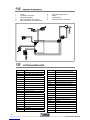
14 ELECTRICAL DIAGRAM
1 Fuse
2 Power switch
3 Circuit board
4 Counter micro-switch
5 Casing micro-switch
6 Lid micro-witch
7 Motor
8 Condenser
9 Tray micro-switch
9
8
7
6
5
4
3
2
1
19

15 LIST OF COMPONENTS
0504001A SX-50 CUÑAT REDUCER
0504002B 0.33CV, 225-50Hz MOTOR
0504003A TWO-PHASE 0.33CV 240/250V-50Hz
MOTOR
0504003B TWO-PHASE 0.33CV 115V-60Hz MOTOR
0504003C TWO-PHASE 0.33CV 220V-60Hz MOTOR
0504004A 16XL MOTOR PULLEY
0504005 REDUCER INPUT PULLEY (60XL037)
0504007 PIN WASHER AND REDUCER PIN
0504013 THRUST PANEL PIN
0504014-1 CUP GUIDE WITH INSERT
0504019 BELT 190XL 0.37
0504024 CUPS ALIGNMENT ADJUSTMENT PAD
0504026 SX-50 REDUCER OUTPUT SHAFT
0505010A FASTENING NUT WITH RAKED JOINT
0505010A-1 CUP NUT
0505010A-2 FASTENING NUT JOIN 20
0505016 PEEL EXTRACTION RUBBER RING
0506006/1 TRAY MICRO SPRING
0506007 SHORT MICROMETER
0506008 LONG MICROMETER
0506010 POWER CORD
0506014 ELECTRICAL PLUG WITH FUSES
0506015 BLACK BIPOLAR SWITCH
0506021 ZUMMITO PLATE BUSHING
0506027 PLASTIC CAP Ø17,3
0508013 RUBBER SUPPORT 85mm
10/21 CONDENSER 30μF (MOTOR 230V)
10/25 CONDENSER 100μF (MOTOR 115V)
10/28 CONDENSER 22μF (MOTOR 240V)
1011028 LEVER MICROSWITCH 60g.
1401A00 CASING UNIT
1401B00 CASING CLOSURE
1402001 FRONT
1402002 CUP GUIDE COVER
1402003 Z14 CASING
1402004 OUTER SIDE
1402005L LEFT INTERIOR SIDE
1402005R RIGHT INTERIOR SIDE
1402006 REAR
1402007A LOWER COVER
1402008 UPPER VENT
1402009 SIDE COVER
1402010 REAR SILKSCREENING
1402011 BLADE GUIDE COVER
1402014 RUBBER HOLE GROMMET
1402015 SUPLEMENT Z14 CUP GUIDE
1403001 HOPPER TRACK
1403002 FEEDER ACTUATOR
1403003 BASKET PINS
1403004 BASKET BUSHING
1403005 SEPARATOR 50-75
1403006 SEPARATOR 70-90
1403007 BASKET
1403008 DIVIDER
1403008-1 DIVIDER CILINDER
1403009 TONGUE
1403010 HOPPER SECTION
1403011 TONGUE SUPPORT
1403012 HOPPER BASKET
1404001 PINION
1404003 ROD
1404004 CUP GUIDE ELASTIC
1404005 CUP GUIDE BRACE
1404007 BRIDGE GUIDE
1404008 BLADE GUIDE
1404009 BRACE GUIDE
1404010 UPPER ROD PIN
1404011 TREAD PIN
1404013 CUP BRACE SUPPORT
1404019 CUP SLIDE BRIDGE
1404020 POLEY 14XL 0.50
1404021 BELT 190XL 0.50
1404024 MOTOR ANCHORING Z14-09
1404A00 THRUST UNIT
1404B00 BLADE SUPPORT UNIT
1404C00 COPIER UNIT
1405001 Z14 3mm FILTER
1405002 Z14 4mm FILTER
1405003 Z14 FILTER TRAY
1405004A CUP SHAFT
1405005 Z14 JUICE TRAY
1405006 Z14 LARGE CUP
1405007 Z14 LARGE BALL
1405008 Z14 MEDIUM CUP
1405009 Z14 MEDIUM BALL
1405010 Z14 SMALL CUP
1405011 Z14 SMALL BALL
1405012 Z14 BLADE
1405013 PIN WITH BASE
1405015 LOW-PASS FILTER
1405017 SUPLEMENT LEFT AXIS
1405018 SUPLEMENT RIGHT AXIS
1406001 CPU MOTHERBOARD
1406002 CPU 220/240V-50/60Hz
1406002A CPU 110V-50/60Hz
1406003 COUNTER MICRO SUPPORT
1406004 TRAY MICRO SUPPORT
1406006 CPU SILKSCREEN
1406007 TOP MICRO SUPPORT
1408001 Z14 TRAY
20
1404002A BRIDGE
La pagina sta caricando ...
La pagina sta caricando ...
La pagina sta caricando ...
La pagina sta caricando ...
La pagina sta caricando ...
La pagina sta caricando ...
La pagina sta caricando ...
La pagina sta caricando ...
La pagina sta caricando ...
La pagina sta caricando ...
La pagina sta caricando ...
La pagina sta caricando ...
La pagina sta caricando ...
La pagina sta caricando ...
La pagina sta caricando ...
La pagina sta caricando ...
La pagina sta caricando ...
La pagina sta caricando ...
La pagina sta caricando ...
La pagina sta caricando ...
La pagina sta caricando ...
La pagina sta caricando ...
La pagina sta caricando ...
La pagina sta caricando ...
La pagina sta caricando ...
La pagina sta caricando ...
La pagina sta caricando ...
La pagina sta caricando ...
La pagina sta caricando ...
La pagina sta caricando ...
La pagina sta caricando ...
La pagina sta caricando ...
La pagina sta caricando ...
La pagina sta caricando ...
La pagina sta caricando ...
La pagina sta caricando ...
La pagina sta caricando ...
La pagina sta caricando ...
La pagina sta caricando ...
La pagina sta caricando ...
La pagina sta caricando ...
La pagina sta caricando ...
La pagina sta caricando ...
La pagina sta caricando ...
La pagina sta caricando ...
La pagina sta caricando ...
La pagina sta caricando ...
La pagina sta caricando ...
La pagina sta caricando ...
La pagina sta caricando ...
La pagina sta caricando ...
La pagina sta caricando ...
La pagina sta caricando ...
La pagina sta caricando ...
La pagina sta caricando ...
La pagina sta caricando ...
La pagina sta caricando ...
La pagina sta caricando ...
La pagina sta caricando ...
La pagina sta caricando ...
La pagina sta caricando ...
La pagina sta caricando ...
La pagina sta caricando ...
La pagina sta caricando ...
La pagina sta caricando ...
La pagina sta caricando ...
La pagina sta caricando ...
La pagina sta caricando ...
La pagina sta caricando ...
La pagina sta caricando ...
La pagina sta caricando ...
La pagina sta caricando ...
La pagina sta caricando ...
La pagina sta caricando ...
-
 1
1
-
 2
2
-
 3
3
-
 4
4
-
 5
5
-
 6
6
-
 7
7
-
 8
8
-
 9
9
-
 10
10
-
 11
11
-
 12
12
-
 13
13
-
 14
14
-
 15
15
-
 16
16
-
 17
17
-
 18
18
-
 19
19
-
 20
20
-
 21
21
-
 22
22
-
 23
23
-
 24
24
-
 25
25
-
 26
26
-
 27
27
-
 28
28
-
 29
29
-
 30
30
-
 31
31
-
 32
32
-
 33
33
-
 34
34
-
 35
35
-
 36
36
-
 37
37
-
 38
38
-
 39
39
-
 40
40
-
 41
41
-
 42
42
-
 43
43
-
 44
44
-
 45
45
-
 46
46
-
 47
47
-
 48
48
-
 49
49
-
 50
50
-
 51
51
-
 52
52
-
 53
53
-
 54
54
-
 55
55
-
 56
56
-
 57
57
-
 58
58
-
 59
59
-
 60
60
-
 61
61
-
 62
62
-
 63
63
-
 64
64
-
 65
65
-
 66
66
-
 67
67
-
 68
68
-
 69
69
-
 70
70
-
 71
71
-
 72
72
-
 73
73
-
 74
74
-
 75
75
-
 76
76
-
 77
77
-
 78
78
-
 79
79
-
 80
80
-
 81
81
-
 82
82
-
 83
83
-
 84
84
-
 85
85
-
 86
86
-
 87
87
-
 88
88
-
 89
89
-
 90
90
-
 91
91
-
 92
92
-
 93
93
-
 94
94


in altre lingue
- français: Zummo Z14 nature Manuel utilisateur
- español: Zummo Z14 nature Manual de usuario
- Nederlands: Zummo Z14 nature Handleiding
- português: Zummo Z14 nature Manual do usuário
Altri documenti
-
 Vega 118440011 Manuale utente
-
Zumex Speed Pro Tank Podium Manuale utente
-
Cecilware Zumex Autoservicio Istruzioni per l'uso
-
Cecilware Zumex 100 Istruzioni per l'uso
-
 Zumex Essential Manuale utente
-
Ferm CSM1016 Manuale del proprietario
-
Ferm CSM1002 Manuale utente
-
BALAY 3VF705XA/60 Manuale utente
-
BALAY 3VS723BA/01 Manuale utente
-
BALAY 3VS775BA/27 Manuale utente

