Stageline STA-250 Manuale utente
- Categoria
- Amplificatore per strumenti musicali
- Tipo
- Manuale utente

STA-250 Bestellnummer 25.3220
ELECTRONICS FOR SPECIALISTS ELECTRONICS FOR SPECIALISTS ELECTRONICS FOR SPECIALISTS ELECTRONICS FOR SPECIALISTS
BEDIENUNGSANLEITUNG
INSTRUCTION MANUAL
MODE D’EMPLOI
ISTRUZIONI PER L’USO
MANUAL INSTRUCCIONES
INSTRUKCJA OBSŁUGI
VEILIGHEIDSVOORSCHRIFTEN
SIKKERHEDSOPLYSNINGER
SÄKERHETSFÖRESKRIFTER
TURVALLISUUDESTA
Stereo-PA-Verstärker
Stereo PA Amplifier

2
Deutsch . . . . . . . . . . . . . . Seite 4
English . . . . . . . . . . . . . . . Page 7
Français . . . . . . . . . . . . . . Page 10
Italiano . . . . . . . . . . . . . . Pagina 13
Español . . . . . . . . . . . . . . Página 16
Polski . . . . . . . . . . . . . . . . Strona 19
Nederlands . . . . . . . . . . . Pagina 22
Dansk . . . . . . . . . . . . . . . Sida 22
Svenska . . . . . . . . . . . . . . Sidan 23
Suomi . . . . . . . . . . . . . . . Sivulta 23
ELECTRONICS FOR SPECIALISTS ELECTRONICS FOR SPECIALISTS ELECTRONICS FOR SPECIALISTS ELECTRONICS FOR SPECIALISTS

3
123 421 5
6 7 8 9 10 11 12 13 10 9 8 7 6
810 17 18
a
b
c
d
14 15 16 17 18 19 20
Anschlussmöglichkeit
je Ausgang
Connecting possibility
per output
Betriebsart
Mode
Z je Lautsprecher
Z per speaker
PMIN je Lautsprecher
PMIN per speaker
+
-
STEREO, PARALLEL 4 Ω 700 W
STEREO, PARALLEL 8 Ω 500 W
BRIDGE 8 Ω 1200 W
+
-
+
-
STEREO, PARALLEL 8 Ω 350 W
STEREO, PARALLEL 16 Ω 250 W
BRIDGE 16 Ω 600 W
+
-
+
-
STEREO, PARALLEL 4 Ω 250 W
BRIDGE 4 Ω 600 W
BRIDGE 8 Ω 500 W
+
-
+
-
+
-
+
-
STEREO, PARALLEL 4 Ω 175 W
STEREO, PARALLEL 8 Ω 125 W
BRIDGE 8 Ω 300 W
e
f
g
k
h
i
j

4
Stereo-PA-Verstärker
Bitte lesen Sie diese Anleitung vor dem Betrieb
gründlich durch und heben Sie sie für ein
späteres Nachlesen auf. Auf der ausklappbaren
Seite 3 finden Sie alle beschriebenen Bedien-
elemente und Anschlüsse.
1 Übersicht der Bedienelemente
und Anschlüsse
1.1 Vorderseite
1Lautstärkeregler
jeweils für die Kanäle L-CH und R-CH
Hinweis: Im Parallel- und Brückenbetrieb ist
der Regler des Kanals R-CH ohne Funktion.
2Status-LEDs
jeweils für die Kanäle L-CH und R-CH
PROTECT
leuchtet, wenn die Schutzschaltung den
Lautsprecher vom Verstärker trennt: für
kurze Zeit nach dem Einschalten und bei
Überlastung/ Überhitzung des Verstärkers
LIMITER
leuchtet, wenn die Begrenzerschaltung aktiv
ist und zur Vermeidung von Übersteuerung
das Signal reduziert
SIGNAL/
-
20 dB/
-
10 dB
zeigen den Pegel des Ausgangssignals
3LC-Display zur Anzeige der Betriebsparame-
ter und Status (Kap. 1.3)
4Taste LOAD 4/ 8 OHM zur Wahl der Laut-
sprecherlast für die korrekte Berechnung der
Leistungsanzeige im Display (3) [ggf. mehr-
mals drücken]
5Netzschalter POWER
1.2 Rückseite
6Umschalter für den Einstellbereich der Filter-
frequenz des entsprechenden Reglers
CROSSOVER FREQ. (7) jeweils für die
Kanäle L-CH und R-CH:
„×1“ (Schalter ausgerastet):
45 – 960 Hz
„×10“ (Schalter hineingedrückt):
450 – 9600 Hz
7Regler CROSSOVER FREQ. für die Filterfre-
quenz jeweils für die Kanäle L-CH und R-CH
Hinweis: Im Parallel- und Brückenbetrieb ist
der Regler des Kanals R-CH ohne Funktion.
8Eingang als 6,3-mm-Klinkenbuchse, symme-
trisch beschaltet, zum Anschluss einer Sig-
nalquelle mit Line-Pegel jeweils für die
Kanäle L-CH und R-CH
Hinweis: Im Parallel- und Brückenbetrieb ist
der Eingang des Kanals R-CH ohne Funk-
tion.
9Wahlschalter für den Einsatz des Filters je -
weils für die Kanäle L-CH und R-CH
HIGH Hochpassfilter
BYPASS kein Filter
LOW Tiefpassfilter
10 Eingang als XLR-Buchse, alternativ zur Klin-
kenbuchse (8), jeweils für die Kanäle L-CH
und R-CH
Hinweis: Im Parallel- und Brückenbetrieb ist
der Eingang des Kanals R-CH ohne Funk-
tion.
11 Ein-/Ausschalter (ON/ OFF) LIMITER für die
automatische Pegelbegrenzung
12 Wahlschalter für die Betriebsart
STEREO / PARALLEL / BRIDGE (Kap. 6.1)
13 Schalter GROUNDLIFT zur Trennung von
Signalmasse und Gehäusemasse:
GND
Signalmasse mit Gehäusemasse verbunden
LIFT
Signalmasse und Gehäusemasse getrennt
(groundlift)
14 Schutzschalter zur Geräteabsicherung; zum
Zurücksetzen des ausgelösten Schalters den
Knopf bei ausgeschaltetem Gerät hineindrü-
cken
15 Netzkabel zum Anschluss an eine Steckdose
(230 V~/50 Hz)
16 Lautsprecherbuchse R-CH
17 Lautsprecherausgang R-CH als Schraub-
klemmen, alternativ zur Lautsprecherbuchse
(16)
18 Lautsprecherausgang L-CH als Schraub-
klemmen, alternativ zur Lautsprecherbuchse
(19)
19 Lautsprecherbuchse L-CH
20 Lautsprecherbuchse BRIDGE für den Brü-
ckenbetrieb
1.3 Display
Normale Anzeige während des Betriebs (Abb. 4)
aAusgangsleistung beider Ausgänge, be -
rechnet nach der gemessenen Ausgangs-
spannung und der gewählten Last impedanz
[Taste LOAD 4/ 8 OHM (4)]
Hinweis: Die Berechnung gilt nicht im Brü-
ckenbetrieb.
bAnzeige CLIP ON/ OFF für beide Ausgänge;
wird CLIP ON angezeigt, ist der Verstärker-
eingang übersteuert. In diesem Fall den Ein-
gangspegel mit dem entsprechenden Regler
(1) reduzieren.
cAnzeige PROT ON/ OFF (= PROTECTION,
Kap. 1.1, Punkt 2, Status-LED PROTECT)
dTemperatur an den Leistungstransistoren
beider Kanäle
evertikale Balkenanzeige für die Ausgangs-
signale beider Kanäle
Anzeige für einige Sekunden nach der Betäti-
gung eines Lautstärkereglers (1), des Schalters
LIMITER (11) oder des Schalters für die
Betriebsart (12) [Abb. 5]
fAnzeige STEREO/ PARALL/ BRIDGE der ge -
wählten Betriebsart
gKontrolle für den Schalter LIMITER (11)
LIMT ON = Limiter eingeschaltet
LIMT OFF = Limiter ausgeschaltet
hAnzeige ATTEN (attenuation) für die Ab -
schwächung der Eingangssignale zeigt die
Stellung der Lautstärkeregler (1) numerisch
(i) und als vertikale Balken (j)
Anzeige für einige Sekunden nach der Betäti-
gung der Taste LOAD 4/ 8 OHM (4) [Abb. 6]
kAnzeige der gewählten Lastimpedanz für die
Berechnung der angezeigten Ausgangsleis-
tung (a)
2 Hinweise für den
sicheren Gebrauch
Das Gerät entspricht allen relevanten Richt linien
der EU und ist deshalb mit gekennzeichnet.
Beachten Sie auch unbedingt die folgenden
Punkte:
Das Gerät ist nur zur Verwendung im Innen -
bereich geeignet. Schützen Sie es vor Tropf-
und Spritzwas ser, hoher Luftfeuchtigkeit und
Hitze (zulässiger Einsatztemperaturbereich
0 – 40 °C).
Stellen Sie keine mit Flüssigkeit gefüllten Ge -
fäße, z. B. Trinkgläser, auf das Gerät.
Die im Gerät entstehende Wärme muss durch
Luftzirkulation abgegeben werden. Decken
Sie darum die Lüftungsöffnungen nicht ab.
Nehmen Sie das Gerät nicht in Betrieb und
ziehen Sie sofort den Netzstecker aus der
Steckdose,
1. wenn sichtbare Schäden am Gerät oder am
Netzkabel vorhanden sind,
2. wenn nach einem Sturz oder Ähnlichem der
Verdacht auf einen Defekt besteht,
3. wenn Funktionsstörungen auftreten.
Geben Sie das Gerät in jedem Fall zur Repa-
ratur in eine Fachwerkstatt.
Ein beschädigtes Netzkabel darf nur durch
eine Fachwerkstatt ersetzt werden.
Ziehen Sie den Netzstecker nie am Kabel aus
der Steckdose, fassen Sie immer am Stecker
an.
Verwenden Sie für die Reinigung nur ein tro-
ckenes, weiches Tuch, niemals Wasser oder
Chemikalien.
Wird das Gerät zweckentfremdet, nicht richtig
angeschlossen, falsch be dient oder nicht
fachgerecht repariert, kann keine Haftung für
daraus resultierende Sach- oder Personen-
schäden und keine Garantie für das Gerät
übernommen werden.
3 Einsatzmöglichkeiten
Dieser PA-Stereo-Verstärker ist speziell für den
Einsatz auf der Bühne und in der Diskothek kon-
zipiert. Er kann im Stereobetrieb, im Mono-
Parallelbetrieb oder im Mono-Brückenbetrieb
genutzt werden. Beide Kanäle verfügen über ein
durchstimmbares Filter mit weitem Einstellbe-
reich. Die Filter können als Frequenzweiche
genutzt werden, um den Verstärkerkanal z. B.
nur für einen Subwoofer oder nur für den Hoch-
tonbereich einzusetzen. Umfangreiche Schutz-
schaltungen schützen den Verstärker und die
angeschlossenen Lautsprecher. Zwei leistungs-
starke, temperaturgeregelte Lüfter sorgen für die
nötige Kühlung des Verstärkers.
Soll das Gerät endgültig aus dem Be -
trieb genommen werden, übergeben
Sie es zur umweltgerechten Entsor-
gung einem örtlichen Recyclingbetrieb.
WARNUNG Das Gerät wird mit lebensge fähr -
licher Netzspannung versorgt.
Nehmen Sie deshalb niemals
selbst Eingriffe am Gerät vor und
stecken Sie nichts in die Lüftungs-
schlitze. Es besteht die Gefahr
eines elektrischen Schlages.
Deutsch

4 Aufstellen des Verstärkers
Der Verstärker ist für den Einschub in ein Rack
für Geräte mit einer Breite von 482 mm (19″)
vorgesehen, kann aber auch als Tischgerät ver-
wendet werden. In jedem Fall muss Luft unge-
hindert durch alle Lüftungsöffnungen strömen
können, damit eine ausreichende Kühlung des
Verstärkers gewährleistet ist.
4.1 Rackeinbau
Für die Rackmontage werden 2 HE (Höhenein-
heiten) = 89 mm benötigt. Die vom Verstärker
rückseitig ausgeblasene, erhitzte Luft muss aus
dem Rack austreten können. Anderenfalls
kommt es im Rack zu einem Hitzestau, wodurch
nicht nur der Verstärker, sondern auch andere
Geräte im Rack beschädigt werden können. Bei
unzureichendem Wärmeabfluss in das Rack
eine Lüftereinheit einsetzen.
Damit das Rack nicht kopflastig wird, muss
der Verstärker im unteren Bereich des Racks
eingeschoben werden. Für eine sichere Befesti-
gung reicht die Frontplatte allein nicht aus.
Zusätzlich muss das Gerät an der Rückseite
befestigt oder über Seitenschienen oder eine
Bodenplatte gehalten werden.
5 Anschlüsse herstellen
Vor dem Anschließen von Geräten oder dem
Ändern bestehender Anschlüsse den Verstärker
und die anzuschließenden Geräte ausschalten.
1) An die Klinken-Buchsen INPUTS (8) oder die
XLR-Buchsen (10) den Ausgang eines Vor-
verstärkers oder eines Mischpults anschlie-
ßen. Die Buchsen sind für symmetrische Sig-
nale beschaltet; die Kontaktbelegung ist in
Abbildung 2 dargestellt. Für den Anschluss
von Quellen mit asymmetrischen Signalen
können 2-polige Klinkenstecker verwendet
werden oder Adapter, bei denen die XLR-
Kontakte 1 und 3 gebrückt sind.
Das Eingangssignal sollte Line-Pegel auf-
weisen. Für eine Vollaussteuerung des Ver-
stärkers ist ein Eingangssignal von mindes-
tens 1 V erforderlich.
Für den Brücken- oder Parallelbetrieb nur
den Eingang des linken Kanals L-CH an -
schließen.
Da die XLR-Buchsen und die Klinkenbuch-
sen desselben Eingangs jeweils direkt ver-
bunden sind, können sie auch zum Weiterlei-
ten des Signals z. B. zu einem zusätzlichen
Verstärker genutzt werden.
2) Die größte Ausgangsleistung wird im Stereo-
betrieb und im Parallelbetrieb beim An -
schluss von 4-Ω-Lautsprechern (minimal
zulässige Lastimpedanz) erreicht. Es können
auch 8-Ω-Laut sprecher angeschlossen wer-
den, was die Ausgangsleis tung aber etwas
verringert. Im Brückenbetrieb wird die größte
Ausgangsleistung mit einem 8-Ω-Laut -
sprecher (minimal zulässige Lastimpedanz
im Brückenbetrieb) erreicht. Die erforderliche
Nenn belastbarkeit (PMIN) der Lautsprecher
ist in der Tabelle Abb. 3 aufgeführt.
Für den Stereo- oder Parallelbetrieb die
Lautsprecher an die Lautsprecherbuchsen
(16, 19), Kontaktbelegung des Steckers siehe
Abb. 2, oder an die Schraub klemmen (17, 18)
an schließen.
Einen Lautsprecherstecker nach dem Ein-
stecken in die Buchse nach rechts drehen, bis
er einrastet. Zum späteren Herausziehen den
Sicherungsriegel am Stecker zurückziehen
und den Stecker nach links drehen.
Werden die Schraubklemmen genutzt,
darauf achten, dass die Kabelenden nicht zu
weit abisoliert sind und keine blanken Drähte
herausragen (Berührungs- und Kurzschluss-
gefahr).
Beim Anschluss der Lautsprecher ist auf
die gleiche Polung aller Lautsprecher zu ach-
ten.
Für den Brückenbetrieb den Pluskontakt
des Lautsprechers mit der Plusklemme (18)
des linken Ausgangs L-CH verbinden und
den Minuskontakt des Lautsprechers mit der
Plusklemme des rechten Ausgangs R-CH
(17). (Die Plusklemme des rechten Ausgangs
wird durch die Signalinvertierung im Brücken-
betrieb zum Minus anschluss für den Laut-
sprecher.) Der Lautsprecher kann alternativ
auch an die Lautsprecherbuchse BRIDGE
(20) angeschlossen werden [Kontaktbele-
gung des Steckers Abb. 2].
In der Tabelle Abb. 3 sind auch Anschluss-
möglichkeiten für mehrere Lautsprecher an
einem Ausgang aufgeführt. Dazu ist jeweils
angegeben, welche Nennbelastbarkeit (PMIN)
jeder Lautsprecher bei entsprechender Impe-
danz (Z) mindestens haben muss. Beim
Zusammenschalten von mehreren Lautspre-
chern ist besonders auf die richtige Verbin-
dung der Plus- und Minusanschlüsse zu ach-
ten.
Wichtig: Die Gesamtimpedanz an jedem
Ausgang darf im Stereo- und Parallelbetrieb
4 Ω, im Brückenbetrieb 8 Ω nicht unterschrei-
ten!
3) Den Stecker des Netzkabels (15) in eine
Steckdose (230 V~/50 Hz) stecken.
6 Bedienung
6.1 Betriebsart wählen
Mit dem Schalter STEREO/ PARALLEL/ BRIDGE
(12) die gewünschte Betriebsart wählen.
Stereobetrieb – „STEREO“
Im Stereobetrieb werden beide Kanäle unab-
hängig voneinander betrieben.
Parallelbetrieb – „PARALL“
Das Eingangssignal wird intern vom linken
Kanal zusätzlich auf den rechten Kanal geschal-
tet. Ein Signal am rechten Eingang wird ignoriert.
Die Lautstärkeeinstellung erfolgt für beide Aus-
gänge gemeinsam mit dem linken Regler. Auch
die Filtereinstellung (Kap. 6.2) erfolgt über
die Schalter und den Regler des Eingangs L-CH
für beide Kanäle gemeinsam.
Brückenbetrieb – „BRIDGE“
Der Brückenbetrieb dient dazu, an einem Laut-
sprecher eine größere Leistung zu erhalten.
Dazu werden beide Verstärkerkanäle zu einem
Monoverstärker kombiniert: Das Eingangssignal
am linken Kanal wird zusätzlich invertiert auf den
rechten Kanal geschaltet. Dadurch verdoppelt
sich die Spannung am Ausgang, wenn der Laut-
sprecher, wie in Kap. 5 beschrieben, für den Brü-
ckenbetrieb angeschlossen ist. Ein Signal am
rechten Eingang wird ignoriert. Die Lautstärke-
einstellung erfolgt mit dem linken Regler und die
Einstellung des Filters (Kap. 6.2) am Eingang
L-CH.
6.2 Filter
Das eingebaute Filter kann als Frequenzweiche
für 2-Wege-Lautsprechersysteme (z. B. Sub-
woofer / Satellite) verwendet werden. Mit dem
Schalter HIGH/ BYPASS/ LOW (9) die dem
angeschlossenen Lautsprecher entsprechende
Funktion wählen.
Position LOW: Tiefpassfilter
(18 dB / Oktave)
Position HIGH: Hochpassfilter
(18 dB / Oktave)
Position BYPASS: kein Filter
Mit dem Regler CROSSOVER FREQ. (7) die
Grenzfrequenz des Filters einstellen. Über den
darunterliegenden Schalter (6) den Einstellbe-
reich wählen. Zur Vermeidung von Schaltgeräu-
schen diesen Schalter nur bei ausgeschaltetem
Filter [Schiebeschalter (9) in Position BYPASS]
betätigen.
Schalter ausgerastet „×1“: 45 – 960 Hz
Schalter hineingedrückt „×10“: 450 – 9600 Hz
Bei der Frequenzeinstellung den Übertragungs-
bereich des angeschlossenen Lautsprechers
berücksichtigen. Der Betrieb eines Lautspre-
chers außerhalb seines Übertragungsbereichs
kann zu Verzerrungen und zur Überlastung des
Lautsprechers führen.
6.3 Ein- /Ausschalten
Zur Vermeidung von lauten Schaltgeräuschen
den Endverstärker in einer Verstärkeranlage
immer nach allen anderen Geräten einschalten
und ihn nach dem Betrieb als erstes Gerät wie-
der ausschalten. Vor dem ersten Einschalten die
Lautstärkeregler (1) ganz nach links auf „MIN“
drehen.
Den Verstärker mit dem Schalter POWER
(5) einschalten. Das Display (3) zeigt nach der
Begrüßung zunächst kurz die Einstellungen der
Betriebsart, des Limiters und der Eingangsab-
schwächung (Abb. 5) und wechselt dann auf die
normale Betriebsanzeige (Abb. 4). Nach dem
Einschalten leuchten für kurze Zeit die LEDs
PROTECT und LIMITER (2). In dieser Zeit ist die
Einschaltverzögerung zum Schutz der Lautspre-
cher aktiv.
6.4 Pegel einstellen
Den Ausgang des Mischpultes oder Vorverstär-
kers auf seinen Nennpegel (0 dB) oder das
größte unverzerrte Ausgangssignal aussteuern.
Die Regler (1) so weit aufdrehen, bis die maxi-
mal ge wünschte Lautstärke erreicht ist. Die
Abschwächung „ATTEN“ des Eingangssignals
durch die Regler wird im Display (3) sowohl
numerisch (i) als auch grafisch (j) einige Sekun-
den lang nach dem Ändern der Einstellung
angezeigt. Dann wechselt das Display wieder
auf die Normalanzeige (Abb. 4). Die LEDs SIG-
NAL,
-
20 dB und
-
10 dB (2) und ein vertikaler
Balken (e) im Display zeigen den Ausgangspe-
gel an.
Zeigt das Display CLIP ON, ist der Eingang
übersteuert. Leuchten die LIMITER-LEDs, ist die
Begrenzerschaltung aktiv und verhindert die
Übersteuerung des Verstärkers (Kap. 7). In
beiden Fällen den entsprechenden Regler (1)
zu rückdrehen.
6.5 Leistungsanzeige
Die normale Anzeige während des Betriebs
(Abb. 4) zeigt in der ersten Zeile (a) die Aus-
gangsleistung beider Lautsprecherausgänge.
Dabei handelt es sich um einen Wert, der nach
der gemessenen Ausgangsspannung und einer
angenommenen Last impedanz berechnet wurde.
VORSICHT Stellen Sie die Lautstärke am Ver-
stärker nie sehr hoch ein. Hohe
Lautstärken können auf Dauer
das Gehör schädigen! Das Ohr
gewöhnt sich an hohe Lautstärken
und empfindet sie nach einiger
Zeit als nicht mehr so hoch.
Darum erhöhen Sie eine hohe
Lautstärke nach der Gewöhnung
nicht weiter.
5
Deutsch

Die vorgegebene Lastimpedanz ist nach dem
Einschalten des Verstärkers immer 8 Ω.
Sind 4-Ω-Lautsprecher angeschlossen, für
eine Anpassung der Berechnung die Taste
LOAD 4/ 8 OHM (4) drücken. Im Display wird
jetzt OUT 4Ω (k) angezeigt und die Leistung für
eine Lastimpedanz von 4 Ω berechnet. Zum
Zurückschalten die Taste wiederholt drücken,
bis OUT 8Ω angezeigt wird. Einige Sekunden
nach dem letzten Tastendruck schaltet das Dis-
play wieder auf die Normalanzeige um.
Hinweis: Die angezeigte Leistung gilt nicht im
Brückenbetrieb.
6.6 Groundlift-Schalter
Ist ohne ein Musiksignal ein störendes Brummen
zu hören, kann eine Masseschleife die Ursache
sein. Masseschleifen können entstehen, wenn
zwei Geräte sowohl über die Signalmasse als
auch über den Schutzleiter der Stromversor-
gung oder eine leitende Verbindung der
Gehäuse im Rack Kontakt haben. Um die so ent-
standene Masseschleife aufzutrennen, den
Schalter GROUNDLIFT (13) in die Position LIFT
stellen.
7 Schutzschaltungen
Die Schutzschaltungen sollen Beschädigungen
der Lautsprecher und des Verstärkers verhin-
dern. Der eingebaute Pegelbegrenzer (Limiter)
regelt das Eingangssignal zurück, wenn der
Grenzpegel am Ausgang erreicht wird. Dadurch
lassen sich bei Übersteuerung des Verstärkers
Verzerrungen ver mei den, die die Lautsprecher
schädigen könnten. Mit dem Schalter LIMITER
(11) kann diese Funktion ein- und ausgeschaltet
werden [Anzeige LIMT ON bzw. LIMT OFF (g)].
Ist der Begrenzer aktiv, leuchtet die LIMITER-
LED (2) des entsprechenden Kanals.
Durch eine zusätzliche Schutzschaltung
werden die Lautsprecher vom Ausgang des
betroffenen Kanals getrennt. Ist sie aktiv, leuch-
tet die entsprechende rote PROTECT-LED (2):
1. für kurze Zeit nach dem Einschalten (Ein-
schaltverzögerung)
2. bei Überlastung/ Überhitzung, dabei wechselt
zusätzlich im Display (3) die Anzeige PROT
OFF (c) zu PROT ON
Nach dem Abkühlen nimmt der Verstärkerka-
nal selbstständig wieder den Betrieb auf.
Im normalen Betrieb wird im Display die Tempe-
ratur an den Leistungstransistoren für beide
Kanäle getrennt angezeigt (d). Bei höheren
Temperaturen sorgt die Lüfterregelung dafür,
dass der Lüfter des betroffenen Kanals mit einer
höheren Geschwindigkeit läuft.
Wenn eine PROTECT-LED nach dem Ein-
schalten oder nach dem Abkühlen nach einer
Überlastung nicht erlischt oder wenn der
Schutzschalter (14) ausgelöst hat, muss der
Verstärker ausgeschaltet und die Fehlerursache
behoben werden. Wenn erforderlich, bei aus-
geschaltetem Gerät den Schutzschalter durch
Hineindrücken wieder zurücksetzen.
6
Deutsch
Diese Bedienungsanleitung ist urheberrechtlich für MONACOR ®INTERNATIONAL GmbH & Co. KG
geschützt. Eine Reproduktion für eigene kommerzielle Zwecke – auch auszugsweise – ist untersagt.
Sinus-Ausgangsleistung
Stereo, Parallel an 4 Ω
Stereo, Parallel an 8 Ω
Brückenbetrieb an 8 Ω
2 × 700 W
2 × 500 W
1200 W
Eingangsempfindlichkeit für
Nennleistung an 8 Ω
Eingangsimpedanz
1V
20 kΩ
Frequenzbereich 20 – 20 000 Hz
Hochpassfilter/ Tiefpassfilter 45 – 9600 Hz, 18 dB/ Oktave
Kanaltrennung
Störabstand
> 35 dB
> 78 dB
Klirrfaktor < 0,1 %
Anschlüsse
Eingänge
Ausgänge
XLR- und 6,3-mm-Klinkenbuchsen, symmetrisch
Schraubklemmen und Lautsprecherbuchsen
(Speakon-kompatibel)
Einsatztemperatur 0 – 40 °C
Stromversorgung
max. Leistungsaufnahme
230 V~/ 50 Hz
2900 VA
Abmessungen (B × H × T)
Gewicht
482 × 100 × 455 mm,
2HE
19,1 kg
8 Technische Daten
8.1 Blockschaltbild
Änderungen vorbehalten.

Stereo PA amplifier
Please read these operating instructions careful-
ly prior to operation and keep them for later refer -
ence. All operating elements and connections
described can be found on the fold-out page 3.
1 Operating Elements and
Connections
1.1 Front panel
1Volume control
each for the channels L-CH and R-CH
Note: In parallel operation and bridge opera-
tion the control of the channel R-CH has no
function.
2Status LEDs
each for the channels L-CH and R-CH
PROTECT
lights up when the protective circuit discon-
nects the speaker from the amplifier: for a
short time after switching-on and in case of
overload/overheating of the amplifier
LIMITER
lights up when the limiter circuit is active and
reduces the signal to prevent overload
SIGNAL/
-
20 dB/
-
10 dB
show the level of the output signal
3LC display to show the operating parameters
and status (chapter 1.3)
4Button LOAD 4/ 8 OHM to select the speaker
load for the correct calculation of the power
indication on the display (3) [if required, press
several times]
5Mains switch POWER
1.2 Rear panel
6Selector switch for the adjusting range of the
filter frequency of the corresponding control
CROSSOVER FREQ. (7), each for the chan-
nels L-CH and R-CH:
“×1” (switch disengaged):
45 – 960 Hz
“×10” (switch pressed down):
450 – 9600 Hz
7Control CROSSOVER FREQ. for the filter
frequency, each for the channels L-CH and
R-CH
Note: In parallel operation and bridge opera-
tion the control of the channel R-CH has no
function.
8Input as a 6.3 mm jack, balanced, for con-
nection of a signal source with line level, each
for the channels L-CH and R-CH
Note: In parallel operation and bridge opera-
tion the input of the channel R-CH has no
function.
9Selector switch for the use of the filter, each
for the channels L-CH and R-CH
HIGH high pass filter
BYPASS no filter
LOW low pass filter
10 Input as an XLR jack, alternatively to the
6.3 mm jack (8), each for the channels L-CH
and R-CH
Note: In parallel operation and bridge opera-
tion the input of the channel R-CH has no
function.
11 ON / OFF switch LIMITER for the automatic
level limitation
12 Selector switch for the operating mode
STEREO / PARALLEL / BRIDGE
(chapter 6.1)
13 Switch GROUNDLIFT to separate the signal
ground from the housing ground:
GND
signal ground and housing ground are con-
nected
LIFT
signal ground and housing ground are sepa-
rated (groundlift)
14 Circuit breaker to protect the unit; to reset the
released switch, press down the button with
the unit switched off
15 Mains cable for connection to a socket
(230 V~/50 Hz)
16 Speaker jack R-CH
17 Speaker output R-CH as screw terminals, as
an alternative to the speaker jack (16)
18 Speaker output L-CH as screw terminals, as
an alternative to the speaker jack (19)
19 Speaker jack L-CH
20 Speaker jack BRIDGE for the bridge opera-
tion
1.3 Display
Standard indication during operation (fig. 4)
aoutput power of both outputs, calculated
according to the output voltage measured
and the load impedance selected [button
LOAD 4/ 8 OHM (4)]
Note: The calculation is not effective in
bridge operation.
bCLIP ON/ OFF for both outputs; if CLIP ON is
shown, the amplifier input is overloaded. In
this case reduce the input level with the cor-
responding control (1).
cPROT ON/ OFF (= PROTECTION, chapter
1.1, item 2, status LED PROTECT)
dtemperature at the power transistors of both
channels
evertical bargraph indication for the output sig-
nals of both channels
Indication for a few seconds after actuating a vol-
ume control (1), the switch LIMITER (11) or the
switch for the operating mode (12) [fig. 5]
fSTEREO/ PARALL/ BRIDGE of the selected
operating mode
gcheck for the switch LIMITER (11)
LIMT ON = limiter switched on
LIMT OFF = limiter switched off
hATTEN (attenuation) for attenuation of the
input signals shows the position of the vol-
ume controls (1) numerically (i) and as a ver-
tical bar (j)
Indication for a few seconds after actuating the
button LOAD 4/ 8 OHM (4) [fig. 6]
kselected load impedance for the calculation
of the output power shown (a)
2 Safety Notes
The unit corresponds to all relevant directives of
the EU and is therefore marked with .
It is essential to observe the following items:
The unit is suitable for indoor use only. Protect
it against dripping water and splash water,
high air humidity, and heat (admissible ambi-
ent temperature range 0 – 40 °C).
Do not place any vessels filled with liquid, e. g.
drinking glasses, on the unit.
The heat being generated in the unit must be
carried off by air circulation. Therefore, the air
vents at the housing must not be covered.
Do not set the unit into operation, and imme-
diately disconnect the mains plug from the
mains socket if
1. there is visible damage to the unit or to the
mains cable,
2. a defect might have occurred after a drop or
similar accident,
3. malfunctions occur.
The unit must in any case be repaired by
skilled personnel.
A damaged mains cable must only be re -
placed by skilled personnel.
Never pull the mains cable to disconnect the
mains plug from the mains socket, always
seize the plug.
For cleaning only use a dry, soft cloth, never
use chemicals or water.
No guarantee claims for the unit and no liabil-
ity for any resulting personal damage or mate-
rial damage will be accepted if the unit is used
for other purposes than originally intended, if it
is not correctly connected or operated, or not
repaired in an expert way.
Important for U. K. Customers!
The wires in this mains lead are coloured in
accordance with the following code:
green/yellow = earth
blue = neutral
brown = live
As the colours of the wires in the mains lead of
this appliance may not correspond with the
coloured markings identifying the terminals in
your plug, proceed as follows:
1. The wire which is coloured green and yel-
low must be connected to the terminal in the
plug which is marked with the letter E or by
the earth symbol , or coloured green or
green and yellow.
2. The wire which is coloured blue must be
connected to the terminal which is marked
with the letter N or coloured black.
3. The wire which is coloured brown must be
connected to the terminal which is marked
with the letter L or coloured red.
Warning – This appliance must be earthed.
If the unit is to be put out of operation
definitively, take it to a local recycling
plant for a disposal which will not be
harmful to the environment.
WARNING The unit is supplied with haz-
ardous mains voltage. Leave serv-
icing to skilled personnel only and
do not insert anything through the
air vents! This may cause an elec-
tric shock hazard.
7
English

3 Applications
This PA stereo amplifier is especially designed
for applications on stage and in the discotheque.
It can be used in stereo operation, in mono par-
allel operation or in mono bridge operation. Both
channels have a tunable filter with a wide adjust-
ing range. The filters can be used as a crossover
network to use the amplifier channel e. g. for a
subwoofer only or for the high range only. Exten-
sive protective circuits protect the amplifier and
the speakers connected. Two powerful, temper-
ature-controlled fans provide the necessary
cooling of the amplifier.
4 Placing the Amplifier
The amplifier is provided for insertion into a rack
for units with a width of 482 mm (19″), but it can
also be used as a tabletop unit. In each case air
must be allowed to flow freely through all venti-
lation slots so that a sufficient cooling of the
amplifier is ensured.
4.1 Rack installation
For rack mounting 2 rs (rack spaces) = 89 mm
are required. The heated air blown out by the
amplifier at the rear must be able to dissipate
from the rack, otherwise a heat accumulation will
occur in the rack which may not only damage the
amplifier but also other units in the rack. In case
the heat is not dissipated sufficiently, a fan unit
has to be inserted into the rack.
To prevent top-heaviness of the rack, the
amplifier must be inserted in the lower part of the
rack. To ensure a safe fixing, the front panel
alone is not sufficient. In addition, the unit must
be fastened at the rear side or be supported by
means of lateral rails or a bottom plate.
5 Connections
Prior to connecting units or changing existing
connections, switch off the amplifier and the
units to be connected.
1) Connect the output of a preamplifier or a
mixer to the 6.3 mm jacks INPUTS (8) or the
XLR jacks (10). The jacks are designed for
balanced signals; the pin configuration is
shown in fig. 2. For connection of sources
with unbalanced signals 2-pole 6.3 mm plugs
may be used or adapters with the XLR con-
tacts 1 and 3 bridged.
The input signal should have line level. For
rated power of the amplifier an input signal of
1 V is required as a minimum.
For bridge operation or parallel operation
only connect the input of the left channel
L-CH.
As the XLR jacks and the 6.3 mm jacks of
the same input are directly connected in each
case, they can also be used for passing on
the signal e. g. to an additional amplifier.
2) The maximum output power is reached in
stereo operation and in parallel operation
when connecting 4 Ω speakers (minimum
admissible load impedance). It is also possi-
ble to connect 8 Ω speakers, however, in this
case the output power will slightly be
decreased. In bridge operation the maximum
output power will be reached with an 8 Ω
speaker (minimum admissible load imped-
ance in bridge operation). The required
power rating (PMIN) of the speakers is listed in
the table fig. 3.
For stereo operation or parallel opera-
tion connect the speakers to the speaker
jacks (16, 19), pin configuration of the plug
see fig. 2, or to the screw terminals (17, 18).
After inserting a speaker plug into the jack,
turn the plug clockwise until it locks into
place. For removing it later, retract the latch
lock at the plug and turn the plug counter-
clockwise.
If the screw terminals are used, ensure
that the cable ends are not stripped too far
and that no bare wires protrude (hazard of
contact and short circuit).
When connecting the speakers, pay atten-
tion to the same polarity of all speakers.
For bridge operation connect the positive
pole of the speaker to the positive terminal
(18) of the left output L-CH and the negative
pole of the speaker to the positive terminal of
the right output R-CH (17). (By signal inver-
sion in bridge operation, the positive terminal
of the right output becomes the negative con-
nection for the speaker.) The speaker can
alternatively also be connected to the
speaker jack BRIDGE (20) [pin configuration
of the plug fig. 2].
Table fig. 3 also shows possibilities of con-
nection for several speakers to one output. In
each case it is stated which power rating
(PMIN) each speaker must have as a mini-
mum with the corresponding impedance (Z).
When interconnecting several speakers, spe-
cial attention has to be paid to the correct
connection of the positive and negative ter-
minals.
Important: The total impedance at each out-
put must not fall below 4 Ω in stereo operation
and parallel operation and must not fall below
8 Ω in bridge operation!
3) Connect the plug of the mains cable (15) to a
socket (230 V~/50 Hz).
6 Operation
6.1 Selecting the operating mode
Select the desired operating mode with the
switch STEREO/ PARALLEL/ BRIDGE (12).
Stereo operation – “STEREO”
In stereo operation, both channels are operated
independently of each other.
Parallel operation – “PARALL”
The input signal is internally switched from the
left channel to the right channel in addition. A
signal at the right input is ignored. The volume is
adjusted for both outputs together with the left
control. Also the filter is adjusted (chapter
6.2) via the switches and the control of the input
L-CH for both channels together.
Bridge operation – “BRIDGE”
The bridge operation serves to obtain a higher
power at one speaker. For this purpose both
amplifier channels are combined to a mono
amplifier: The input signal at the left channel is
additionally sent to the right channel in an
inverted way. Thus, the voltage at the output is
doubled if the speaker is connected for bridge
operation, as described in chapter 5. A signal at
the right input is ignored. The volume is adjusted
with the left control and the filter is adjusted at
the input L-CH (chapter 6.2).
6.2 Filter
The integrated filter can be used as a crossover
network for 2-way speaker systems (e. g. sub-
woofer / satellite). Select the function correspon-
ding to the connected speaker with the switch
HIGH / BYPASS / LOW (9).
Position LOW: low pass filter
(18 dB / octave)
Position HIGH: high pass filter
(18 dB / octave)
Position BYPASS: no filter
Adjust the cut-off frequency of the filter with the
control CROSSOVER FREQ. (7). Select the
adjusting range with the switch (6) below it. To
prevent switching noise, only actuate this switch
with the filter switched off [sliding switch (9) in
position BYPASS].
Switch released “×1”: 45 – 960 Hz
Switch pressed down “×10”: 450 – 9600 Hz
When adjusting the frequency, consider the fre-
quency response of the connected speaker. The
operation of a speaker outside its frequency
range may lead to distortions and overload of the
speaker.
6.3 Switching on/off
To prevent loud switching noise always switch
on the power amplifier in an amplifier system
after all other units and switch it off as the first
unit after operation. Prior to the first switching on,
turn the volume controls (1) to the left stop “MIN”.
Switch on the amplifier with the switch
POWER (5). After the welcome, first the display
(3) shortly shows the adjustments of the operat-
ing mode, the limiter and the input attenuation
(fig. 5) and then changes to the standard operat-
ing indication (fig. 4). After switching-on, the
LEDs PROTECT and LIMITER (2) light up for a
short time. During this time the switch-on delay
for the protection of the speakers is active.
6.4 Adjusting the level
Control the output of the mixer or preamplifier to
its rated level (0 dB) or the highest undistorted
output signal. Turn up the controls (1) so far until
the maximum desired volume is reached. The
attenuation “ATTEN” of the input signal by the
controls is shown on the display (3) both numer-
ically (i) and graphically (j) for a few seconds
after changing the adjustment. Then the display
is changed to the standard indication again (fig.
4). The LEDs SIGNAL,
-
20 dB and
-
10 dB (2)
and a vertical bar (e) on the display show the
output level.
If the display shows CLIP ON, the input is
overloaded. If the LIMITER LEDs light up, the
limiter circuit is active and prevents the overload
of the amplifier (chapter 7). In both cases turn
back the corresponding control (1).
6.5 Power indication
The standard indication during operation (fig. 4)
shows the output power of both speaker outputs
in the first line (a). This value has been calcu-
lated according to the output voltage measured
CAUTION Never adjust the amplifier to a
very high volume. Permanent high
volumes may damage your hear-
ing! The human ear will get accus-
tomed to high volumes which do
not seem to be that high any more
after some time. Therefore, do not
further increase a high volume
after getting used to it.
8
English

9
English
All rights reserved by MONACOR ®INTERNATIONAL GmbH & Co. KG. No part of this instruction
manual may be reproduced in any form or by any means for any commercial use.
RMS output power
stereo, parallel at 4 Ω
stereo, parallel at 8 Ω
bridge operation 8 Ω
2 × 700 W
2 × 500 W
1200 W
Input sensitivity for
rated power at 8 Ω
Input impedance
1V
20 kΩ
Frequency range 20 – 20 000 Hz
High pass filter / low pass filter 45 – 9600 Hz, 18 dB/ octave
Channel separation
S / N ratio
> 35 dB
> 78 dB
THD < 0.1 %
Connections
inputs
outputs
XLR and 6.3 mm jacks, balanced
screw terminals and speaker jacks
(Speakon compatible)
Ambient temperature 0 – 40 °C
Power supply
Max. power consumption
230 V~/ 50 Hz
2900 VA
Dimensions (W × H × D)
Weight
482 × 100 × 455 mm,
2RS
19.1 kg
8 Specifications
8.1 Block diagram
Subject to technical modification.
and a load impedance assumed. The specified
load impedance is always 8 Ω after switching on
the amplifier.
If 4 Ω speakers are connected, press the
button LOAD 4/ 8 OHM (4) to adapt the calcula-
tion. The display now shows OUT 4Ω (k) and the
power is calculated for a load impedance of 4 Ω.
To switch back, press the button repeatedly until
OUT 8Ω is shown. The display switches back to
standard indication a few seconds after pressing
the last button.
Note: The power indicated is not effective in
bridge operation.
6.6 Groundlift switch
If an interfering hum noise can be heard without
a music signal, a ground loop may be the reason
for this. Ground loops may occur if two units
have contact both via the signal ground and via
the earthed conductor of the power supply or a
conductive connection of the housings in the
rack. To separate the ground loop thus occur-
ring, set the switch GROUNDLIFT (13) to posi-
tion LIFT.
7 Protective Circuits
The protective circuits are provided to prevent
damage to the speakers and the amplifier. The
integrated level limiter reduces the input signal
when the limit level is reached at the output. If
the amplifier is overloaded, distortions can thus
be prevented which could damage the speakers.
With the switch LIMITER (11) this function can
be switched on and off [indication LIMT ON or
LIMT OFF (g)]. If the limiter is active, the LIMITER
LED (2) of the corresponding channel lights up.
Due to an additional protective circuit the
speakers are separated from the output of the
channel concerned. If it is active, the correspond -
ing red PROTECT LED (2) lights up:
1. for a short time after switching-on (switch-on
delay)
2. in case of overload / overheating, in this case,
the indication PROT OFF (c) changes to PROT
ON on the display (3) additionally
After cooling-down, the amplifier channel
continues its operation independently.
In standard operation the display shows the tem-
perature at the power transistors separately for
both channels (d). With higher temperatures the
fan control ensures that the fan of the channel
concerned runs at higher speed.
If a PROTECT LED does not extinguish after
switching-on or after cooling-down after an over-
load, or if the circuit breaker (14) has been
released, the amplifier must be switched off and
the cause for the defect must be eliminated. If
required, reset the protective switch by pressing
it down with the unit switched off.

Amplificateur stéréo professionnel
Veuillez lire la présente notice avec attention
avant le fonctionnement et conservez-la pour
pouvoir vous y reporter ultérieurement. Vous
trouverez sur la page 3, dépliable, les éléments
et branchements décrits.
1 Eléments et branchements
1.1 Face avant
1Potentiomètre de réglage de volume
respectivement pour les canaux L-CH et R-CH
Remarque : en mode bridgé et parallèle, le
réglage du canal R-CH est sans fonction
2LEDs dʼétat,
respectivement pour les canaux L-CH et R-CH
PROTECT
brille lorsque le circuit de protection coupe le
haut-parleur de lʼamplificateur ; pendant un
bref moment après la mise sous tension et en
cas de surcharge / surchauffe de lʼamplifica-
teur
LIMITER
brille lorsque le circuit de limitation est activé
et diminue le signal pour éviter toute sur-
charge
SIGNAL/
-
20 dB/
-
10 dB
indique le niveau du signal de sortie
3Affichage LCD pour indiquer les paramètres
de fonctionnement et dʼétat (chapitre 1.3)
4Touche LOAD 4/ 8 OHM pour sélectionner la
charge haut-parleur pour un calcul correct de
lʼindication de puissance sur lʼaffichage (3) [le
cas échéant appuyer plusieurs fois]
5Interrupteur POWER Marche /Arrêt
1.2 Face arrière
6Commutateur pour la plage de réglage de la
fréquence du filtre du réglage correspondant
CROSSOVER FREQ. (7), respectivement
pour les canaux L-CH et R-CH :
“×1” (interrupteur désenclenché) :
45 – 960 Hz
“×10” (interrupteur enfoncé) :
450 – 9600 Hz
7Réglage CROSSOVER FREQ. pour la fré-
quence du filtre, respectivement pour les
canaux L-CH et R-CH
Remarque : en mode bridgé et parallèle, le
réglage du canal R-CH est sans fonction
8Entrée, prise jack 6,35 femelle, symétrique,
pour brancher une source de signal avec
niveau ligne, respectivement pour les canaux
L-CH et R-CH
Remarque : en mode parallèle et bridgé,
lʼentrée du canal R-CH est sans fonction
9Sélecteur pour utiliser le filtre, respective-
ment pour les canaux L-CH et R-CH
HIGH filtre passe-haut
BYPASS aucun filtre
LOW filtre passe-bas
10 Entrée, prise XLR femelle respectivement
pour les canaux L-CH et R-CH, à la place de
la prise jack (8)
Remarque : en mode parallèle et bridgé,
lʼentrée du canal R-CH est sans fonction
11 Interrupteur Marche /Arrêt (ON / OFF) LIMI-
TER pour la limitation automatique de niveau
12 Sélecteur pour le mode de fonctionnement
STEREO / PARALLEL/BRIDGE (chap. 6.1)
13 Interrupteur GROUNDLIFT pour séparer la
masse du signal et la masse du boîtier :
GND
la masse du signal et la masse du boîtier sont
reliées.
LIFT
la masse du signal et la masse du boîtier sont
séparées (groundlift)
14 Coupe-circuit des appareils : pour réinitialiser
lʼinterrupteur sʼil sʼest déclenché, appuyez
sur le bouton lorsque lʼappareil est éteint.
15 Cordon secteur à relier à une prise secteur
230 V~ / 50 Hz
16 Prise haut-parleur R-CH
17 Sortie haut-parleur R-CH, bornes à vis, à la
place de la prise haut-parleur (16)
18 Sortie haut-parleur L-CH, bornes à vis, à la
place de la prise haut-parleur (19)
19 Prise haut-parleur L-CH
20 Prise haut-parleur BRIDGE pour le mode
bridgé
1.3 Affichage
Affichage normal pendant le fonctionnement
(schéma 4)
aPuissance de sortie des deux sorties, calcu-
lée dʼaprès la tension de sortie mesurée et
lʼimpédance de charge sélectionnée [touche
LOAD 4/ 8 OHM (4)]
Remarque : le calcul nʼest pas valable en
mode bridgé
bAffichage CLIP ON/ OFF pour les deux sorties ;
si CLIP ON est affiché, lʼentrée de lʼamplifica-
teur est en surcharge. Dans ce cas, diminuez
le niveau dʼentrée avec le réglage correspon-
dant (1)
cAffichage PROT ON/ OFF (= PROTECTION,
chap. 1.1, point 2, LED dʼétat PROTECT)
dTempérature aux transistors de puissance
des deux canaux
eBargraphe vertical pour les signaux de sortie
des deux canaux
Affichage pendant quelques secondes après
activation dʼun réglage de volume (1), de lʼinter-
rupteur LIMITER (11) ou de lʼinterrupteur pour le
mode de fonctionnement (12) [schéma 5]
fAffichage STEREO/ PARALL/ BRIDGE pour le
mode de fonctionnement sélectionné
gContrôle pour lʼinterrupteur LIMITER (11)
LIMT ON = limiteur allumé
LIMT OFF = limiteur éteint
hAffichage ATTEN (atténuation) pour lʼatténua-
tion des signaux dʼentrée : indique la position
des réglages de volume (1) de manière
numérique (i) ou de bargraphe vertical (j)
Affichage pour quelques secondes une fois la
touche LOAD 4/ 8 OHM (4) activée [schéma 6].
kAffichage de lʼimpédance de charge sélec-
tionnée pour le calcul de la puissance de sor-
tie affichée (a)
2 Conseils dʼutilisation
et de sécurité
Lʼappareil répond à toutes les directives néces-
saires de lʼUnion européenne et porte donc le
symbole .
Respectez scrupuleusement les points suivants :
Lʼappareil nʼest conçu que pour une utilisation
en intérieur. Protégez-le des éclaboussures,
de tout type de projections dʼeau, dʼune humi-
dité dʼair élevée et de la chaleur (température
ambiante admissible 0 – 40 °C).
En aucun cas, vous ne devez pas poser dʼob-
jet contenant du liquide ou un verre sur lʼap-
pareil.
La chaleur dégagée par lʼappareil doit être éva-
cuée par une circulation dʼair correcte. Nʼobs-
truez pas les ouïes de ventilation du boîtier.
Ne faites pas fonctionner lʼappareil et débran-
chez le cordon secteur immédiatement dans
les cas suivants :
1. lʼappareil ou le cordon secteur présentent
des dommages visibles.
2. après une chute ou accident similaire, vous
avez un doute sur lʼétat de lʼappareil.
3. des dysfonctionnements apparaissent.
Dans tous les cas, les dommages doivent être
réparés par un technicien spécialisé.
Tout cordon secteur endommagé doit être
remplacé par un technicien spécialisé.
Ne débranchez jamais lʼappareil en tirant sur
le cordon secteur ; retirez toujours le cordon
secteur en tirant la fiche.
Pour le nettoyage, utilisez un chiffon sec et
doux, en aucun cas de produits chimiques ou
dʼeau.
Nous déclinons toute responsabilité en cas de
dommages corporels ou matériels résultants
si lʼappareil est utilisé dans un but autre que
celui pour lequel il a été conçu, sʼil nʼest pas
correctement branché, utilisé ou réparé par
une personne habilitée ; en outre, la garantie
deviendrait caduque.
3 Possibilités dʼutilisation
Cet amplificateur professionnel stéréo est spé-
cialement conçu pour une utilisation sur scène et
en discothèque. Il peut fonctionner en mode sté-
réo, en mode parallèle mono ou mono bridgé.
Les deux canaux disposent dʼun filtre réglable
avec large plage de réglage. Les filtres peuvent
être utilisés comme filtre de fréquence pour utili-
ser le canal amplificateur par exemple unique-
ment pour un subwoofer ou uniquement pour la
plage des aigus. De nombreux circuits de pro-
tection protègent lʼamplificateur et les haut-par-
leurs reliés. Deux ventilateurs puissants, régula-
teurs de température assurent le refroidissement
nécessaire de lʼamplificateur.
Lorsque lʼappareil est définitivement retiré
du service, vous devez le déposer dans
une usine de recyclage de proximité pour
contribuer à son élimination non polluante.
AVERTISSEMENT Lʼappareil est alimenté par
une tension dangereuse. Ne
touchez jamais lʼintérieur de
lʼappareil et ne faites rien tom-
ber dans les ouïes de ventila-
tion car, en cas de mauvaise
manipulation, vous pouvez
subir une décharge électrique.
10
Français

4 Possibilités de positionnement
Lʼamplificateur est conçu pour une installation
en rack (482 mm / 19″) mais peut être également
posé directement sur une table. Dans tous les
cas, lʼair doit pouvoir passer sans encombre via
les ouïes dʼaération pour assurer un refroidisse-
ment suffisant de lʼamplificateur.
4.1 Installation en rack
Pour un montage en rack, 2 unités (= 89 mm)
sont nécessaires. Lʼair chaud dégagé par lʼap-
pareil sur la face arrière doit pouvoir être évacué
du rack. Sinon, il y a accumulation de chaleur
dans le rack, ce qui peut endommager non seu-
lement lʼamplificateur mais aussi dʼautres appa-
reils placés dans le rack. En cas de dégagement
insuffisant de la chaleur, installez un ventilateur
dans le rack.
Afin que le rack ne se renverse pas, vous
devez placer lʼamplificateur dans la partie infé-
rieure du rack. Pour une fixation solide, la plaque
avant seule nʼest pas suffisante, lʼamplificateur
doit en plus, être fixé sur la face arrière ou main-
tenu par des rails latéraux ou une plaque infé-
rieure.
5 Branchements
de lʼamplificateur
Veillez à éteindre lʼamplificateur et les appareils
à relier avant dʼeffectuer les branchements ou de
les modifier.
1) Reliez aux prises jack 6,35 INPUTS (8) ou
aux prises XLR (10), la sortie dʼun préamplifi-
cateur ou dʼune table de mixage. Les prises
sont configurées pour des signaux symé-
triques ; le schéma 2 présente la configura-
tion des contacts. Pour brancher des sources
avec signaux asymétriques, on peut bran-
cher des fiches jack 6,35 2 pôles ou des
adaptateurs où les contacts XLR 1 et 3 sont
bridgés.
Le signal dʼentrée devrait avoir un niveau
ligne ; pour une utilisation optimale de lʼam-
plificateur, un signal dʼentrée de 1 V au moins
est nécessaire.
Pour le mode bridgé ou parallèle, reliez
uniquement lʼentrée du canal gauche L-CH.
Dans la mesure où les prises XLR et les
prises jack sont directement reliées à la
même entrée, on peut également les utiliser
pour diriger le signal par exemple vers un
amplificateur supplémentaire.
2) La puissance de sortie la plus importante est
atteinte en mode stéréo et en mode parallèle
pour un branchement de haut-parleurs 4 Ω
(impédance de charge minimale autorisée).
On peut également relier des haut-parleurs
8 Ω mais la puissance de sortie est un peu
diminuée. En mode bridgé, la puissance de
sortie la plus importante est atteinte avec un
haut-parleur 8 Ω (impédance de charge mini-
male autorisée en mode bridgé). La puis-
sance nominale nécessaire (PMIN) des haut-
parleurs figure dans le tableau, schéma 3.
Pour le mode stéréo ou parallèle, reliez
les haut-parleurs aux prises haut-parleurs
(16, 19), voir schéma 2 pour la configuration
des contacts de la fiche, ou aux bornes à vis
(17, 18).
Une fois insérée dans la prise, tournez la
fiche haut-parleur vers la droite jusquʼà ce
quʼelle sʼenclenche. Pour pouvoir la retirer
ultérieurement, poussez sur le levier de sécu-
rité sur la fiche et tournez la fiche vers la
gauche.
Si vous utilisez les bornes à vis, veillez à
ce que les extrémités de câble ne soient pas
trop dénudées et quʼaucun fil nu ne sorte
(risque de contact et de court-circuit).
Pour brancher des haut-parleurs, veillez à
ce que tous les haut-parleurs aient la même
polarité.
Pour le mode bridgé, reliez le pôle plus
du haut-parleur à la borne plus (18) de la sor-
tie gauche L-CH et le pôle moins du haut-par-
leur à la borne plus de la sortie droite R-CH
(17). (La borne plus de la sortie droite devient
le branchement moins pour le haut-parleur
par lʼinversion du signal en mode bridgé). Le
haut-parleur peut être relié, à la place, à la
prise BRIDGE (20) [configuration des
contacts de la fiche, schéma 2].
Le tableau 3 présente également les pos-
sibilités de branchement pour plusieurs haut-
parleurs à une sortie. La puissance nominale
(PMIN) minimale que chaque haut-parleur doit
avoir pour une impédance correspondante
(Z) est indiquée. Si plusieurs haut-parleurs
sont branchés, veillez à respecter le bran-
chement correct des connexions plus et
moins.
Important : lʼimpédance totale à chaque sor-
tie ne doit pas être inférieure, en mode stéréo
et parallèle à 4 Ω, en mode bridgé, 8 Ω.
3) Reliez la fiche du cordon secteur (15) à une
prise secteur 230 V~ / 50 Hz.
6. Utilisation
6.1 Sélection du mode
de fonctionnement
Sélectionnez le mode de fonctionnement voulu
avec lʼinterrupteur STEREO / PARALLEL / BRIDGE
(12).
Mode stéréo – “STEREO”
En mode stéréo, les deux canaux fonctionnent
indépendamment lʼun de lʼautre.
Mode parallèle – “PARALL”
Le signal dʼentrée est branché en plus en interne
du canal gauche sur le canal droit. Un signal à
lʼentrée droite est ignoré. Le réglage de volume
sʼeffectue pour les deux sorties ensemble avec
le réglage gauche. De même, le réglage de filtre
(chapitre 6.2) sʼeffectue via les interrupteurs
et le réglage de lʼentrée L-CH ensemble pour les
deux canaux.
Mode bridgé – “BRIDGE”
Le mode bridgé permet dʼobtenir une puissance
plus importante sur un haut-parleur. Pour ce
faire, les deux canaux de lʼamplificateur sont
combinés en un amplificateur mono : le signal
dʼentrée sur le canal gauche est envoyé en plus
sur le canal droit de manière inversée. Ainsi, la
tension à la sortie est doublée si le haut-parleur
est branché pour le mode bridgé, comme décrit
dans le chapitre 5. Un signal à lʼentrée droite est
ignoré. Le réglage de volume sʼeffectue avec le
réglage gauche et le réglage du filtre (chapi-
tre 6.2) à lʼentrée L-CH.
6.2 Filtre
Le filtre intégré peut être utilisé comme filtre de
fréquences pour des systèmes haut-parleurs 2
voies (par exemple subwoofer / satellite). Avec
lʼinterrupteur HIGH / BYPASS / LOW (9), sélec-
tionnez la fonction correspondant au haut-par-
leur relié :
position LOW : filtre passe-bas
(18 dB / octave)
position HIGH : filtre passe-haut
(18 dB / octave)
position BYPASS : aucun filtre
Avec le réglage CROSSOVER FREQ. (17),
réglez la fréquence limite du filtre. Sélectionnez
la plage de réglage avec lʼinterrupteur (6) situé
dessous. Pour éviter tout bruit de commutation,
n'activez cet interrupteur que lorsque le filtre est
éteint [interrupteur (9) en position BYPASS].
interrupteur désenclenché : “×1”: 45 – 960 Hz
interrupteur enfoncé : “×10”: 450 – 9600 Hz
Lors du réglage de la fréquence, faites attention
à la plage de transmission du haut-parleur relié.
Le fonctionnement dʼun haut-parleur en dehors
de sa plage de transmission peut générer des
distorsions et surcharger le haut-parleur.
6.3 Marche/ Arrêt
Pour éviter tout bruit fort à lʼallumage, allumez
toujours lʼamplificateur dans une installation
dʼamplificateurs après tous les autres appareils
et après le fonctionnement, éteignez-le en pre-
mier. Avant dʼallumer lʼappareil, tournez tout à
gauche tous les réglages de volume (1) sur
“MIN”.
Allumez lʼamplificateur avec lʼinterrupteur
POWER (5) ; après un message de bienvenue,
lʼaffichage (3) indique les réglages du mode de
fonctionnement, du limiteur et de lʼatténuation
dʼentrée (schéma 5) et passe ensuite à lʼaffi-
chage normal de fonctionnement (schéma 4).
Les LEDs PROTECT et LIMITER (2) sʼallument
brièvement après lʼallumage, pendant ce temps,
la temporisation dʼallumage pour protéger les
haut-parleurs est active.
6.4 Réglage de niveau
Reliez la sortie de la table de mixage ou du
préamplificateur sur son niveau nominal (0 dB)
ou sur le signal de sortie le plus élevé non dis-
tordu. Tournez les réglages (1) jusquʼà atteindre
le volume maximal. Lʼatténuation “ATTEN” du
signal dʼentrée par les réglages est indiquée
sur lʼaffichage (3) de manière numérique (i) et
de manière graphique (j) pendant quelques
secondes après le changement du réglage.
Ensuite lʼaffichage revient aux indications nor-
males (schéma 4). Les LEDs SIGNAL,
-
20 dB et
-
10 dB (2) et un bargraphe vertical (e) sur lʼaffi-
chage signalent le niveau de sortie.
Si lʼaffichage indique CLIP ON, lʼentrée est
en surcharge. Si les LEDs LIMITER brillent, le
circuit du limiteur est activé et évite toute sur-
charge de lʼamplificateur (chapitre 7). Dans
les deux cas, tournez le réglage correspondant
(1) dans lʼautre sens pour diminuer le niveau.
6.5 Affichage de puissance
Lʼaffichage normal pendant le fonctionnement
(schéma 4) indique, dans la première ligne (a), la
puissance de sortie des deux sorties haut-par-
leurs. Il sʼagit dʼune valeur calculée selon la ten-
sion de sortie mesurée et une impédance de
charge donnée. Lʼimpédance de charge donnée
AVERTISSEMENT Ne réglez jamais le volume,
sur lʼamplificateur, de manière
très élevée. Un volume trop
élevé peut, à long terme,
générer des troubles de lʼaudi-
tion. Lʼoreille humaine sʼhabi-
tue à des volumes élevés et
ne les perçoit plus comme tels
au bout dʼun certain temps.
Nous vous conseillons donc
de régler le volume et de ne
plus le modifier.
11
Français

Notice dʼutilisation protégée par le copyright de MONACOR ®INTERNATIONAL GmbH & Co. KG.
Toute reproduction même partielle à des fins commerciales est interdite.
12
Français
Puissance de sortie RMS
stéréo, parallèle sous 4 Ω
stéréo, parallèle sous 8 Ω
mode bridgé sous 8 8 Ω
2 × 700 W
2 × 500 W
1200 W
Sensibilité dʼentrée pour
puissance nominale sous 8 Ω
Impédance dʼentrée
1V
20 kΩ
Bande passante 20 – 20 000 Hz
Filtre passe-haut / filtre passe-bas 45 – 9600 Hz, 18 dB/ octave
Séparation des canaux
Rapport signal / bruit
> 35 dB
> 78 dB
Taux de distorsion < 0,1 %
Branchements
entrées
sorties
prises XLR et jack 6,35 femelles, symétriques
bornes à vis et prises haut-parleurs
(compatible Speakon)
Température fonc. 0 – 40 °C
Alimentation
Consommation max.
230 V~/ 50 Hz
2900 VA
Dimensions (L × H × P)
Poids
482 × 100 × 455 mm,
2U
19,1 kg
8 Caractéristiques techniques
8.1 Diagramme
Tout droit de modification réservé.
est toujours de 8 Ω après lʼallumage de lʼamplifi-
cateur.
Si des haut-parleurs 4 Ω sont reliés, ap -
puyez sur la touche LOAD 4/ 8 OHM (4) pour
adapter la calcul. Sur lʼaffichage OUT 4Ω (k) est
visible, la puissance pour une impédance de
charge de 4 Ω est calculée. Pour revenir au
mode précédent, appuyez une nouvelle fois sur
la touche jusquʼà ce que OUT 8Ω soit visible.
Quelques secondes après la dernière pression
sur la touche, lʼaffichage revient à lʼindication
normale.
Remarque : la puissance indiquée nʼest pas
valable en mode bridgé.
6.6 Interrupteur Groundlift
Si un ronflement est audible alors quʼil nʼy a pas
de signal de musique, un bouclage de masse
peut en être à lʼorigine. Les bouclages de masse
peuvent apparaître lorsque deux appareils tant
via la masse de signal que via le conducteur de
protection de lʼalimentation ou un circuit conduc-
teur du boîtier ont un contact dans le rack. Pour
séparer la boucle de masse ainsi créée, mettez
lʼinterrupteur GROUNDLIFT (13) sur la position
LIFT.
7 Circuits de protection
Les circuits de protection doivent éviter tout
dommage sur les haut-parleurs et lʼamplifica-
teur. Le limiteur intégré de niveau (limiter) réduit
le signal dʼentrée lorsque le niveau limite en sor-
tie est atteint. Ainsi, on peut éviter des distor-
sions en cas de surcharge de lʼamplificateur,
pouvant endommager les haut-parleurs. Avec
lʼinterrupteur LIMITER (11), on peut activer et
désactiver cette fonction [affichage LIMT ON ou
LIMT OFF (g)]. Si le limiteur est activé, la LED
LIMITER (2) du canal correspondant brille.
Les haut-parleurs sont coupés de la sortie
du canal concerné par un circuit supplémentaire
de protection. Sʼil est actif, la LED PROTECT (2)
rouge correspondante brille :
1. pendant une courte période après l'allumage
(temporisation dʼallumage)
2. en cas de surcharge / surchauffe ; en plus, lʼin-
dication PROT OFF (c) devient PROT ON sur
lʼaffichage (3).
Après le refroidissement, le canal de lʼampli-
ficateur reprend de lui même le fonctionne-
ment.
En mode normal, la température aux transistors
de puissance pour les deux canaux est affichée
séparément (d). Pour des températures plus éle-
vées, le réglage de ventilation sʼassure que le
ventilateur du canal concerné tourne avec une
vitesse plus importante.
Si une LED PROTECT ne sʼéteint pas après
lʼallumage ou après le refroidissement, après
une surcharge, ou si le coupe-circuit (14) a
déclenché, il faut éteindre lʼamplificateur et
résoudre la cause du problème. Si besoin, réini-
tialisez le circuit de protection en appuyant des-
sus, une fois lʼappareil éteint.

Amplificatore stereo PA
Vi preghiamo di leggere attentamente le presenti
istruzioni prima della messa in funzione e di con-
servarle per un uso futuro. A pagina 3, se aperta
completamente, vedrete tutti gli elementi di
comando e i collegamenti descritti.
1 Elementi di comando
e collegamenti
1.1 Panello anteriore
1Regolatori volume
uno per ogni canale L-CH e R-CH
Nota: Con il funzionamento in parallelo e a
ponte, il regolatore del canale R-CH è senza
funzione.
2LED di stato
uno per ogni canale L-CH e R-CH
PROTECT
si accende se il circuito di protezione separa
lʼaltoparlante dallʼamplificatore: brevemente
dopo lʼaccensione e in caso di sovracca-
rico/surriscaldamento dellʼamplificatore
LIMITER
si accende, se il circuito del limiter è attivo e
se abbassa il segnale per escludere il sovra-
pilotaggio
SIGNAL/
-
20 dB/
-
10 dB
indicano il livello del segnale dʼuscita
3Display a LC per visualizzare i parametri di
funzionamento e lo stato (Cap. 1.3)
4Tasto LOAD 4/ 8 OHM per la scelta del carico
dellʼaltoparlante per il calcolo corretto della
potenza da visualizzare sul display (3) [even-
tualmente premere più volte]
5Interruttore di rete POWER
1.2 Panello posteriore
6Commutatori per la gamma di regolazione
della frequenza del filtro del relativo regola-
tore CROSSOVER FREQ. (7) uno per ogni
canale L-CH e R-CH:
“×1” (commutatore sbloccato):
45 – 960 Hz
“× 10” (commutatore premuto):
450 – 9600 Hz
7Regolatori CROSSOVER FREQ. per la fre-
quenza dei filtri, uno per ogni canale L-CH e
R-CH
Nota: Con il funzionamento in parallelo e a
ponte, il regolatore del canale R-CH è senza
funzione.
8Ingressi come prese jack 6,3 mm, bilanciate,
per il collegamento di una sorgente di segnali
con livello line, una per ogni canale L-CH e
R-CH
Nota: Con il funzionamento in parallelo e a
ponte, il ingresso del canale R-CH è senza
funzione.
9Selettori per lʼuso del filtro, uno per ogni
canale L-CH e R-CH
HIGH filtro passa-alto
BYPASS nessun filtro
LOW filtro passa-basso
10 Ingressi come prese XLR, in alternativa alle
prese jack (8), una per ogni canale L-CH e
R-CH
Nota: Con il funzionamento in parallelo e a
ponte, il ingresso del canale R-CH è senza
funzione.
11 Interruttore ON / OFF LIMITER per limitare il
livello automaticamente
12 Selettore per il modo di funzionamento
STEREO / PARALLEL / BRIDGE (Cap. 6.1)
13 Interruttore GROUNDLIFT per la separa-
zione della massa dei segnali e la massa del
contenitore:
GND
massa dei segnali collegata con la massa del
contenitore
LIFT
massa dei segnali separata dalla massa del
contenitore (groundlift)
14 Interruttore di protezione per proteggere lʼap-
parecchio; per resettare lʼinterruttore scattato
premere il pulsante con lʼapparecchio spento
15 Cavo per il collegamento con una presa di
rete (230 V~ / 50 Hz)
16 Presa per lʼaltoparlante R-CH
17 Uscita per lʼaltoparlante R-CH come morsetti
a vite, in alternativa alla presa per lʼaltopar-
lante (16)
18 Uscita per lʼaltoparlante L-CH come morsetti
a vite, in alternativa alla presa per lʼaltopar-
lante (19)
19 Presa per lʼaltoparlante L-CH
20 Presa per altoparlanti BRIDGE per il funzio-
namento a ponte
1.3 Display
Indicazioni normali durante il funzionamento
(fig. 4)
aPotenza allʼuscita di entrambe le uscite, cal-
colata secondo la tensione misurata allʼuscita
e lʼimpedenza di carico scelta [Tasto LOAD
4/ 8 OHM (4)]
Nota: Il calcolo non è valido con il funziona-
mento a ponte.
bIndicazione CLIP ON/ OFF per le due uscite;
se è visualizzato CLIP ON, significa che lʼin-
gresso dellʼamplificatore è sovrapilotato. In
questo caso ridurre il livello allʼingresso con il
relativo regolatore (1).
cIndicazione PROT ON/ OFF (= PROTECTION,
Cap. 1.1, punto 2, LED di stato PROTECT)
dTemperatura ai transistori di potenza dei due
canali
eDiagramma verticale a barre per i segnali
allʼuscita dei due canali
Visualizzazione per alcuni secondi dopo lʼazio-
namento del regolatore di volume (1), dellʼinter-
ruttore LIMITER (11) o del selettore del modo di
funzionamento (12) [fig. 5]
fIndicazione STEREO/ PARALL/ BRIDGE del
modo di funzionamento scelto
gControllo per lʼinterruttore LIMITER (11)
LIMT ON = limiter attivato
LIMT OFF = limiter disattivato
hIndicazione ATTEN (attenuation) per lʼatte-
nuazione dei segnali allʼingresso; visualizza
la posizione dei regolatori (1) di volume in
modo numerico (i) e come diagramma verti-
cale barre (j)
Visualizzazione per alcuni secondo dopo lʼazio-
namento del tasto LOAD 4/ 8 OHM (4) [fig. 6]
kIndicazione dellʼimpedenza scelta di carico,
per il calcolo della potenza allʼuscita segna-
lata (a)
2 Avvertenze di sicurezza
Lʼapparecchio è conforme a tutte le direttive rile-
vanti dellʼUE e pertanto porta la sigla .
Si devono osservare assolutamente anche i
seguenti punti:
Lʼapparecchio è previsto solo per lʼuso allʼin-
terno di locali. Proteggerlo dallʼacqua goccio-
lante e dagli spruzzi dʼacqua, da alta umidità
dellʼaria e dal calore (temperatura dʼimpiego
ammessa fra 0 e 40 °C).
Non depositare sullʼapparecchio dei conteni-
tori riempiti di liquidi, p. es. bicchieri.
Devʼessere garantita la libera circolazione del-
lʼaria per dissipare il calore che viene prodotto
allʼinterno dellʼapparecchio. Perciò on coprire
le fessure dʼaerazione.
Non mettere in funzione lʼapparecchio e stac-
care subito la spina rete se:
1. lʼapparecchio o il cavo rete presentano dei
danni visibili;
2. dopo una caduta o dopo eventi simili sussi-
ste il sospetto di un difetto;
3. lʼapparecchio non funziona correttamente.
Per la riparazione rivolgersi sempre ad unʼof-
ficina competente.
Il cavo rete, se danneggiato, deve essere
sostituito solo da un laboratorio specializzato.
Staccare il cavo rete afferrando la spina,
senza tirare il cavo.
Per la pulizia usare solo un panno morbido,
asciutto; non impiegare in nessun caso acqua
o prodotti chimici.
Nel caso dʼuso improprio, di collegamenti sba-
gliati, dʼimpiego scorretto o di riparazione non
a regola dʼarte dellʼapparecchio, non si
assume nessuna responsabilità per eventuali
danni consequenziali a persone o a cose e
non si assume nessuna garanzia per lʼappa-
recchio.
3 Possibilità dʼimpiego
Questo amplificatore PA stereo è stato realiz-
zato specialmente per lʼimpiego durante spetta-
coli e in discoteca. Può essere utilizzato nel
modo stereo, mono parallelo e mono a ponte.
Entrambi i canali dispongono di un filtro impo-
stabile con ampio range di regolazione. I filtri
possono essere usati come filtri di frequenza per
usare il canale dellʼamplificatore p. es. solo con
un subwoofer oppure con un tweeter. Vasti cir-
cuiti di protezione proteggono lʼamplificatore e
gli altoparlanti collegati. Due potenti ventilatori
termoregolati provvedono al raffreddamento del-
lʼamplificatore.
Se si desidera eliminare lʼapparecchio
definitivamente, consegnarlo per lo
smaltimento ad unʼistituzione locale per
il riciclaggio.
AVVERTIMENTO Lʼapparecchio funziona con
pericolosa tensione di rete.
Non intervenire mai personal-
mente al suo interno e non
inserire niente nelle fessure di
aerazione! Esiste il pericolo di
una scarica elettrica.
13
Italiano

4 Collocamento
dellʼamplificatore
Lʼamplificatore è previsto per lʼinserimento in un
rack per apparecchi di larghezza 482 mm (19″),
ma può essere collocato anche come apparec-
chio da tavolo. In ogni caso deve essere garan-
tito che lʼaria possa uscire liberamente dalle fes-
sure di aerazione per assicurare un raf fredda -
mento sufficiente.
4.1 Montaggio nel rack
Per il montaggio in un rack sono richieste 2 U
(unità di altezza) = 89 mm. Lʼaria riscaldata,
espulsa sul retro dellʼamplificatore deve poter
uscire liberamente dal rack. Altrimenti si può pro-
vocare un accumulo di calore nellʼamplificatore
con possibili danni non solo allʼamplificatore ma
anche ad altri apparecchi presenti nel rack. Se la
dissipazione del calore è insufficiente, occorre
inserire nel rack un ventilatore.
Per evitare che il rack risulti squilibrato con
troppi pesi in alto, è necessario che lʼamplifica-
tore venga montato nella parte bassa del rack.
Per un fissaggio sicuro non è sufficiente il pan-
nello frontale. Lʼapparecchio deve essere fissato
anche sul retro oppure deve essere sostenuto
da guide laterali o da un panello di appoggio.
5 Effettuare i collegamenti
Prima di collegare degli apparecchi o di modifi-
care collegamenti esistenti, occorre spegnere
lʼamplificatore e gli apparecchi da collegare.
1) Collegare lʼuscita di un preamplificatore o di
un mixer con le prese jack INPUTS (8) o con
le prese XLR (10). Le prese sono previste per
segnali bilanciati; la piedinatura è rappresen-
tata in fig. 2. Per il collegamento con sorgenti
con segnali sbilanciati si possono utilizzare
jack a 2 poli oppure degli adattatori dove i
contatti XLR 1 e 3 sono ponticellati.
Il segnale dʼingresso dovrebbe essere con
livello line. Per un comando completo del-
lʼamplificatore è richiesto un segnale dʼin-
gresso non inferiore a 1 V.
Per il funzionamento a ponte o in parallelo,
collegare solo lʼingresso del canale sinistro L-
CH.
Dato che le prese XLR e le prese jack del
medesimo ingresso sono collegate diretta-
mente, possono essere sfruttate anche per
inoltrare il segnale, p. es. ad un amplificatore
supplementare.
2) La potenza dʼuscita maggiore si ottiene con il
funzionamento stereo e parallelo, se si colle-
gano degli altoparlanti di 4 Ω (impedenza di
carico minima ammessa). Si possono colle-
gare anche altoparlanti di 8 Ω il ché riduce
leggermente la potenza dʼuscita. Con il fun-
zionamento a ponte, la potenza maggiore si
ottiene con un altoparlante di 8 Ω (impedenza
di carico minima ammessa con funziona-
mento a ponte). La potenza nominale neces-
saria (PMIN) degli altoparlanti è indicata nella
tabella fig. 3.
Per il funzionamento stereo o parallelo,
collegare gli altoparlanti con le prese per alto-
parlanti (16, 19), piedinatura del connettore
vedi fig. 2, oppure con i morsetti a vite (17,
18).
Dopo aver inserito il connettore per alto-
parlanti nella presa, girarlo a destra fino allo
scatto. Per staccarlo successivamente, tirare
indietro la leva di blocco del connettore e
girare il connettore a sinistra.
Se si usano i morsetti a vite, fare atten-
zione che i terminali dei cavi non siano dei-
solati troppo e che non escano dei fili nudi
(pericolo di contatto e di cortocircuito).
Collegando gli altoparlanti, far attenzione
allʼidentica polarità di tutti gli altoparlanti.
Per il funzionamento a ponte collegare il
contatto positivo dellʼaltoparlante con il mor-
setto positivo (18) dellʼuscita sinistra L-CH, e
il contatto negativo dellʼaltoparlante con il
morsetto positivo dellʼuscita destra R-CH
(17). (Il morsetto positivo dellʼuscita destra,
per via dellʼinversione dei segnali nel funzio-
namento a ponte, diventa il contatto negativo
per lʼaltoparlante.) In alternativa, lʼaltopar-
lante può essere collegato anche con la
presa per altoparlanti BRIDGE (20) [piedina-
tura del connettore fig. 2].
La tabella fig. 3 illustra anche delle possi-
bilità di collegamento per più altoparlanti con
unʼuscita. Per ogni caso, è indicato quale
potenza nominale minima (PMIN) è richiesta
per il singolo altoparlante rispetto alla relativa
impedenza (Z). Assemblando più altopar-
lanti, si deve fare molta attenzione al corretto
collegamento dei contatti positivi e negativi.
Importante: Lʼimpedenza totale per ogni
uscita non deve essere inferiore a 4 Ω nel
funzionamento stereo e parallelo, e a 8 Ω nel
funzionamento a ponte!
3) Inserire la spina del cavo (15) in una presa di
rete (230 V~ / 50 Hz).
6 Funzionamento
6.1 Scegliere il modo di
funzionamento
Con il selettore STEREO / PARALLEL / BRIDGE
(12) scegliere il modo di funzionamento.
Funzionamento stereo – “STEREO”
Con il funzionamento stereo, i due canali sono
comandati in modo indipendente.
Funzionamento parallelo – “PARALL”
Internamente, il segnale dʼingresso viene por-
tato dal canale sinistro anche sul canale destro.
Un segnale allʼingresso destro viene ignorato.
La regolazione del volume avviene in comune
per le due uscite per mezzo del regolatore sini-
stro. Anche lʼimpostazione dei filtri (Cap. 6.2)
avviene in comune per i due canali tramite gli
interruttori e il regolatore dellʼingresso L-CH.
Funzionamento a ponte – “BRIDGE”
Il funzionamento a ponte serve per ottenere una
maggiore potenza con un altoparlante. In questo
caso, i due canali dellʼamplificatore vengono
combinati per creare un amplificatore mono: in
più, il segnale dʼingresso del canale sinistro
viene invertito e portato sul canale destro. In
questo modo, la tensione allʼuscita raddoppia se
lʼaltoparlante è collegato, come descritto nel
capitolo 5, per il funzionamento a ponte. Un
segnale allʼingresso destro viene ignorato. La
regolazione del volume avviene per mezzo del
regolatore sinistro, e la regolazione del filtro
(Cap. 6.2) avviene allʼingresso L-CH.
6.2 Filtro
Il filtro integrato può essere usato come filtro di
frequenza per altoparlanti a 2 vie (p. es. sub-
woofer/satellite). Con il commutatore HIGH /
BYPASS / LOW (9), scegliere la funzione che
corrisponde allʼaltoparlante collegato.
Posizione LOW: filtro passa-basso
(18 dB / ottava)
Posizione HIGH: filtro passa-alto
(18 dB / ottava)
Posizione BYPASS: nessun filtro
Con il regolatore CROSSOVER FREQ. (7) impo-
stare la frequenza di taglio del filtro. Tramite lʼin-
terruttore sottostante (6) scegliere il campo di
regolazione. Per escludere rumori di commuta-
zione, azionare questo commutatore solo con il
filtro disattivato [selettore (9) in posizione BY -
PASS].
Interruttore sbloccato “× 1”: 45 – 960 Hz
Interruttore premuto “× 10”: 450 – 9600 Hz
Durante lʼimpostazione della frequenza occorre
tener presente il campo di regolazione dellʼalto-
parlante collegato. Facendo funzionare un alto-
parlante al di fuori del suo campo di regolazione,
si rischia di provocare delle distorsioni e il
sovraccarico dellʼaltoparlante.
6.3 Accendere/spegnere
Per escludere forti rumori di commutazione
occorre accendere lʼamplificatore finale in un
impianto dʼamplificazione sempre dopo tutti gli
altri apparecchi, e spegnerlo per primo dopo
lʼuso. Prima della prima accensione girare il
regolatore del volume (1) tutto a sinistra su
“MIN”.
Accendere lʼamplificatore con lʼinterruttore
POWER (5). Il display (3), dopo il saluto iniziale,
visualizza brevemente le impostazioni del modo
di funzionamento, del limiter e dellʼattenuazione
allʼingresso (fig. 5), e passa poi allʼindicazione
normale di funzionamento (fig. 4). Dopo lʼaccen-
sione si accendono per poco tempo i LED PRO-
TECT e LIMITER (2). Durante questo periodo è
attivo il ritardo dʼinserimento per proteggere gli
altoparlanti.
6.4 Impostare il livello
Regolare lʼuscita del mixer o del preamplificatore
sul livello nominale (0 dB) o sul massimo
segnale dʼuscita non distorto. Aprire i regolatori
(1) al punto che si raggiunga il volume massimo
desiderato. Lʼattenuazione “ATTEN” del segnale
allʼingresso mediante i regolatori è visualizzata
sul display (3) per alcuni secondi dopo la modi-
fica dellʼimpostazione, sia in modo numerico (i)
che grafico (j). Dopodiché, il display passa nuo-
vamente alle indicazioni normali (fig. 4). I LED
SIGNAL,
-
20 dB e
-
10 dB (2) e una barra verti-
cale (e) sul display indicano il livello allʼuscita.
Se il display indica CLIP ON, significa che
lʼingresso è sovrapilotato. Se si accende i LED
LIMITER, significa che il circuito del limiter è
attivo impedendo il sovrapilotaggio dellʼamplifi-
catore (Cap. 7). In entrambi i casi ridurre il
relativo regolatore (1).
6.5 Indicazione della potenza
Le indicazioni normali durante il funzionamento
(fig. 4) fanno vedere nella prima riga (a) la
potenza dʼuscita di entrambe le uscite per alto-
parlanti. Si tratta di un valore calcolato sulla base
della tensione misurata allʼuscita e dellʻimpe-
denza di carico stimata. Lʼimpedenza di carico
preimpostata, dopo lʼaccensione dellʼamplifica-
tore, è sempre 8 Ω.
Se sono collegati degli altoparlanti di 4 Ω,
per adattare il calcolo premere il tasto LOAD
ATTENZIONE Mai tenere molto alto il volume
sullʼamplificatore. A lungo andare,
il volume eccessivo può procurare
danni allʼudito! Lʼorecchio si abitua
agli alti volumi e dopo un certo
tempo non se ne rende più conto.
Perciò non aumentare il volume
successivamente.
14
Italiano

15
Italiano
La MONACOR ®INTERNATIONAL GmbH & Co. KG si riserva ogni diritto di elaborazione in qualsiasi forma
delle presenti istruzioni per lʼuso. La riproduzione – anche parziale – per propri scopi commerciali è vietata.
Potenza efficace
Stereo, parallelo con 4 Ω
Stereo, parallelo con 8 Ω
Funzionamento a ponte con 8 Ω
2 × 700 W
2 × 500 W
1200 W
Sensibilità allʼingresso per la
potenza nominale con 8 Ω
Impedenza allʼingresso
1V
20 kΩ
Gamma di frequenze 20 – 20 000 Hz
Filtro passa-alto/ Filtro passa-basso 45 – 9600 Hz, 18 dB/ ottava
Separazione canali
Rapporto S / R
> 35 dB
> 78 dB
Fattore di distorsione < 0,1 %
Contatti
Ingressi
Uscite
prese XLR e jack 6,3 mm, bilanciate
morsetti a vite e prese per altoparlanti
(compatibili Speakon)
Temperatura dʼesercizio 0 – 40 °C
Alimentazione
Potenza max. assorbita
230 V~/ 50 Hz
2900 VA
Dimensioni (l × h × p)
Peso
482 × 100 × 455 mm,
2U
19,1 kg
8 Dati tecnici
8.1 Diagramma a blocchi
Con riserva di modifiche tecniche.
4/8 OHM (4). Sul display sarà quindi indicato
OUT 4Ω (k), e si calcola la potenza per lʻimpe-
denza di carico di 4 Ω. Per ritornare alla situa-
zione precedente, premere ripetutamente il
tasto, finché si vede nuovamente OUT 8Ω. Alcuni
secondi dopo lʼultima pressione di un tasto, il
display passa nuovamente alle indicazioni nor-
mali.
Nota: La potenza indicata non è valida per il fun-
zionamento a ponte.
6.6 Interruttore groundlift
Se senza un segnale di musica si avverte un
ronzio fastidioso, la causa ne può essere un
anello di massa. Gli anelli di massa possono
manifestarsi se due apparecchi sono in contatto
sia per mezzo della massa dei segnali che attra-
verso il conduttore di protezione dellʼalimenta-
tore o tramite un contatto conducente fra i con-
tenitori nel rack. Per aprire lʼanello di terra,
portare lʼinterruttore GROUNDLIFT (13) in posi-
zione LIFT.
7 Circuiti di protezione
I circuiti di protezione hanno lo scopo di evitare
danni agli altoparlanti e allʼamplificatore. Il limita-
tore integrato di livello (Limiter) abbassa il
segnale aʼʼingresso, se il livello limite è raggiunto
allʼuscita. In questo modo si possono escludere
delle distorsioni che in caso di sovrapilotaggio
dellʼamplificatore potrebbero danneggiare gli
altoparlanti. Con lʼinterruttore LIMITER (11) si
può attivare e disattivare questa funzione [indi-
cazione risp. LIMT ON e LIMT OFF (g)]. Se il limi-
ter è attivo, il LED LIMITER (2) del relativo
canale è acceso.
Per mezzo di un circuito supplementare di
protezione, gli altoparlanti vengono separati dal-
lʼuscita del relativo canale. Se il circuito è attivo,
il relativo LED rosso PROTECT (2) è acceso:
1. brevemente dopo lʼaccensione (ritardo dʼin-
serimento)
2. in caso di sovraccarico/surriscaldamento, sul
display (3) cambia in più lʼindicazione PROT
OFF (c) in PROT ON
Dopo il raffreddamento, il canale dellʼamplifi-
catore ritorna a funzionare automaticamente.
Durante il funzionamento normale, sul display è
visualizzata, separatamente per i due canali, la
temperatura ai transistori di potenza (d). Nel
caso di temperature alte, la regolazione dei ven-
tilatori fa in modo che il ventilatore del canale
interessato aumenta la sua velocità.
Se un LED PROTECT non si spegne dopo
lʼaccensione o dopo il raffreddamento in seguito
ad un sovraccarico, oppure se è scattato lʼinter-
ruttore di protezione (14), occorre spegnere
lʼamplificatore e si deve eliminare il guasto. Se
necessario, resettare lʼinterruttore di protezione
spingendolo allʼindentro con lʼapparecchio
spento.

Amplificador estéreo profesional
Lea atentamente estas instrucciones de funcio-
namiento antes de utilizar el aparato y guárdelas
para usos posteriores. Puede encontrar todos los
elementos de funcionamiento y las conexiones
que se describen en la página 3 desplegable.
1 Elementos de Funcionamiento
y Conexiones
1.1 Panel frontal
1Control de volumen
Uno para cada uno de los canales L-CH y
R-CH
Nota: En funcionamiento en paralelo y fun-
cionamiento punteado, el control del canal R-
CH no tiene ninguna función.
2LEDs de estado
Uno para cada uno de los canales L-CH y
R-CH
PROTECT
Se ilumina cuando el circuito de protección
desconecta el altavoz del amplificador:
Durante un breve tiempo después de la
conexión y en caso de sobrecarga/sobreca-
lentamiento del amplificador
LIMITER
Se ilumina cuando el circuito limitador está
activo y reduce la señal para prevenir la
sobrecarga
SIGNAL/
-
20 dB/
-
10 dB
Muestra el nivel de la señal de salida
3Visualizador LC para mostrar los parámetros
de funcionamiento y el estado (apar. 1.3)
4Botón LOAD 4/ 8 OHM para seleccionar la car-
ga de altavoces para calcular correctamente
la indicación de potencia en el visualizador (3)
[si es necesario, púlselo varias veces]
5Interruptor de corriente POWER
1.2 Panel posterior
6Interruptor selector para el rango de ajuste
del filtro de frecuencias del correspondiente
control CROSSOVER FREQ. (7), uno para
cada uno de los canales L-CH y R-CH:
“×1” (interruptor desactivado):
45 – 960 Hz
“×10” (interruptor pulsado):
450 – 9 600 Hz
7Control CROSSOVER FREQ. para el filtro de
frecuencias, uno para cada uno de los cana-
les L-CH y R-CH.
Nota: En funcionamiento en paralelo y fun-
cionamiento punteado el control del canal
R-CH no tiene ninguna función.
8Entrada como jack 6,3 mm, simétrica, para
conectar una fuente de señal con nivel de
línea, una para cada uno de los canales
L-CH y R-CH
Nota: En funcionamiento en paralelo y fun-
cionamiento punteado la entrada del canal
R-CH no tiene ninguna función.
9Interruptor selector para utilizar el filtro, uno
para cada uno de los canales L-CH y R-CH
HIGH Filtro pasa alto
BYPASS Sin filtro
LOW Filtro pasa bajo
10 Entrada como toma XLR, alternativa al jack
6,3 mm (8), una para cada uno de los cana-
les L-CH y R-CH
Nota: En funcionamiento en paralelo y fun-
cionamiento punteado la entrada del canal
R-CH no tiene ninguna función.
11 Interruptor (ON / OFF) LIMITER para la limita-
ción automática del nivel
12 Interruptor selector del modo de funciona-
miento
STEREO / PARALLEL / BRIDGE (apar. 6.1)
13 Interruptor GROUNDLIFT para separar la
masa de señal de la masa de la carcasa:
GND
Masa de señal y masa de carcasa conecta-
das
LIFT
Masa de señal y masa de carcasa separadas
(groundlift)
14 Disyuntor para proteger el aparato; para rea-
justar el interruptor liberado, presione el
botón con el aparato desconectado
15 Cable de corriente para conectar a una toma
(230 V~ / 50 Hz)
16 Toma de altavoz R-CH
17 Salida de altavoz R-CH como terminales de
tornillo, como alternativa a la toma de altavoz
(16)
18 Salida de altavoz L-CH como terminales de
tornillo, como alternativa a la toma de altavoz
(19)
19 Toma de altavoz L-CH
20 Toma de altavoz BRIDGE para el funciona-
miento punteado
1.3 Visualizador
Indicación estándar durante el funcionamiento
(fig. 4)
aPotencia de salida de ambas salidas, calcu-
lada según el voltaje de salida medido y la
carga de impedancia seleccionada [botón
LOAD 4/ 8 OHM (4)]
Nota: El cálculo no es efectivo en el funcio-
namiento punteado.
bCLIP ON/ OFF para ambas salidas; si apa-
rece CLIP ON, la entrada de amplificador está
sobrecargada. En este caso, baje el nivel de
entrada con el control correspondiente (1).
cPROT ON/ OFF (= PROTECTION, apar-
tado 1.1, punto 2, LED PROTECT de estado)
dTemperatura en los transistores de potencia
de ambos canales
eIndicación de barra gráfica vertical para las
señales de salida de ambos canales
Indicación durante unos pocos segundos des-
pués de utilizar un control de volumen (1), el
interruptor LIMITER (11) o el interruptor para el
modo de funcionamiento (12) [fig. 5]
fSTEREO/ PARALL/ BRIDGE del modo de fun-
cionamiento seleccionado
gComprobación del interruptor LIMITER (11)
LIMT ON = Limitador conectado
LIMT OFF = Limitador desconectado
hATTEN (atenuación) para la atenuación de las
señales de entrada, muestra la posición de
los controles de volumen (1) numéricamente
(i) y como barra vertical (j)
Indicación durante unos pocos segundos des-
pués de pulsar el botón LOAD 4/ 8 OHM (4) [fig. 6]
kImpedancia de carga seleccionada para el
cálculo de la potencia de salida mostrada (a)
2 Notas de Seguridad
El aparato cumple con todas las directivas rele-
vantes de la UE y por lo tanto está marcado con
el símbolo .
Es imprescindible que preste atención a los pun-
tos siguientes:
El aparato está adecuado para su utilización
sólo en interiores. Protéjalo de goteos y salpi-
caduras, elevada humedad del aire y calor
(temperatura ambiente admisible: 0 – 40 ºC).
No coloque ningún recipiente lleno de líquido
encima del aparato, como por ejemplo un
vaso.
El calor que se genera en el aparato tiene que
expulsarse mediante la circulación del aire.
Así pues, las rejillas de ventilación de la car-
casa no deben obstruirse.
No ponga el aparato en funcionamiento y des-
conecte inmediatamente el enchufe de la
toma de corriente si:
1. Existe algún daño visible en el aparato o en
el cable de corriente.
2. Aparece algún defecto por caída o acci-
dente similar.
3. No funciona correctamente.
Sólo el personal cualificado puede reparar el
aparato bajo cualquier circunstancia.
Un cable de corriente dañado sólo puede sus-
tituirlo el personal cualificado.
No tire nunca del cable de corriente para des-
conectar el enchufe de la toma de corriente,
tire siempre del enchufe.
Utilice sólo un paño suave y seco para la lim-
pieza, no utilice nunca ni productos químicos
ni agua.
No podrá reclamarse garantía o responsabili-
dad alguna por cualquier daño personal o
material resultante si el aparato se utiliza para
otros fines diferentes a los originalmente con-
cebidos, si no se conecta o se utiliza adecua-
damente o no se repara por expertos.
3 Aplicaciones
Este amplificador estéreo para megafonía está
diseñado especialmente para aplicaciones en
escenario y en discoteca. Puede utilizarse en
funcionamiento estéreo, paralelo mono o punte-
ado mono. Ambos canales tienen un filtro regu-
lable con un amplio rango de ajuste. Los filtros se
pueden utilizar como red crossover para utilizar
el canal de amplificador p. ej. sólo para un sub-
woofer o sólo para agudos. Gran variedad de cir-
cuitos de protección protegen el amplificador y
los altavoces conectados. Dos ventiladores po-
tentes y controlados por temperatura suministran
el enfriamiento necesario para el amplificador.
Si va a poner el aparato fuera de servicio
definitivamente, llévelo a la planta de reci-
claje de la zona para que su eliminación
no sea perjudicial para el medio ambiente.
ADVERTENCIA El aparato está alimentado con
un voltaje peligroso. Deje el
mantenimiento para el personal
cualificado y no inserte nunca
nada en las rejillas de ventila-
ción. Esto podría provocar una
descarga
16
Español

4 Colocación del Amplificador
El amplificador está previsto para la instalación
en rack para aparatos con un ancho de 482 mm
(19″) pero también puede utilizarse como apa-
rato de sobremesa. En cualquier caso, el aire ha
de poder circular libremente a través de las
ranuras de ventilación para asegurar una refri-
geración suficiente del amplificador.
4.1 Instalación rack
Para el montaje en rack se necesitan 2 U (uni-
dades de rack) = 89 mm. El aire caliente expul-
sado por la parte posterior del amplificador ha de
poder disiparse del rack, de lo contrario, se
podría producir una acumulación de calor en el
rack que podría dañar no sólo el amplificador
sino también los demás aparatos del rack. Si el
calor no se disipa suficientemente, deberá inser-
tar un ventilador en el rack.
Para prevenir sobrepeso en la parte superior
del rack, el amplificador tiene que insertarse en
la parte inferior del rack. Para garantizar una fija-
ción segura, el panel frontal no es suficiente por
sí solo. Además de esto, el aparato tiene que
fijarse por la parte posterior o aguantarlo
mediante raíles laterales o mediante una placa
en la parte inferior.
5 Conexiones
Antes de conectar aparatos o modificar cual-
quier conexión existente, desconecte el amplifi-
cador y todos los aparatos conectados.
1) Conecte la salida de un preamplificador o un
mezclador a los jacks 6,3 mm INPUTS (8) o a
las tomas XLR (10). Las tomas están diseña-
das para señales simétricas; la configuración
de pines se muestra en la fig. 2. Para conec-
tar fuentes con señales asimétricas, pueden
utilizarse conectores jack 6,3 mm de 2 polos
o adaptadores con los contactos XLR 1 y 3
punteados.
La señal de entrada debería tener nivel de
línea. Para la potencia nominal de salida del
amplificador se necesita como mínimo una
señal de entrada de 1 V.
Para el funcionamiento punteado o el fun-
cionamiento paralelo, conecte solamente la
entrada del canal izquierdo L-CH.
Puesto que las tomas XLR y los jacks
6,3 mm de la misma entrada están conecta-
dos directamente en cada caso, también
pueden utilizarse para enviar la señal p. ej. a
un amplificador adicional.
2) La potencia máxima de salida se alcanza con
el funcionamiento estéreo y el funciona-
miento paralelo cuando se conectan altavo-
ces de 4 Ω (impedancia de carga mínima
admisible). También pueden conectarse alta-
voces de 8 Ω, sin embargo, en este caso la
potencia de salida se reduciría levemente.
Con el funcionamiento punteado, la potencia
máxima de salida se alcanza con un altavoz
de 8 Ω (impedancia de carga mínima admisi-
ble en funcionamiento punteado). El nivel de
potencia necesario (PMIN) de los altavoces se
lista en la tabla de la fig. 3.
Para el funcionamiento estéreo o fun-
cionamiento paralelo, conecte los altavo-
ces a las tomas de altavoz (16, 19), ver con-
figuración de pines del conector en la fig. 2, o
a los terminales de tornillo (17, 18).
Después de insertar un conector de alta-
voz en la toma, gire el conector en sentido
horario hasta que quede bien colocado. Para
extraerlo más tarde, estire de la pestaña de
bloqueo del conector y gírelo al revés de sen-
tido horario.
Si se utilizan los terminales de tornillo,
asegúrese de que las puntas de cable no tie-
nen mucha parte pelada y que no sobresale
ningún hilo (peligro de contacto y cortocir-
cuito).
Cuando se conectan los altavoces, preste
atención a la misma polaridad de todos los
altavoces.
Para el funcionamiento punteado,
conecte el polo positivo del altavoz al termi-
nal positivo (18) de la salida izquierda L-CH y
el polo negativo del altavoz al terminal posi-
tivo de la salida derecha R-CH (17).
(Mediante la inversión de señal en funciona-
miento punteado, el terminal positivo de la
salida derecha se convierte en la conexión
negativa para el altavoz.) El altavoz puede
conectarse como alternativa a la toma de
altavoz BRIDGE (20) [configuración de pines
del conector fig. 2].
La tabla de la fig.3 también muestra las
posibilidades de conexión para varios altavo-
ces en una salida. En cada caso, se especi-
fica qué nivel de potencia (PMIN) ha de tener
cada altavoz como mínimo con la impedan-
cia correspondiente (Z). Cuando se interco-
nectan varios altavoces, preste especial
atención a la correcta conexión de los termi-
nales positivo y negativo.
Importante: La impedancia total de cada
salida no puede bajar de 4 Ω en funciona-
miento estéreo o funcionamiento paralelo y
no puede bajar de 8 Ω en funcionamiento
punteado.
3) Conecte la toma del cable de corriente (15) a
un enchufe (230 V~ / 50 Hz).
6 Funcionamiento
6.1 Selección del modo
de funcionamiento
Seleccione el modo de funcionamiento con el
interruptor STEREO / PARALLEL / BRIDGE (12).
Funcionamiento estéreo – “STEREO”
Con el funcionamiento estéreo, ambos canales
funcionan independientemente del otro.
Funcionamiento paralelo – “PARALL”
La señal de entrada se cambia internamente del
canal izquierdo adicionalmente al canal dere-
cho. Se ignoran las señales de la entrada dere-
cha. El volumen se ajusta conjuntamente para
ambas salidas con el control izquierdo. El filtro
también se ajusta (apartado 6.2) mediante
los interruptores y el control de la entrada L-CH
de ambos canales conjuntamente.
Funcionamiento punteado –“
BRIDGE”
El funcionamiento punteado sirve para obtener
una gran potencia en un altavoz. Para ello,
ambos canales del amplificador se combinan en
un amplificador mono: La señal de entrada del
canal izquierdo se envía adicionalmente al canal
derecho de modo invertido. De este modo, el
voltaje de la salida se duplica si el altavoz está
conectado para funcionamiento punteado, como
se describe en el apartado 5. Se ignoran las
señales de la entrada derecha. El volumen se
ajusta con el control izquierdo y el filtro se ajusta
en la entrada L-CH (apartado 6.2).
6.2 Filtro
El filtro integrado puede utilizarse como filtro
crossover para recintos de 2 vías (p. ej. sub-
woofer / satélite). Seleccione la función corres-
pondiente para el altavoz conectado con el inter -
ruptor HIGH / BYPASS / LOW (9).
Posición LOW: Filtro pasa bajo
(18 dB / octava)
Posición HIGH: Filtro pasa alto
(18 dB / octava)
Posición BYPASS: Sin filtro
Ajuste la frecuencia de corte del filtro con el con-
trol CROSSOVER FREQ. (7). Seleccione el
rango de ajuste con el interruptor (6) bajo él.
Para prevenir el ruido de conexión, sólo actuar
este interruptor cuando el filtro está desactivado
[interruptor deslizante (9) en posición BYPASS].
Interruptor liberado “×1”: 45 – 960 Hz
Interruptor pulsado “×10”: 450 – 9600 Hz
Cuando ajuste la frecuencia, considere la fre-
cuencia de respuesta del altavoz conectado. El
funcionamiento de un altavoz fuera de su rango
de frecuencias puede provocar distorsiones y
sobrecargas del altavoz.
6.3 Conexión/Desconexión
Para prevenir el ruido de conexión fuerte,
conecte siempre el amplificador del sistema
después de los demás aparatos y desconéctelo
en primer lugar. Antes de la primera conexión,
gire los controles de volumen (1) hasta el tope
izquierdo “MIN”.
Conecte el amplificador con el interruptor
POWER (5). Después de la bienvenida, el visua-
lizador (3) muestra brevemente los ajustes del
modo de funcionamiento, del limitador y de la
atenuación de entrada (fig. 5) y luego cambia a
la indicación de funcionamiento estándar (fig. 4).
Después de la conexión, los LEDs PROTECT y
LIMITER (2) se iluminan durante un breve
periodo de tiempo. Durante este tiempo está
activa la conexión retardada para la protección
de los altavoces.
6.4 Ajuste del nivel
Ponga la salida del mezclador o del preamplifi-
cador en su nivel nominal (0 dB) o en la mayor
señal de salida sin distorsiones. Suba los con-
troles (1) hasta alcanzar el máximo volumen
deseado. La atenuación “ATTEN” de la señal de
entrada mediante los controles se muestra en el
visualizador (3) tanto numérica (i) como gráfica-
mente (j) durante unos segundos después de
cambiar el ajuste. Luego el visualizador vuelve
de nuevo a la indicación estándar (fig. 4). Los
LEDs SIGNAL,
-
20 dB y
-
10 dB (2) y una barra
vertical (e) en el visualizador muestran el nivel
de salida.
Si en el visualizador aparece CLIP ON, la
entrada está sobrecargada. Si los LEDs LIMI-
TER se iluminan, el circuito limitador está activo
y previene la sobrecarga del amplificador
(apartado 7). Baje en ambos casos el control
correspondiente (1).
6.5 Indicación Power
La indicación estándar durante el funciona-
miento (fig. 4) muestra la potencia de salida de
ambas salidas de altavoz en la primera línea (a).
Este valor se ha calculado de acuerdo con el vol-
taje de salida medido y una impedancia de carga
PRECAUCIÓN No ajuste nunca el amplificador
en un volumen muy elevado. Los
volúmenes altos permanentes
pueden dañar su oído. El oído
humano se acostumbra a los
volúmenes altos que no lo pare-
cen tanto después de un rato.
Por lo tanto, no aumente un volu-
men alto después de acostum-
brarse a él.
17
Español

Manual de instrucciones protegido por el copyright de MONACOR ®INTERNATIONAL GmbH & Co. KG.
Toda reproducción mismo parcial para fines comerciales está prohibida.
18
Español
Potencia de salida
Estéreo, paralelo a 4 Ω
Estéreo, paralelo a 8 Ω
Funcionamiento punteado a 8 Ω
2 × 700 W
2 × 500 W
1200 W
Sensibilidad de entrada para
potencia RMS a 8 Ω
Impedancia de entrada
1V
20 kΩ
Banda pasante 20 – 20 000 Hz
Filtro pasa alto / filtro pasa bajo 45 – 9600 Hz, 18 dB/ octava
Separación de canal
Relación sonido / ruido
> 35 dB
> 78 dB
THD < 0,1 %
Conexiones
Entradas
Salidas
Tomas XLR y jacks 6,3 mm, simétricas
Terminales de tornillo y tomas de altavoz
(compatible con Speakon)
Temperatura ambiente 0 – 40 °C
Alimentación
Consumo máximo
230 V~/ 50 Hz
2900 VA
Dimensiones (b × h × p)
Peso
482 × 100 × 455 mm,
2U
19,1 kg
8 Especificaciones
8.1 Diagrama
Sujeto a modificaciones técnicas.
asumida. La impedancia de carga especificada
siempre es 8 Ω después de conectar el amplifi-
cador.
Si se conectan altavoces de 4 Ω, pulse el botón
LOAD 4/ 8 OHM (4) para adaptar el cálculo. El
visualizador muestra ahora OUT 4Ω (k) y la
potencia se calcula para una impedancia de
carga de 4 Ω. Para volver, pulse el botón repeti-
damente hasta que se muestre OUT 8Ω. El visua-
lizador vuelve a la indicación estándar unos
segundos después de pulsar el último botón.
Nota: La potencia indicada no es efectiva con el
funcionamiento punteado.
6.6 Interruptor de masa
Si se escucha algún zumbido de interferencia
sin señal musical, puede que haya algún bucle
de masa. Los bucles de masa aparecen si dos
aparatos tienen contacto mediante la señal de
masa y mediante el conductor de puesta a tierra
de la alimentación o una conexión conductiva de
las carcasas en el rack. Para evitar que aparez-
can bucles de masa, ponga el interruptor
GROUNDLIFT (13) en la posición LIFT.
7 Circuitos de Protección
Los circuitos de protección están previstos para
prevenir daños en los altavoces y en el amplifi-
cador. El limitador de nivel integrado reduce la
señal de entrada cuando el limitador de nivel
llega a la salida. Si el amplificador está sobre-
cargado, pueden prevenirse distorsiones que
podrían dañar los altavoces. Con el interruptor
LIMITER (11), esta función puede activarse y
desactivarse [indicación LIMT ON o LIMT OFF
(g)]. Si el limitador está activo, se ilumina el LED
LIMITER (2) del canal correspondiente.
Debido a los circuitos de protección adicio-
nal, los altavoces están separados desde la
salida del canal afectado. Si está activo, se ilu-
mina el LED rojo PROTECT (2) correspon-
diente:
1. Durante unos instantes después de la cone-
xión (conexión retardada)
2. En caso de sobrecarga / sobrecalentamiento,
en este caso, adicionalmente la indicación
PROT OFF (c) cambia a PROT ON en el visuali-
zador (3).
Después de enfriarse, el canal del amplifica-
dor continúa su funcionamiento independien-
temente.
En el funcionamiento estándar, el visualizador
muestra la temperatura de los transistores de
potencia por separado para ambos canales (d).
Con temperaturas más altas, el control del ven-
tilador asegura que el ventilador del canal afec-
tado funcione a mayor velocidad.
Si un LED PROTECT no se apaga después
de la conexión o después del enfriamiento por
sobrecarga, o si el disyuntor (14) se ha liberado,
el amplificador tiene que desconectarse y la
causa del problema tiene que eliminarse. Si es
necesario, recoloque el interruptor de protección
presionándolo con el aparato desconectado.

Wzmacniacz stereo PA
Przed rozpoczęciem użytkowania proszę do-
kładnie zapoznać się z niniejszą instrukcją i za-
chować ją do wglądu. Proszę otworzyć niniejszą
instrukcję na stronie 3. Pokazano tam rozkład
elementów operacyjnych i złączy.
1 Elementy operacyjne
i połączeniowe
1.1 Panel przedni
1Regulatory głośności
dla lewego L-CH i prawego R-CH kanału
Uwaga: Podczas pracy równoległej oraz
mostkowej regulator dla prawego kanału
R-CH nie funkcjonuje.
2Diodowe wskaźniki statusu
dla lewego L-CH i prawego R-CH kanału
PROTECT
zapala się przy aktywacji obwodu zabezpie-
czającego separującego wyjścia głośnikowe:
na krótki czas po włączeniu oraz w przy-
padku przesterowania/przegrzania wzmac-
niacza
LIMITER
zapala się gdy sygnał wejściowy ma zbyt
duży poziom i włączony zostaje limiter
SIGNAL/
-
20 dB/
-
10 dB
wskazuje poziom sygnału wyjściowego
3Wyświetlacz LC pokazujący parametry pracy
oraz status (rozdz. 1.3)
4Przycisk LOAD 4/ 8 OHM do wyboru obciąże-
nia głośnikowego, dla prawidłowej kalkulacji
mocy na wyświetlaczu (3) [jeżeli trzeba, wcis-
nąć go kilka razy]
5Włącznik zasilania POWER
1.2 Panel tylny
6Przełącznik do wyboru zakresu regulatora
CROSSOVER FREQ. (7), dla lewego L-CH i
prawego R-CH kanału:
“×1” (przycisk zwolniony):
45 – 960 Hz
“×10” (przycisk wciśnięty):
450 – 9600 Hz
7Regulator CROSSOVER FREQ. dla filtra
częstotliwościowego, dla lewego L-CH i pra-
wego R-CH kanału
Uwaga: Podczas pracy równoległej oraz
mostkowej regulator dla prawego kanału
R-CH nie funkcjonuje.
8Gniazda wejściowe 6.3 mm, symetryczne, do
podłączania źródeł sygnału liniowego, dla
lewego L-CH i prawego R-CH kanału
Uwaga: Podczas pracy równoległej oraz
mostkowej wejście dla prawego kanału R-CH
nie funkcjonuje.
9Przełącznik działania filtra, dla lewego L-CH i
prawego R-CH kanału
HIGH filtr górnoprzepustowy
BYPASS filtr wyłączony
LOW filtr dolnoprzepustowy
10 Gniazda wejściowe XLR, dla lewego L-CH i
prawego R-CH kanału, alternatywne do
gniazd 6,3 mm (8)
Uwaga: Podczas pracy równoległej oraz
mostkowej wejście dla prawego kanału R-CH
nie funkcjonuje.
11 Przełącznik ON / OFF LIMITER do automa-
tycznego ograniczania poziomu
12 Przełącznik do wyboru trybu pracy
STEREO / PARALLEL / BRIDGE (rozdz. 6.1)
13 Przełącznik GROUNDLIFT do separacji
masy sygnału i obudowy:
GND
masy sygnału i obudowy połączone
LIFT
masy sygnału i obudowy odseparowane
(groundlift)
14 Przełącznik zabezpieczający; aby zreseto-
wać zwolniony przełącznik, wcisnąć przycisk
przy wyłączonym urządzeniu
15 Kabel zasilający do łączenia z gniazdkiem
sieciowym (230 V~/50 Hz)
16 Wyjście głośnikowe na gnieździe speakon
dla prawego kanału R-CH
17 Wyjścia głośnikowe na terminalach śrubo-
wych dla prawego kanału R-CH, alterna-
tywne do gniazd speakon (16)
18 Wyjścia głośnikowe na terminalach śrubo-
wych dla lewego kanału L-CH, alternatywne
do gniazd speakon (19)
19 Wyjście głośnikowe na gnieździe speakon
dla lewego kanału L-CH
20 Wyjście głośnikowe BRIDGE na gnieździe
speakon dla pracy mostkowej
1.3 Wyświetlacz
Standardowe wskazanie podczas pracy (rys. 4)
amoc wyjściowa dla obu wyjść, skalkulowana
zgodnie ze zmierzonym napięciem wyjścio-
wym i wybranym obciążeniem [przyciskiem
LOAD 4/ 8 OHM (4)]
Uwaga: Kalkulacja nie działa podczas pracy
mostkowej.
bCLIP ON/ OFF dla obu wyjść; jeżeli pojawia
się CLIP ON, wejście wzmacniacza jest prze-
sterowane. Należy wówczas skręcić odpo-
wiedni regulator wejściowy (1).
c
PROT ON/ OFF (= PROTECTION, rozdz. 1.1,
punkt 2, Wskaźnik statusu PROTECT)
dtemperatura na tranzystorach mocy obu
kanałów
egraficzne wskazanie sygnału wyjściowego
obu kanałów
Pojawia się na kilka sekund po zmianie ustawie-
nia regulatorów (1), przełącznika LIMITER (11)
oraz przełącznika trybu pracy (12) [rys. 5]
fSTEREO/ PARALL/ BRIDGE wskazuje wybrany
tryb pracy
gwskaźnik włączenia LIMITER (11)
LIMT ON = limiter włączony
LIMT OFF = limiter wyłączony
hATTEN (attenuation) wskaźnik wzmocnienia
sygnałów wejściowych, pokazuje ustawienie
regulatorów wejściowych (1) numerycznie (i)
oraz graficznie (j)
Pojawia się na kilka sekund po zmianie ustawie-
nia przycisku LOAD 4/ 8 OHM (4) [rys. 6]
kwskazuje wybrane obciążenie do kalkulacji
mocy wyjściowej (a)
2 Środki bezpieczeństwa
Urządzenie spełnia wszystkie wymagania norm
UE i dlatego posiada oznaczenie symbolem .
Należy przestrzegać poniższych zasad:
Urządzenie przeznaczone jest do użytku tylko
wewnątrz pomieszczeń. Należy chronić je
przed zalaniem i wilgocią oraz wysoką tempe-
raturą (dopuszczalny zakres wynosi 0 – 40 ºC).
Nie wolno stawiać na urządzeniu żadnych
naczyń wypełnionych cieczami np.: szklanek.
Ciepło wytwarzane podczas pracy urządzenia
musi być odprowadzane przez otwory wenty-
lacyjne. W związku z tym nie wolno ich nigdy
zasłaniać.
Nie wolno używać oraz należy natychmiast
odłączyć urządzenie od zasilania jeżeli:
1. widoczne są jakiekolwiek uszkodzenia
urządzenia lub kabla zasilającego,
2. urządzenie upadło lub uległo podobnemu
wypadkowi, który mógł spowodować jego
uszkodzenie,
3. urządzenie działa nieprawidłowo.
W każdym z powyższych przypadków urzą-
dzenie musi zostać poddane naprawie przez
odpowiednio wyszkolony personel.
Wymianę uszkodzonego kabla zasilającego
należy zlecić specjaliście.
Nie wolno odłączać urządzenia z gniazda sie-
ciowego ciągnąc za kabel zasilający, należy
zawsze chwytać za wtyczkę.
Do czyszczenia obudowy należy używać tylko
suchej, miękkiej ściereczki. Nie wolno używać
wody lub innych środków chemicznych.
Dostawca oraz producent nie ponoszą odpo-
wiedzialności za ewentualnie wynikłe szkody
materialne lub uszczerbki na zdrowiu, jeśli
urządzenie było używane niezgodnie z prze-
znaczeniem, zostało niepoprawnie zainstalo-
wane lub obsługiwane oraz było poddawane
naprawom przez nieautoryzowany personel.
3 Zastosowanie
Wzmacniacz ten został specjalnie zaprojekto-
wany do pracy na estradzie oraz w dyskotekach.
Wzmacniacz może pracować w trybie stereo,
równoległym mono lub w trybie mostkowym.
Oba kanały posiadają przełączany filtr o szero-
kim zakresie regulacji. Może on spełniać rolę
zwrotnicy np. przy wykorzystywaniu wzmacnia-
cza do pracy z subwooferem lub głośnikami
wysokotonowymi. Rozbudowane obwody zabez-
pieczające chronią sam wzmacniacz oraz dołą-
czone zestawy głośnikowe. Ponadto, urządze-
nie wyposażone jest w efektywny system
chłodzenia z temperaturowo sterowanymi wen-
tylatorami.
Jeśli urządzenie nie będzie już nigdy
więcej używane, wskazane jest przeka-
zanie go do miejsca utylizacji odpadów,
aby zostało zniszczone bez szkody dla
środowiska.
UWAGA Urządzenie zasilane jest wysokim
napięciem. Jego naprawą powi-
nien zajmować się tylko przeszko-
lony personel. Nie wolno wkładać
niczego do otworów wentylacyj-
nych. Może to spowodować pora-
żenie prądem elektrycznym.
19
Polski

4 Instalacja
Wzmacniacz jest przeznaczony do montażu w
racku (482 mm / 19″), ale może pracować rów-
nież jako urządzenie wolnostojące. W każdym
przypadku należy zapewnić mu wystarczającą
ilość miejsca wokół otworów wentylacyjnych
pozwalającą na swobodną cyrkulację powietrza.
4.1 Montaż w racku
Urządzenie ma wysokość 2 U = 89 mm. Należy
zapewnić dodatkową przestrzeń nad oraz pod
wzmacniaczem, w celu odpowiedniej wentylacji.
W przeciwnym razie, ciepło generowane przez
wzmacniacz może spowodować uszkodzenie
nie tylko wzmacniacza, ale i innych urządzeń w
stojaku. W przypadku niedostatecznej wentylacji
należy dodatkowo zamontować w stojaku wen-
tylatory.
Ze względu na wagę wzmacniacza, powi-
nien on być montowany na dole stojaka. Z tego
samego względu urządzeniu należy zapewnić
dodatkowe podparcie (oprócz mocowania za
przedni panel).
5 Podłączanie
Wszelkich połączeń należy dokonywać przy
wyłączonym wzmacniaczu!
1) Połączyć wyjście przedwzmacniacza lub
miksera do gniazd wejściowych 6,3 mm
INPUTS (8) lub gniazd XLR (10). Złącza
przystosowane są do sygnałów symetrycz-
nych; konfigurację pinów pokazano na rys. 2.
Możliwe jest również podłączanie sygnałów
niesymetrycznych. W tym przypadku należy
wykorzystać gniazda wejściowe 6,3 mm pod-
łączając kable z 2-polowymi wtykami 6,3 mm
(mono) lub wtykami XLR ze zmostkowanymi
stykami 1 i 3.
Sygnał wejściowy powinien mieć poziom
liniowy. Do pełnego wysterowania wzmac-
niacza potrzebne jest napięcie minimum 1 V.
Przy pracy w trybie mostkowym, należy
podłączać sygnał tylko na wejście kanału
lewego L-CH.
Gniazda wejściowe XLR poszczególnych
kanałów są zrównoleglone z odpowiednimi
gniazdami 6,3 mm na tych samych kanałach.
Dzięki temu, podając sygnał ze źródła na
jedne gniazda, drugie można wykorzystać
jako wyjścia przelotowe np. do podłączania
kolejnego wzmacniacza.
2) Maksymalną moc wyjściową w trybie stereo
można osiągnąć dla obciążenia 4 Ω (mini-
malna dopuszczalna impedancja). Oczywi-
ście możliwe jest podłączenie obciążenia
8 Ω, jednak w tym przypadku maksymalna
moc wyjściowa będzie mniejsza. Przy pracy
w trybie mostkowym maksymalna moc zosta-
nie osiągnięta przy obciążeniu 8 Ω (mini-
malna dopuszczalna impedancja w trybie
mostkowym). Wymagana minimalna moc
(PMIN) podłączanych głośników podana jest
tabeli na rys. 3.
Do pracy w trybie stereo oraz równoleg-
łym podłączyć głośniki do gniazd (16, 19),
konfiguracja pinów pokazana jest na rys. 2,
lub do terminali śrubowych (17, 18).
Po włożeniu wtyku speakon do gniazda,
należy przekręcić go zgodnie z ruchem wska-
zówek zegara, aż zostanie zablokowany. Aby
odłączyć wtyk, należy najpierw przekręcić go
w drugą stronę.
W przypadku wykorzystywania terminali
śrubowych, upewnić się że końcówki prze-
wodów nie zostały odizolowane na zbyt dużej
długości (może to spowodować zwarcie na
skutek zetknięcia się odizolowanych żył).
Przy podłączaniu głośników należy pamię-
tać o konieczności jednakowej polaryzacji na
wszystkich głośnikach.
W przypadku pracy mostkowej połączyć
dodatni biegun głośnika do dodatniego termi-
nala (18) lewego kanału L-CH, natomiast
ujemny biegun głośnika do dodatniego termi-
nala prawego kanału R-CH (17). (Poprzez
odwrócenie sygnału w trybie mostkowym,
dodatni terminal prawego kanału staje się
ujemnym złączem). Głośnik można również
podłączyć do gniazda BRIDGE (20) [konfigu-
racja pinów rys. 2].
Tabela na rys. 3 pokazuje także sposoby
podłączania kilku głośników do jednego wyj-
ścia. W każdym przypadku należy przestrze-
gać minimalnej mocy głośników (PMIN) oraz
minimalnej dopuszczalnej impedancji podłą-
czanego układu głośników (Z). Przy podłą-
czaniu kilku głośników należy zwrócić szcze-
gólną uwagę na ich polaryzację.
Uwaga: Wypadkowa impedancja układu
głośników podłączanego do każdego wyjścia
nie może spaść poniżej 4 Ω w trybie stereo i
równoległym oraz 8 Ω w trybie mostka!
3) Podłączyć kabel zasilający (15) do gniazdka
sieciowego (230 V~ /50 Hz).
6 Obsługa
6.1 Wybór trybu pracy
Do wyboru trybu pracy służy przełącznik
STEREO / PARALLEL / BRIDGE (12).
Tryb Stereo – “STEREO”
W trybie stereo, oba kanały działają niezależnie.
Tryb równoległy – “PARALL”
Sygnał z wejścia jest wewnętrznie przełączany z
lewego kanału dodatkowo na kanał prawy. Syg-
nał z wejścia prawego kanału jest ignorowany.
Regulacja głośności dla obu kanałów odbywa
się lewym regulatorem. Podobnie regulacja filtra
(rozdz. 6.2) oraz wzmocnienia wejściowego
odbywa się tylko na lewym kanale L-CH.
Tryb mostkowy –“
BRIDGE”
Tryb mostkowy służy do wykorzystywania całej
mocy wzmacniacza do zasilenia jednego głoś-
nika. W tym przypadku oba kanały wzmacniacza
są łączone w jeden kanał mono: sygnał wej-
ściowy z lewego kanału jest dodatkowo, po
odwróceniu, podawany na prawy kanał. W
związku z tym, w trybie mostkowym napięcie na
wyjściu ma podwójną wartość, patrz rozdz. 5.
Sygnał z wejścia prawego kanału jest ignoro-
wany. Regulacja głośności oraz filtra dla obu
wyjść odbywa się tylko na lewym kanale L-CH
(rozdz. 6.2).
6.2 Filtr
Wbudowany filtr może być używany jako zwrot-
nica do 2-drożnych systemów głośnikowych (np.
subwoofer/satelity). Wybrać odpowiednie usta-
wienie przełącznikiem HIGH/ BYPASS/ LOW (9).
Pozycja LOW: filtr dolnoprzepustowy
(18 dB / oktawę)
Pozycja HIGH: filtr górnoprzepustowy
(18 dB / oktawę)
Pozycja BYPASS: filtr wyłączony
Ustawić częstotliwość odcięcia filtra regulatorem
CROSSOVER FREQ. (7). Wybrać zakres regu-
lacji przełącznikiem (6) poniżej. Aby uniknąć
trzasku w głośnikach, należy używać tego prze-
łącznika tylko przy wyłączonym filtrze [przełącz-
nik (9) w pozycji BYPASS].
Przycisk zwolniony “×1”: 45 – 960 Hz
Przycisk wciśnięty “×10”: 450 – 9600 Hz
Ustawiając częstotliwość opierać się na paśmie
przenoszenia głośników. Podanie sygnału
spoza zakresu przenoszenia głośnika może
spowodować zniekształcenie dźwięku oraz
przeciążenie głośnika.
6.3 Włączanie/wyłączanie
wzmacniacza
Aby uniknąć trzasku w głośnikach, należy włą-
czać wzmacniacz na końcu, po wszystkich źród-
łach sygnału, natomiast wyłączać jako pierwszy.
Przed pierwszym włączeniem wzmacniacza,
ustawić regulatory (1) maksymalnie w lewo na
“MIN”.
Włączyć urządzenie włącznikiem POWER
(5). Po powitaniu, na wyświetlaczu (3) pokazane
zostaną najpierw na krótko ustawienia trybu
pracy, limitera oraz wzmocnienia wejściowego
(rys. 5), a następnie standardowe ustawienie
podczas pracy (rys. 4). Po włączeniu wzmacnia-
cza zapalą się na krótko diody PROTECT oraz
LIMITER (2). W tym czasie aktywny jest obwód
opóźnionego złączania głośników.
6.4 Ustawienie poziomu głośności
Ustawić poziom sygnału wyjściowego miksera
lub przedwzmacniacza na nominalny poziom
(0 dB) lub na maksymalny dający niezniekształ-
cony sygnał. Ustawić za pomocą regulatorów (1)
maksymalną żądaną głośność. Wzmocnienie
“ATTEN” sygnału wejściowego zostanie poka-
zane na wyświetlaczu (3) numerycznie (i) oraz
graficznie (j). Po krótkiej chwili wyświetlacz
powróci do standardowego wskazania (rys. 4).
Diody SIGNAL,
-
20 dB i
-
10 dB (2) oraz pio-
nowy pasek (e) na wyświetlaczu pokażą poziom
wyjściowy.
Jeżeli wyświetlacz pokaże CLIP ON wejście
jest przesterowane. Jeżeli zapalą się diody
LIMITER (2), włączył się automatyczny ogra-
nicznik poziomu ( rozdz. 7). Należy wówczas
odpowiednio skręcić regulatory (1).
6.5 Wskaźnik poziomu
W standardowym ustawieniu wyświetlacza pod-
czas pracy (rys. 4), pokazana jest moc wyj-
ściowa, w pierwszej linii (a). Wartość ta jest kal-
kulowana zgodnie ze zmierzonym napięciem
wyjściowym i wybranym obciążeniem. Po włą-
czeniu wzmacniacza, brana jest pod uwagę
domyślna wartość 8 Ω.
Jeżeli wzmacniacz pracuje z obciążeniem
4 Ω, należy wcisnąć przycisk LOAD 4/ 8 OHM
(4), aby poprawić kalkulację. Wyświetlacz po -
każe wówczas OUT 4Ω (k) i wyliczy wartość
wzmocnienia dla obciążenia 4 Ω. Aby powrócić
do poprzedniego ustawienia, wcisnąć ponownie
przycisk, aż pojawi się OUT 8Ω. Wyświetlacz
powróci do standardowego ustawienia kilka
sekund po wciśnięciu przycisku.
UWAGA Nigdy nie ustawiać bardzo dużej
głośności wzmacniacza! Stały,
bardzo wysoki poziom dźwięku
może uszkodzić narząd słuchu.
Ucho ludzkie adaptuje się do
wysokiego poziomu dźwięku, który
po pewnym czasie nie jest już per-
cepowany jako wysoki. Dlatego
nie wolno przekraczać raz już
ustawionego maksymalnego po -
ziomu głośności.
20
Polski
La pagina si sta caricando...
La pagina si sta caricando...
La pagina si sta caricando...
La pagina si sta caricando...
La pagina si sta caricando...
La pagina si sta caricando...
-
 1
1
-
 2
2
-
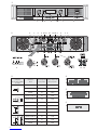 3
3
-
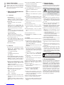 4
4
-
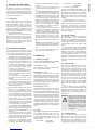 5
5
-
 6
6
-
 7
7
-
 8
8
-
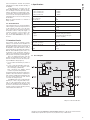 9
9
-
 10
10
-
 11
11
-
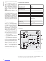 12
12
-
 13
13
-
 14
14
-
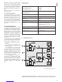 15
15
-
 16
16
-
 17
17
-
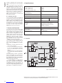 18
18
-
 19
19
-
 20
20
-
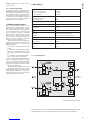 21
21
-
 22
22
-
 23
23
-
 24
24
-
 25
25
-
 26
26


Stageline STA-250 Manuale utente
- Categoria
- Amplificatore per strumenti musicali
- Tipo
- Manuale utente
in altre lingue
- English: Stageline STA-250 User manual
- français: Stageline STA-250 Manuel utilisateur
- español: Stageline STA-250 Manual de usuario
- Deutsch: Stageline STA-250 Benutzerhandbuch
- polski: Stageline STA-250 Instrukcja obsługi
Altri documenti
-
IMG Stage Line STA-1000 Manuale utente
-
-
IMG STAGELINE 24.4220 Manuale del proprietario
-
LD Systems IPA 412 T Manuale del proprietario
-
-
 Carpower WANTED-4/320 Istruzioni per l'uso
-
A.E.B. HPA 1400 Manuale utente
-
Audison LR 605 XR Manuale utente
-
 Carpower WANTED-2/160 Istruzioni per l'uso
-
HK Audio RL 112 F Manuale utente

