Genelec 8430A IP SAM Studio Monitor Istruzioni per l'uso
- Categoria
- Attrezzatura musicale
- Tipo
- Istruzioni per l'uso
Questo manuale è adatto anche per

Genelec 8430A
IP Smart Active Monitor
Operating Manual
8430A

General Description
The Genelec 8430A is a two-way smart active
monitors designed for demanding professional
audio-over-IP applications using interoperable
AES67 format.
Genelec Smart Active Monitor™ (SAM™)
digital signal processing (DSP) built inside each
smart active monitor with Genelec Loudspeaker
Manager™ (GLM™) software provides unpar-
alleled acoustic quality, ease of use, and high
monitoring accuracy even in dicult acoustic
environments. The high performance drivers are
directly connected to dedicated Class D power
ampliers. System protection is implemented
as a part of the SAM signal processing.
The MDE™ (Minimum Diffraction Enclo-
sure™) enclosure is made of die-cast alumin-
ium and shaped to reduce edge diffraction.
Combined with the advanced Directivity Control
Waveguide
TM
(DCW
TM
), this design contributes
to the excellent acoustic neutrality.
Delivery Contents
Each monitor is supplied with a mains cable, two
5 meter RJ45 cables and this operating manual
.
Connections
When using analogue signal input, before con-
necting, switch o the monitors. Once all the
analogue connections have been made, the
monitors can be switched on.
Mains Power
The power switch is located on the back panel
(see Figure 2). Connect to a mains socket
having a protective earthed connection. These
monitors can be connected to any mains volt-
age in the range 100-240 VAC, 50-60 Hz.
GLM Control Network
To run the acoustic setup process, the monitors
and subwoofers are connected to a computer
using the GLM Adapter. An RJ45 cable is sup-
plied for this. Start control GLM control network
cabling from the GLM Adapter and daisy-chain
all monitors and subwoofers (see Figure 3). No
special sequence is necessary.
Analog Audio Input
The analog audio input on both models accepts
a balanced male XLR connector.
AES67 Audio-over-IP Input
The 8430A digital audio input accepts a Ether-
net cable (RJ45 connector) carrying an AES67
formatted digital audio signal. The 8430 can be
congured to receive one or two channels in an
audio stream.
Setting up the Audio Stream
The audio stream is set up using the web page
inside the 8430A product. Before attempting
setup, connect the monitor to the IP network
switch device. Also connect your computer to
the same network. To display this setup page,
open a web browser and write in the address
eld the product identier printed in the back of
the monitor (example of address eld content
http://8430A-xx-xx-xx.local./ for a monitor with
the address 8430A-xx-xx-xx) or alternatively
write the IP address the DHCP has assigned
for the monitor. To use the product identier
printed in the back of the monitor you must
have the Bonjour protocol installed in the com-
puter you use for the setup. The Bonjour pro-
tocol software kits are available from several
sources.
You will see a setup page. All 8430A moni-
tors on the same network are visible as sym-
bols on the top of the setup page. Select the
monitor you want to set up by clicking on one
of these. Then, use the elds in the bottom of
the page to select the stream and the chan-
nel in the stream for this monitor. Work through
all the speakers until you have assigned all the
inputs to monitors. We recommend you assign
a stream to input one. In some cases you
may need to manually insert the SDP session
descriptor of the stream and channel you want
to reproduce.
After you have all the inputs set, start the GLM
software and select the digital audio input. If you
followed the recommendation above, select
input channel A. To change to another audio
stream, use the web page inside the monitor.
There are some requirements for the AE67
network. The network must run a clock source
supporting the Precision Time Protocol accord-
ing to the format dened in IEEE 1588-2008.
Several audio sources and media IP switch
devices can act as PTP clock sources for the
network. It is also useful to make sure that the
IP switches delivering the audio streams have
been configured to prioritize the PTP clock
messages and the RTP audio streams over
other trac.
The global receiver delay determines the
time from the source device output to the time
of reproduction at the destination device. If this
time is too short, the samples will not arrive
to the destination device in time because of
network delay and the destination device will
discard these samples. Too large a delay can
cause the received samples to fall out of the
receiver buer and be discarded. The maximum
delay is very large and depends on the network
settings.
Settings and Acoustic Calibration
The Smart Active Monitors are extremely exi-
ble in compensating the acoustic inuences of
the room and support automated setup using
the GLM User Kit and software. The 8430A are
compatible with GLM 2.0 and later.
The GLM software can be downloaded from
Genelec web site (www.genelec.com/glm). The
GLM 2.0 User Kit is needed for the acoustic
setup and calibration. The GLM User Kit con-
tains a GLM Adapter and GLM measurement
microphone.
The GLM Adapter is connected to the com-
puter USB port and the GLM network. The
GLM measurement microphone is placed at
the listening location. Follow the instructions in
the GLM software to acoustically calibrate the
monitors.
ISS
TM
Autostart Function
Intelligent Signal Sensing
TM
(ISS
TM
) enables very
low standby power consumption, less than 0.5
watts.
The ISS function can be enabled by click-
ing the “ISS Power Saving” pulldown menu in
the GLM software. This menu also provides a
selection of the time before entering standby.
The playback resumes once an input signal is
detected. There is a slight delay before play-
back resumes.
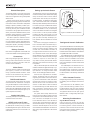
Mounting Considerations
Align the Monitors Correctly
Place and point the monitors so that their
acoustic axes (see gure 1) are aimed towards
the listening position. Vertical orientation is
preferred, as this minimises the sound colour
change around the crossover frequency when
the listener is moving horizontally.
Figure 1: Location of the acoustic axis
> 0,7 m
ACOUSTIC
AXIS
H
H = 190 mm (7 1/2 in)

Maintain Symmetry
Place the monitors at an equal distance from
the listening position and symmetrically relative
to the room walls. Place the listening position
on the room front-back centreline and the moni-
tors at an equal distance from this centreline.
Minimise Reections
Acoustic reflections are created by objects
close to the monitors. Such objects can be
desks, cabinets, computer monitors etc.
Acoustic reections can cause unwanted sound
colouration and sound image instability. These
can be minimised by placing the monitors and
the listening position clear of reective surfaces.
Minimum Clearances
Ensure sucient clearance for amplier cooling
and reex port function. The minimum clearance
is 3 cm (13/16 in) behind, above, and on both
sides of the monitor. The ambient temperature
should be less than 35 degrees Celsius (95°F.
)
Mounting Options
The Genelec 8430A oers the Iso-Pod™ (Isola-
tion Positioner/Decoupler™) vibration insulat-
ing stand allowing tilting of the monitor acous-
tic axis towards the listener. The bottom of the
monitor has a 3/8 in UNC thread. The rear has
two M6 x 10 mm threads for wall or ceiling
mounts. Genelec oers a selection of mounting
accessories.
Safety Considerations
Servicing must only be performed by qualied
service personnel. The monitor must not be
opened.
• Do not use the monitor with an unearthed
mains cable or an unearthed mains
connection.
• Do not expose the monitor to water or
moisture. Do not place any objects lled
with liquid, such as vases, on the monitor
or near it.
• This monitor is capable of producing
sound pressure levels in excess of 85 dB,
which may cause permanent hearing
damage.
• Free ow of air behind the monitor is
necessary to maintain sucient cooling. Do
not obstruct airow around the monitor.
• The device is not completely disconnected
from the AC mains service unless the mains
power cord is detached from the device or
the mains outlet.
Guarantee
This product is guaranteed for a period of two
years against faults in materials or workman-
ship. Refer to supplier for full sales and guar-
antee terms.
Compliance to FCC Rules
This device complies with part 15 of the FCC
Rules. Operation is subject to the following two
conditions:
This device may not cause harmful interfer-
ence, and this device must accept any interfer-
ence received, including interference that may
cause undesired operation.
Note: This equipment has been tested and
found to comply with the limits for a Class B
digital device, pursuant to part 15 of the FCC
Rules. These limits are designed to provide
reasonable protection against harmful interfer-
ence in a residential installation. This equip-
ment generates, uses and can radiate radio
frequency energy and, if not installed and used
in accordance with the instructions, may cause
harmful interference to radio communications.
However, there is no guarantee that interfer-
ence will not occur in a particular installation. If
this equipment does cause harmful interference
to radio or television reception, which can be
determined by turning the equipment o and
on, the user is encouraged to try to correct the
interference by one or more of the following
measures:
• Reorient or relocate the receiving antenna.
• Increase the separation between the
equipment and receiver.
• Connect the equipment into an outlet on
a circuit dierent from that to which the
receiver is connected.
• Consult the dealer or an experienced
radio/TV technician for help
Modications not expressly approved by the
manufacturer could void the user’s authority to
operate the equipment under FCC rules.
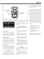
Figure 2: Connector layout on the rear panel of the 8430A.
292-8030W
COMPOSANTÀL'INTÉRIEURREMPLAÇABLEPAR
OUVRIR.NE PASEXPOSERÀL'EAUOUL'HUMIDITÉ. AUCUN
L'UTILISATEUR.ADRESSER TOUTE RÉPARATION ÀUN
PERSONNELQUALIFIÉ.CETAPPAREIL DOITÊTRE
RACCORDÉÀLATERRE.
NOTSUBJECT TO WATER ORMOISTURE. NO USER SERVICEABLE
PARTSINSIDE.REFER SERVICINGTO QUALIFIED PERSONNEL.
USEEARTHED MAINS CONNECTION ONLY.
ELECTRICSHOCK HAZARD. DO NOT OPEN.DO
WARNING:
RISQUEDE CHOC ÉLECTRIQUE. NE PASAVERTISSEMENT:
LAITEONLIITETTÄVÄSUOJAMAADOITUSKOSKETTIMILLA VARUS-
TETTUUNPISTORASIAAN. APPARATETMÅTILKOPLESJORDET
STIKKONTAKT.APPARATENSKALLANSLUTASTILL JORDATUTTAG.
MADE IN FINLAND
www.genelec.com
SERIAL NUMBER
292-8430T-6
ANALOG
IN
+
- GND
2
3
1
IN
MAINSINPUT
50 /60Hz60W
100 -240 V~
ETHERNET
8430A
SMART ACTIVE MONITOR
GLMNETWORK
RESET TO FACTORY
SETTINGS: PUSH
BUTTONFOR 10 SEC
GLM
NETWORK
CONNECTORS
MAINS
INPUT
ETHERNET
AND
ANALOG INPUT
Figure 3: Connector panel of the 8430A.

8430A Operating Manual
Genelec Document D0136R001a. Copyright Genelec Oy 11.2017. All data subject to change without prior notice
International enquiries:
Genelec, Olvitie 5
FIN-74100, Iisalmi, Finland
Phone +358 17 83881
Fax +358 17 812 267
Email [email protected]
In the U.S. please contact:
Genelec Inc., 7 Tech Circle
Natick, MA 01760, U.S.A.
Phone +1 508 652 0900
Fax +1 508 652 0909
Email [email protected]
www.genelec.com
In Sweden please contact
Genelec Sverige
Ellipsvägen 10B
P.O. Box 5521, S-141 05 Huddinge
Phone +46 8 449 5220
Fax +46 8 708 7071
Email [email protected]
In China please contact:
Beijing Genelec Audio Co.Ltd
Room 101, 1st oor
Building 71 B33, Universal Business Park
No. 10 Jiuxianqiao Road, Chaoyang District
Beijing, China
Phone +86 (10) 5823 2014
Post code: 100015
Email [email protected]
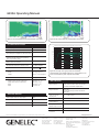
Figure 4: The horizontal directivity characteristics of the 8430.
Figure 5: The vertical directivity characteristics of the 8430.
Frequency range –6 dB: 45 Hz – 23 kHz
Accuracy of frequency response: ±1.5 dB (58 Hz – 20 kHz)
Maximum short term sine wave acoustic output on
axis in half space, averaged from 100 Hz to 3 kHz:
> 104 dB SPL
Maximum long term RMS acoustic output in same
conditions with IEC weighted noise (limited by
driver unit protection circuit):
> 96 dB SPL
Maximum peak acoustic output per pair, 1 m
distance with music material:
> 110 dB
Self generated noise level in free eld on axis: < 5 dB (A weighted)
Harmonic distortion at 85 dB SPL on axis: 50…100 Hz < 2 %
>100 Hz < 0.5 %
Drivers:
Woofer
Tweeter
130 mm (5 in) cone
19 mm (
3
/
4
in) metal dome
Weight: 5.5 kg (12.1 lb)
Dimensions:
Height including Iso-Pod™ table stand
Height without Iso-Pod™ table stand
Width
Depth
299 mm (11
13
/
16
in)
285 mm (11
1
/
4
in)
189 mm (7
7
/
16
in)
178 mm (7 in)
Bass amplier short term output power
Treble amplier short term output power
50 W
50 W
Total harmonic distortion at nominal output <0.05%
Mains voltage 100-240 VAC, 50-60 Hz
Power consumption (ISS active / idle / maximum) < 0.5 W / 3.0 W / 50 W
SYSTEM SPECIFICATIONS
AMPLIFIER SECTION
INPUT SECTION
Audio-over-IP format and
input connector
AES67 and RAVENNA
RJ45 connector with or without an XLR shell
Fast Ethernet 100BASE-TX (IEEE 802.3)
Audio-over-IP input word
length and format
L16 (16 bits), xed point linear PCM fraction
(RFC1890)
L24 (24 bits), xed point linear PCM fraction
(RFC3190)
Audio-over-IP Input
sampling rate
44.1, 48, 88.2, 96 kHz
Crossover frequency 2.9 kHz
Analog input
(load impedance)
XLR female (10 kOhm, balanced)
Analog input level for 100
dB SPL output at 1 meter
-6 dBu (adjustable in GLM software)
Maximum analog input 24 dBu
GLM Control network
connectors
2 x RJ45
Figure 6: The upper curve group shows the horizontal
characteristics of the 8430A measured at 1 meter distance. The
lower curve shows the power response of the 8430.
20
20k
50
100
200
500
1k 2k
5k
10k
Hz
Genelec Oy 8430 horizontal off axis response level (dBr) vs freq (Hz)2Feb 16
0°
60°
15°
30°
45°
50
100
55
60
65
70
75
80
85
90
95
d
B
r
A
-
 1
1
-
 2
2
-
 3
3
-
 4
4


Genelec 8430A IP SAM Studio Monitor Istruzioni per l'uso
- Categoria
- Attrezzatura musicale
- Tipo
- Istruzioni per l'uso
- Questo manuale è adatto anche per
in altre lingue
Documenti correlati
Altri documenti
-
GameSir VXAIMBOX Manuale utente
-
Dell PowerEdge 2450 Guida utente
-
Electrolux ESCGL.3SW Manuale utente
-
WIKA DI32-1 Istruzioni per l'uso
-
Rowenta BRUSH ACTIV' VOLUME & SHINE Manuale del proprietario
-
Whirlpool AWT 3088 Guida utente
-
MOTO GUZZI CALIFORNIA 1000i Workshop Manual
-
LG WD-T12235DA Manuale del proprietario