Modbus RS485
485
Memory card
Ethernet
ww w.danfoss.com/mcx
MAKING MODERN LIVING POSSIBLE
www.danfoss.com/mcx
MAKING MODERN LIVING POSSIBLE
Via San Giuseppe 38/G
31015 Conegliano
(TV) Italy
Tel: +39 0438 336611
Fax: +39 0438 336699
info.mcx@danfoss.com
www.danfoss.com
MCX152V - TOP
MCX152V- BOTTOM
white
black
red
green
STEPPER
MOTOR 2
RS485-1
SD/MMC
ST2 4
ST2 3
ST2 2
ST2 1
COM 1
D1 +
D1 -
RS485-2
COM 2
D2 +
D2 -
DIGITAL INPUT 18
DIGITAL OUTPUT 9-12 DIGITAL OUTPUT 13-15
STEPPER BACKUP
COM
+ BATT
DIGITAL INPUT 1-8 DIGITAL INPUT 9-16
POWER
SUPPLY
L
N
MEMORY CARD ANALOG OUTPUT 1-6 ANALOG INPUT 1-7
CAN CAN-RJ
ETHERNET DIGITAL INPUT 17
ANALOG INPUT 8-14
RS485
(Modbus)
supervisory
network
CANbus
CANbus
local network
COM
CANL
CANH
R120
COM 17
DI 17
DIGITAL OUTPUT 6-8
NO 8
C 8
NO 7
C 7
NO 6
C 6
DIGITAL OUTPUT 1-5
NO 3
C 3
NO 2
C 2
NO 5
C 5
NO 4
C 4
NO 1
C 1
CAN-RJ
CANbus
ETH
supervisory
network
MMIGRS
N
L
N
L
N
L
5 A
AO 1
AO 2
AO 3
5 A
5 A
5 A
5 A
5 A
5 A
5 A
white
black
red
green
orange
yellow
Red
black
orange
yellow
Red
black
STEPPER
MOTOR 1
ST1 4
ST1 3
ST1 2
ST1 1
PWM-PPM-0/10 V
UNIVERSAL
UNIVERSAL
UNIVERSAL
PROGRAMMABLE
PROGRAMMABLE
PROGRAMMABLE
0/10 V
0/10 V
AO 4
AO 5
AO 6
PWM-PPM-0/10 V
0/10 V
0/10 V
AO 6
AO 5
AO 4
COM
AO 3
AO 2
AO 1
COM
NTC, Pt1000,
ON/OFF, 0/1 V,
0/5 V, 0/10 V,
0/20 mA, 4/20 mA
+
18 V
BAT T
BACKUP
UNIVERSAL
UNIVERSAL
UNIVERSAL
PROGRAMMABLE
Out only backup battery
NTC, Pt1000,
ON/OFF, 0/1 V,
0/5 V, 0/10 V,
0/20 mA, 4/20 mA
PROGRAMMABLE
PROGRAMMABLE
PROGRAMMABLE
DI 17H
7 A
7 A
7 A
7 A
7 A
7 A
5 A
5 A
5 A
5 A
15V+
COM
DI 9
DI 10
DI 11
DI 12
COM
DI 13
DI 14
DI 15
DI 16
COM
DI 1
DI 2
DI 3
DI 4
COM
DI 5
DI 6
DI 7
DI 8
DI 18H
DI 18
COM 18
C 9
NO 9
C 10
NO 10
C 11
NO 11
C 12
NO 12
C 13
C 13
NO 13
NC 13
C 14
NO 14
NC 14
C 15
NO 15
NC 15
To the AI
To the AI
To the AI
To the AI
COM
COM
15V+
AI 7
AI 6
AI 5
5V+
AI 4
AI 3
AI 2
AI 1
COM
COM
15V+
AI 14
AI 13
AI 12
5V+
AI 11
AI 10
AI 9
AI 8
PROGRAMMABLE
ETS/KWS
valves
Saginomya
valves
110
280 6063
Foglio istruzioni
Controllo elettronico
MCX152V
Foglio istruzioni
Controllo elettronico
MCX152V
AVVERTENZE
CARATTERISTICHE CONTENITORE PLASTICO
- Agganciabile su guida DIN secondo EN 60715
- Autoestinguenza V0 secondo IEC 60695-11-10 e comportamento al filo incandescente 960 °C secondo IEC 60695-2-12
- Prova biglia: 125 °C secondo IEC 60730-1. Resistenza alle correnti superficiali: ≥ 250 V secondo IEC 60112
ALTRE CARATTERISTICHE
- Condizioni di funzionamento CE: -20T55, 90 % UR non condensante
- Condizioni di immagazzinamento: -30T80, 90 % UR non condensante
- Da integrare in apparecchiature di classe I e/o II
- Grado di protezione: IP40 sul solo frontale
- Periodo di sollecitazione elettriche delle parti isolanti: lungo
- Adatto per l’uso in ambiente con grado di polluzione normale
- Categoria di resistenza al calore e al fuoco: D
- Immunità contro le sovratensioni: categoria II
- Classe e struttura del software: A
CONFORMITÀ CE
Questo prodotto è progettato in modo da garantire la conformità con le seguenti direttive dell’Unione Europea:
- Direttiva bassa tensione: 73/23/EEC
- Compatibilità elettromagnetica EMC: 89/336/EEC e con le seguenti norme armonizzate:
- EN61000-6-1, EN61000-6-3 (immunità ed emissione per gli ambienti residenziali, commerciali e
- dell’industria leggera)
- EN61000-6-2, EN61000-6-4 (immunità ed emissione per gli ambienti industriali)
- EN60730 (dispositivi elettrici automatici di comando per uso domestico e similare)
AVVERTENZE
- Ogni utilizzo diverso da quanto descritto nel presente manuale è da ritenersi improprio e non è pertanto autorizzato
- Verificare che le condizioni limite di funzionamento a cui l’apparecchiatura è sottoposta rientrino
tra quelle specificate, in particolare per quanto riguarda la tensione di alimentazione e le condizioni ambientali
- Questa apparecchiatura contiene componenti elettrici sotto tensione e pertanto tutte le operazioni di
servizio e manutenzione su di essa possono essere eseguite solo da personale qualificato
- L’apparecchiatura non può essere utilizzata come dispositivo di sicurezza
- La responsabilità di lesioni o danni causati da uso improprio ricadrà esclusivamente sull’utilizzatore
AVVERTENZE PER L’INSTALLAZIONE
- Posizione di montaggio raccomandata: verticale
- L’installazione deve essere eseguita secondo le normative e legislazioni vigenti nel paese di utilizzo dell’apparecchiatura
- Operare sui collegamenti elettrici sempre ad apparecchiatura non alimentata
- Prima di effettuare qualsiasi operazione di manutenzione sulla apparecchiatura, disinserire tutti i collegamenti elettrici
- Per motivi di sicurezza l’apparecchiatura deve essere alloggiata all’interno di un quadro elettrico ed in
particolare, in condizioni normali, non dovranno essere accessibili parti in tensione pericolosa
- Non esporre l’apparecchiatura sotto continui getti d’acqua o ad un umidità maggiore del 90 %. In
generale evitare l’esposizione ad atmosfere aggressive ed inquinanti, agli agenti atmosferici, ad ambienti
ove sono presenti esplosivi o miscele di gas infiammabili, alla polvere, a forti vibrazioni, a repentine
variazioni di temperatura che abbinate ad alta umidità possono provocare la formazione di condensa e
a fonti di interferenze elettromagnetiche (ad es. antenne trasmittenti)
- Nel collegamento dei carichi tenere in considerazione la massima corrente applicabile a ciascun relè e morsetto
- Utilizzare capicorda adatti per i morsetti in uso; dopo la chiusura delle viti dei morsetti, tirare
leggermente i cavi per verificarne la tenuta
- Usare cavo appropriato per le linee di comunicazione. Fare riferimento alla Guida di Installazione
“MCX hardware network specification” per il tipo di cavo da usare e le raccomandazioni da osservare nei
collegamenti
- Ridurre il più possibile il percorso dei cavi dei sensori e degli ingressi digitali, allontanandoli dai cavi dei
carichi induttivi e di potenza per evitare possibili disturbi elettromagnetici
- Non avvicinare le dita ai componenti elettronici dell’apparecchiatura per evitare la generazione di scariche elettrostatiche
DKRCC.PI.RI0.G3.1U / 520H7793 - MCX152V foglio istruzioni - P.N. 3106000510 - 15-310600051-C
Danfoss Electronic Controllers & Services, AZ Giugno 2013
La Danfoss non si assume alcuna responsabilità circa eventuali errori nei cataloghi, pubblicazioni o altri documenti scritti. La Danfoss si riserva il diritto di modicare i suoi prodotti senza previo avviso,
anche per i prodotti già in ordine sempre che tali modiche si possano fare senza la necessità di cambiamenti nelle speciche che sono già state concordate.
Tutti i marchi di fabbrica citati sono di proprietà delle rispettive società. Il nome Danfoss e il logo Danfoss sono marchi depositati della Danfoss A/S. Tutti i diritti riservati.
SMALTIMENTO DEL PRODOTTO
- L’apparecchiatura (o il prodotto) deve essere oggetto di raccolta separata in conformità alle vigenti
normative locali in materia di smaltimento.
SCHEMA DI COLLEGAMENTO
SCHEDA SUPERIORE SCHEDA INFERIORE
*NOTA: collegamento da effettuare sui due strumenti posti all’estremità della rete locale, la connessione deve essere realizzata il più vicino possibile al connettore
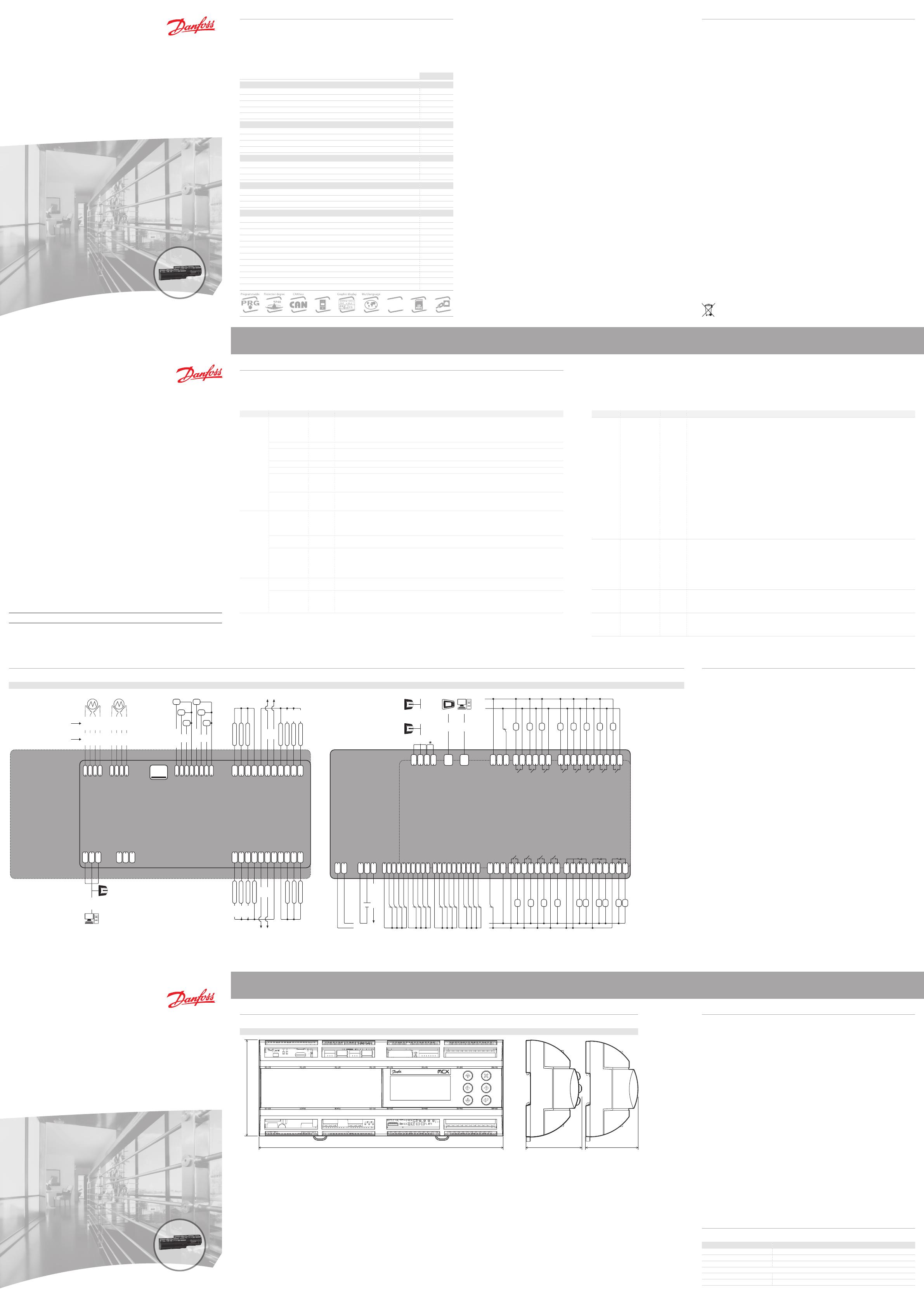
DIMENSIONI
Display LCD Senza display
CARATTERISTICHE GENERALI
MCX152V è un controllo elettronico standard MCX che si posiziona ai vertici della gamma MCX grazie al suo
elevato numero di ingressi e uscite e ai 2 driver integrati per valvola di espansione elettronica. E’ disponibile nelle
versioni con o senza display LCD grafico e alimentazione a 110-230 Vac o 24 Vac. Racchiude al suo interno tutte le
funzionalità tipiche dei controlli MCX: programmabilità, possibilità di collegamento in rete locale CANbus e fino
a due seriali di comunicazione Modbus RS485. E’ dotato anche di un alloggio per scheda di memoria SD/MMC
e connessione a rete Ethernet. La scheda di memoria può essere utilizzata per il caricamento del software e la
memorizzazione dei dati storici; la porta Ethernet permette il download del software, il monitoraggio attraverso
pagine web, la registrazione dei dati e la segnalazione degli allarmi.
MCX152V
INGRESSI ANALOGICI
NTC, Pt1000, 0/1 V, 0/5 V, 0/10 V, 0/20 mA, 4/20 mA, configurabili da software 8
NTC, 0/1 V, 0/5 V, 0/10 V, 0/20 mA, 4/20 mA, configurabili da software 6
Superheat S1: 0/1 V, 0/5 V, 0/10 V, 0/20 mA, 4/20 mA, configurabili da software 2
Superheat S2: PT1000, 0/1 V, 0/5 V, 0/10 V, configurabili da software 2
Numero totale 14
INGRESSI DIGITALI
Contatto pulito 16
24 V optoisolato 2
230 Vac optoisolato 2
Numero totale 18
USCITE ANALOGICHE
0/10 Vdc 6
0/10 V, PWM, PPM configurabili da software 2
Numero totale 6
USCITE DIGITALI
SPST relè 5 A (contatto normalmente aperto) 12
SPDT relè 16 A (contatto in scambio) 3
Numero totale 15
ALTRI
Alimentazione 24 Vac •
Alimentazione 110 V/230 Vac •
Connessione per chiave di programmazione •
Connessione per terminale tastiera remoto •
CANbus •
Orologio RTC •
Seriale Modbus RS485 •
Ethernet/Webserver •
Slot di espansione SD (Secure Digital) o MMC (Multi Media Card) fino a 2 GB •
Uscita motore bipolare e unipolare •
Dimensioni (moduli DIN) 16
Montaggio barra DIN
DATI TECNICI
ALIMENTAZIONE
- 85 Vac a 265 Vac, 50-60 Hz. Massima potenza assorbita: 27 W, 48 VA. Isolamento garantito dall’alimentazione rispetto alla bassissima tensione: rinforzato
- 24 Vac ± 15 % 50/60 Hz. Massima potenza assorbita: 27 W, 43 VA. Isolamento garantito dall’alimentazione rispetto alla bassissima tensione: funzionale
I/O TIPO NUMERO CARATTERISTICHE
Ingressi
analogici
Max tensione di entrata 15 V
Non collegare sorgenti di tensione, senza limitazione di corrente (80 mA complessivo) agli ingressi
analogici mentre l’unità non è alimentata
Diagnostica HW circuito aperto disponibile per tutti gli ingressi analogici
0/1 V, 0/5 V, 0/10 V 14
AI1, AI2, AI3, AI4, AI5, AI6, AI7, AI8, AI9, AI10, AI11, AI12, AI13, AI14
NTC 14
AI1, AI2, AI3, AI4, AI5, AI6, AI7, AI8, AI9, AI10, AI11, AI12, AI13, AI14
Sonde di temperatura NTC, default: 10kΩ a 25 °C
0/20 mA; 4/20 mA 8
AI1, AI2, AI3, AI5, AI8, AI9, AI10, AI12
Pt1000 8
AI1, AI2, AI3, AI7, AI8, AI9, AI10, AI14
Ingresso
differenziale
2
AI5(-),AI6(+);
AI12(-), AI13(+)
Ingresso differenziale, DM tensione 0..300 mV; CM tensione max 14 V
Forniture ausiliarie 2
15 V+ e 5 V+
5 V+ max: 140 mA (totale uscite)
15 V+ max: 200 mA (totale uscite)
Ingressi
digitali
Contatto pulito 16
DI1, DI2
Durata minima dell’impulso 2,5 ms
DI3, DI4, DI5, DI6, DI7, DI8, DI9, DI10, DI11, DI12, DI13, DI14, DI15, DI16
Durata minima dell’impulso 64 ms
24 V optoisolato 2
DI17, DI18
Ingressi optoisolati a 24 Vac 50/60 Hz o 24 Vdc. Corrente nominale: 5 mA
230 Vac optoisolato 2
DI17, DI18
Ingressi optoisolati a 230 Vac 50/60 Hz. Isolamento principale.
Corrente nominale: 2 mA a 230 Vac; 1 mA a 110 Vac
- NOTA: se si utilizza l’ingresso DI17H a 230 Vac il corrispondente ingresso DI17 a 24 V non è più disponibile;
analogo discorso per le coppie di ingressi DI18H and DI18
Uscite
analogiche
0/10 Vdc 4
AO1, AO2, AO3, AO4, AO5, AO6
Corrente max: 10 mA
PWM, PPM 2
AO3, AO6
- uscita ad impulsi, sincrona con la rete, a modulazione di posizione di impulso (PPM)
o di larghezza di impulso (PWM): tensione a vuoto di 6,8 V
- uscita ad impulsi, PWM nel range da 20 Hz a 1 kHz: tensione a vuoto di 6,8 V
I/O TIPO NUMERO CARATTERISTICHE
Uscite
digitali
Relè 15
Per quanto riguarda la distanza d’isolamento i relè si possono riunire in tre gruppi:
- gruppo 1: relè 1 a 8
- gruppo 2: relè 9 a 12
- gruppo 3: relè 13 a 15
Isolamento tra i relè dello stesso gruppo: funzionale
Isolamento tra i relè di gruppi diversi: rinforzato
Isolamento tra i relè e la bassissima tensione: rinforzato
C1-NO1 a C12-NO12
Relè da 5 A con contatto normalmente aperto
- caratteristiche di carico di ogni relè:
5 A 250 Vac per carichi resistivi - 100.000 cicli
3 A 250 Vac per carichi induttivi - 100.000 cicli con cos(phi) = 0.4
C13-NO13 a C15-NO15
Relè da 16 A con contatto normalmente aperto
- caratteristiche di carico di ogni relè:
7 A 250 Vac per carichi resistivi - 100.000 cicli
3.5 A 250 Vac per carichi induttivi - 230.000 cicli con cos(phi) = 0.4
C1-NO1, C2-NO2, C3-NO3, C15-NO15
Opzionalmente possono essere relè a stato solido
- caratteristiche di carico di ogni relè:
15-280 Vrms, 1 A
Stepper
motor
2
ST1, ST2, ST3, ST4
Uscita stepper motor bipolare e unipolare:
- valvole ETS Danfoss (verde, rosso, nero, bianco)
- Saginomyia UKV/SKV/VKV/PKV (nero, rosso, giallo, arancione)
- altre valvole:
drive mode 1/8 microstep
picco di corrente di fase: 500 mA
max tensione di pilotaggio 30 V
max potenza in uscita 4,6 W
Batteria di
backup
1
BAT T
18-24 Vdc:
- dispersione corrente max 12 μA
- corrente max della batteria: 0,5 A @ 18 V
Memory card 1
SD/MMC
Max 2 GB:
- per la registrazione dei dati assicurarsi che la scheda di memoria sia ferma al suo posto
- evitare installazioni con vibrazioni
CONNESSIONI
SCHEDA SUPERIORE
- Connettore Stepper motor 2
4 vie tipo morsetto a molla estraibile passo 2,5 mm: sezione cavo 0,2-0,5 mm²
- Connettore Stepper motor 1
4 vie tipo morsetto a molla estraibile passo 2,5 mm: sezione cavo 0,2-0,5 mm²
- Connettore Memory card
SD/MMC card slot
- Connettore analog output 1-6
8 vie tipo morsetto a vite estraibile passo 2,5 mm: sezione cavo 0,2-1,5 mm²
- Connettore analog input 1-7
11 vie tipo morsetto a vite estraibile passo 5 mm: sezione cavo 0,2-2,5 mm²
- Connettore RS485-1
3 vie tipo morsetto a vite estraibile passo 5 mm: sezione cavo 0,2-2,5 mm²
- Connettore RS485-2
3 vie tipo morsetto a vite estraibile passo 5 mm: sezione cavo 0,2-2,5 mm²
- Connettore Analog input 8-14
11 vie tipo morsetto a vite estraibile passo 5 mm: sezione cavo 0,2-2,5 mm²
SCHEDA INFERIORE
- Connettore CAN
4 vie tipo morsetto a vite estraibile passo 5 mm: sezione cavo 0,2-2,5 mm²
- Connettore CAN-RJ
6/6 vie tipo telefonico RJ11 plug
- Connettore Ethernet
8/8 vie tipo RJ45 plug
- Connettore digital input 17
3 vie tipo morsetto a vite estraibile passo 5 mm: sezione cavo 0,2-2,5 mm²
- Connettore digital output 6-8
6 vie tipo morsetto a vite estraibile passo 5 mm: sezione cavo 0,2-2,5 mm²
- Connettore digital output 1-5
10 vie tipo morsetto a vite estraibile passo 5 mm: sezione cavo 0,2-2,5 mm²
- Connettore power supply
2 vie tipo morsetto a vite estraibile passo 5 mm: sezione cavo 0,2-2,5 mm²
- Connettore Stepper backup
3 vie tipo morsetto a vite estraibile passo 5 mm: sezione cavo 0,2-2,5 mm²
- Connettore digital input 1-8
10 vie tipo morsetto a molla estraibile passo 2,5 mm: sezione cavo 0,2-0,5 mm²
- Connettore digital input 9-16
10 vie tipo morsetto a molla estraibile passo 2,5 mm: sezione cavo 0,2-0,5 mm²
- Connettore digital input 18
3 vie tipo morsetto a vite estraibile passo 5 mm: sezione cavo 0,2-2,5 mm²
- Connettore digital input 9-12
8 vie tipo morsetto a vite estraibile passo 5 mm: sezione cavo 0,2-2,5 mm²
- Connettore digital input 13-15
10 vie tipo morsetto a vite estraibile passo 5 mm: sezione cavo 0,2-2,5 mm²
INTERFACCIA UTENTE
DISPLAY LCD
- tipo: grafico STN blu trasmissivo
- retroilluminazione: a LED bianchi con intensità regolabile da software
- risoluzione: 128x64 punti
- area visibile attiva: 58x29 mm
- contrasto: regolabile da software
TASTIERA
- numero di tasti: 6
- la funzione dei tasti è impostabile da software
CODICI IDENTIFICATIVI DEL PRODOTTO
CODE DESCRIPTION
080G0284 MCX152V, 24V, LCD, 2 RS485, ETH, S
080G0285 MCX152V, 230V, LCD, 2 RS485, ETH, S
080G0306 MCX152V, 24V, LCD, 2 RS485, S
080G0296 MCX152V, 24V, RS485, S
080G0313 MCX152V, 24V, 2 RS485, S

