ThermoKey DFC 150 10 06 Technical Manual
- Tipo
- Technical Manual

MT TC A DF GEN 04 2017
Technical Manual – TC
Technisches Handbuch – TC
Manuel Technique – TC
Manuale tecnico – TC
Manual técnico – TC
PodrEcznik techniczny – TC
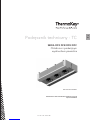
Series DFX, DFB, DFN, DFC
Industrial dual flow unit coolers and brine coolers
Serie DFX, DFB, DFN, DFC
Hochleistungsverdampfer mit Doppelblock
und Kaltsole-Verdampfer für den Industriegebrauch
Série DFX, DFB, DFN, DFC
Évaporateurs et frigorifères industriels double flux
Serie DFX, DFB, DFN, DFC
Aeroevaporatori e aerorefrigeratori industriali a doppio flusso
Serie DFX, DFB, DFN, DFC
Aeroevaporadores y aerorrefrigeradores industriales double flujo
Seria DFX DFB DFN DFC
Chłodnice z podwójnym wydmuchem powietrza
THE ORIGINAL VERSION OF THESE
INSTRUCTIONS IS IN ITALIAN
EN
IT
DE
ES
FR
PL


Heat Exchange SolutionsThermoKey Technical Manual TC Instruction and technical data
0605
EN
MT TC A DF EN 04 2017MT TC A DF EN 04 2017
CAREFULLY READ AND FULLY UNDERSTAND ALL INFORMATION
CONTAINED IN THESE INSTRUCTIONS PRIOR TO DESIGNING AND
IN ANY CASE BEFORE PERFORMING ANY HANDLING, UNPACKING,
ASSEMBLING, INSTALLATION AND COMMISSIONING OF THE UNIT.
THE MANUFACTURER ACCEPTS NO RESPONSIBILITY FOR DAMAGE TO
PERSONS OR PROPERTY RESULTING FROM FAILURE TO FOLLOW THE
INSTRUCTIONS CONTAINED HEREIN.
The original language of this manual is Italian, and it is available on the website:
www.thermokey.com.
The English translation is a true copy of the original document and it is available on the website:
www.thermokey.com.
Translations in other languages may contain errors; if in doubt, always refer to the original
version in Italian or its English translation.
ThermoKey S.p.A. Quality Management System is certified in conformity with ISO 9001,
ThermoKey S.p.A. Environmental Management System is certified in conformity with ISO 14001
and Safe Management System is certified in conformity with OHSAS 18001.
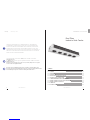
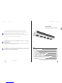
Dual Flow
Industrial Unit Cooler
TC 1. STANDARD AND DIRECTIVES REFERENCES
TC 2. HAZARDS
TC 3. WARNINGS
TC 4. INTENDED USE
TC 5. INSPECTION, HANDLING AND TRANSPORT
TC 6. INSTALLATION AND COMMISSIONING
TC 7. GENERAL MAINTENANCE AND OVERALL CONTROL
TC 8. WIRING DIAGRAMS OF ELECTRIC DEFROSTING HEATERS
TC 9. WIRING DIAGRAMS OF FANMOTORS
TC 10. DIMENSIONS
TC 11. TECHNICAL DATA
SUMMARY
07
07
08
09
09
10
13
15
20
24
28

Heat Exchange SolutionsThermoKey Technical Manual TC Instruction and technical data
0807
EN
MT TC A DF EN 04 2017MT TC A DF EN 04 2017
Danger of electrocution. The product is fitted with electric fanmotors and electric defrosting heating elements with
nominal operational low three-phase or single-phase voltage. The electric power supply lines will have to use protection
systems against electric shock and protection equipment required by law.
Risk of burns. In products fitted with electric defrosting heating elements the surface temperatures of the external armor
can reach about 350 °C if left on without control.
Risk of cutting. The internal heat exchanger is made of metal fins with unprotected sharp edges. The casing is made of
metal sheet components that may have unprotected sharp edges.
Danger of moving parts. The product is fitted with electric fanmotors equipped with a protection grille as provided by
law. For some products, it may be possible to deliberately access moving parts (fanmotor blades) from non-protected areas.
Before any access make sure that the moving parts do not constitute a hazard to operators.
Danger of squashing limbs or persons. During handling, transportation and installation, operation and maintenance,
pay maximum attention to the indicated weight of each product to prevent tipping over or dangerous falls towards the
operators.
Danger of falling objects. The products are fitted with doors, trays or covering metal sheet parts that during installation
or maintenance may be dismounted by removing the fastening screws; please take all appropriate precautions.
TC 2. Hazards
TC 1. Standard and directives references
The product described in this manual is compliant with:
MACHINERY DIRECTIVE 2006/42/EC
LOW VOLTAGE DIRECTIVE 2014/35/EU
ELECTROMAGNETIC COMPATIBILITY DIRECTIVE 2014/30/EU
PED DIRECTIVE 2014/68/EU
ERP DIRECTIVE 2009/125/EC
TC 3. Warnings
TC 3.1
Contents of the Product Technical Manual:
INSTRUCTIONS FOR SAFE USE (IG)
INSTRUCTIONS FOR HANDLING AND UNPACKING (IM)
INSTRUCTIONS AND TECHNICAL DATA (TC)
SPECIFIC INSTRUCTIONS FOR USE AND MAINTENANCE (IS)
TC 3.2
This manual is section TC, called INSTRUCTIONS AND TECHNICAL DATA, of the Product Technical Manual.
For any information not covered in this manual, please refer to the other sections (IG-IM-IS) and, if in doubt, contact
the Manufacturer.
TC 3.3
This manual is an integral part of the DFX DFB DFN and DFC units and as such it must be kept throughout the
operational life of the product.
TC 3.4
Any additional technical documentation relating to the non-standard products is attached to this manual becoming
an integral part of it and is identified with a specific code indicated on the shipping documents.
TC 3.5
The product described in this manual is considered a partly completed machine, therefore not usable as supplied, but
it is a component for air conditioning and refrigeration systems and must be installed and commissioned by qualified
operators (see the chapter related to installation and put in function).
TC 3.6
Each product is supplied with EC Declaration of Incorporation.
TC 3.7
Additional product documentation, consisting of catalogues, guides and technical bulletins, is provided directly
by ThermoKey and it is available on our website www.thermokey.com.
CATALOGUES – http://www.thermokey.com/Cataloghi.aspx
MANUALS – http://www.thermokey.com/Manuali.aspx

Heat Exchange SolutionsThermoKey Technical Manual TC Instruction and technical data
1009
EN
MT TC A DF EN 04 2017MT TC A DF EN 04 2017
TC 4. Intended use
TC 4.1
The unit should be used exclusively for the purpose indicated below, otherwise its use is considered improper and
exempts the manufacturer from any responsibility.
TC 4.2
The industrial evaporator unit cooler and brine cooler from the series DFX DFN DFB and DFC are designed for use
in all food sectors, in medium and large cold storage rooms or refrigerated warehouses for storing fresh and frozen
goods and also for cooling and air conditioning medium and large processing rooms. All standard units are equipped
with a highly efficient ventilation group for optimal air distribution.
TC 4.3
The standard unit is equipped with fanmotors not designed to withstand additional external static pressure such as
those exerted by additional ducts, abatement tunnels, etc.
TC 4.4
When in doubt on the intended use please contact the Manufacturer.
TC 5. Inspection, handling and transport
TC 5.1
Upon receipt of the unit, check the integrity of the packaging and of the product; immediately notify the carrier of any
possible damage occurred. The packaging is manufactured in accordance with the unit and the appropriate means of
transport and handling.
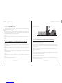
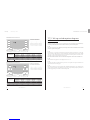
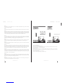
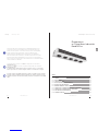
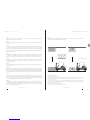
TC 5.2
During transport and handling of the unit in its packaging, avoid improper and non-compliant stress on the packed
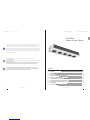
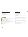
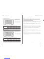
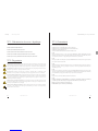
product, comply with all indications and always keep the unit in the position shown in the figure (see fig.1).
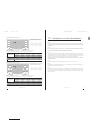
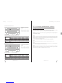
TC 5.3
During transport and handling of the packed product, use appropriate protection to avoid injury from packaging parts
such as nails, wooden boards or cardboards and from parts of the unit like fins or casing parts (see DPI Technical
Manual Section I chapter IG 6).
TC 5.4
Unpack the unit as close as possible to the installation site (see also chapter installation and commissioning). In
general, the unit should not be transported or handled without its original packaging.
TC 5.5
During handling of the unpacked unit for installation, use protection to prevent injuries from sharp edges like ns or casing
parts (see DPI Technical Manual Section I chapter IG 6).
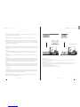
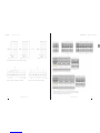
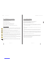
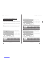
TC 6.1
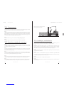
The installation and commissioning of the unit must be carried out by expert and qualified personnel. For fixing
follow the diagram shown in the figure (see fig.2).
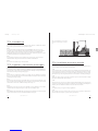
TC 6.2
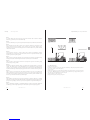
For proper air circulation, verify that the installation environment provides adequate free volumes and air passages
suitable to the airflow and air throw of the unit. Otherwise the declared performance may not be guaranteed and
operating defects may occur. Be careful not to block the inlet or the outlet air flow of the fanmotors and the heat
exchangers (see fig.3).
TC 6.3
Check that the support structures and anchoring devices comply with the weight and shape of the unit (see chapters
Dimensions and Technical Data).
TC 6.4
Fix the unit to all provided fixing points (see chapter Dimensions) with adequate anchors in accordance with the total
weight that it could reach (net weight of the unit, weight of the refrigerant, weight of any ice accumulation on the heat
exchanger, weight of any accumulation in the drip trays).
TC 6.5
The unit is not designed to support additional loads.
TC 6.6
In models with electric defrost option, make sure to guarantee or provide adequate space to allow the replacement of
the heating elements in the heat exchangers.
fig.1 - For safe handling the forks must always
protrude from the wooden cage.
TC 6. Installation and commissioning

Heat Exchange SolutionsThermoKey Technical Manual TC Instruction and technical data
1211
EN
MT TC A DF EN 04 2017MT TC A DF EN 04 2017
TC 6.7
In environments with multiple units no alternating defrosting cycles should be carried out, in order to avoid the
abnormal formation of frost on the heat exchangers.
TC 6.8
Check that the power line is compliant with the requirements of the unit shown on the technical data label.
TC 6.9
Before connecting the unit, verify the presence of disconnecting and breaking devices on the power supply line,
protection against electric shock, protection of equipment and any other device required by law. Standard models
are supplied with junction boxes for the supply of fanmotors and with junction boxes for the supply of the heating
elements in models with electric defrosting.
TC 6.10
If speed controls are used for the fanmotors, check their compatibility. Non-compliant devices may generate noise and
damage the fanmotors. The manufacturer does not guarantee the indicated performance of units equipped with speed
controllers.
TC 6.11
Verify that the line of the refrigerant is adequate for the performance of the unit. When connecting the cooling circuit,
do not deform the capillaries and do not change the position of the distributor or the manifolds in general.
TC 6.12
Verify that the operating condition limits (humidity, temperature and pressure) meet the specific requirements of the
product selection.
TC 6.13
For units with electrical defrosting and, depending on the type of cold room, correctly dene the time and the number of
defrosting cycles. e defrosting cycle must be controlled with a chrono-thermostat and the temperature probes should
not stop the defrosting cycle prematurely but only prevent overheating. e probes must be placed in the coldest parts
of the heat exchanger (where there is the greatest frost formation) and at a distance from the heating elements.
TC 6.14
Make sure that at the end of each defrosting cycle (electric, hot gas or warm glycol), the finned pack, the internal
drip tray and the drain dischargers are clean. If necessary, correct the timing and the number of the defrosting cycles.
Accumulations of frost tend to turn into harmful ice accumulations that may cause malfunctioning or the failure of
the heat exchanger.
TC 6.15
Install the appropriate siphons on the drain discharge line and verify their effectiveness at all operating temperatures.
In low temperature rooms functioning below the freezing point, the external moisture entering from the discharge
line, if not provided with siphons, generates harmful ice accumulations.
TC 6.16
Access to the installed unit, for any type of intervention, should be reserved to experienced personnel specically trained to
run the system, in compliance with current regulations.
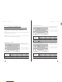
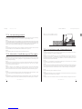
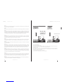
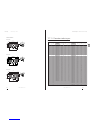
fig.2 – Fixing sequence:
a) Remove the top of the wooden cage.
b) Possible easy installation sequence only for standard models with up to maximum two fanmotors, remove also the sides
and the ends of the wooden cage.
c) Lift and position.
d) Fix the unit to all appropriate points (see chapter dimensions) with adequate anchors in accordance with the total
weight (net weight of the unit, weight of the refrigerant, weight of any ice accumulation on the heat exchanger, weight of
any accumulation in the drip trays).
e) Remove the wooden cage and the transport brackets.
f) Remove the bottom of the wooden cage and the transport brackets.
c) e d)
c) e d)
a) e b)
e) f)
a)

Heat Exchange SolutionsThermoKey Technical Manual TC Instruction and technical data
1413
EN
MT TC A DF EN 04 2017MT TC A DF EN 04 2017
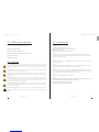
TC 7. General maintenance and overall control
TC 7.1
Before performing any maintenance, make sure that the power supply of the unit has been sectioned off: the
electrical parts may be connected to automatic controls. All maintenance operations must be carried out by
qualified and experienced personnel.
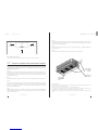
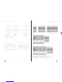
TC 7.2
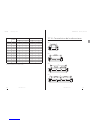
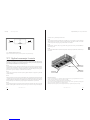
The unit mainly consists of: a finned pack heat exchanger, a structural frame in metal sheet panels, metal sheet covers,
accessible drip trays and fanmotors. In units with electric defrosting, stainless steel armoured heating elements with
vulcanised terminals are enclosed in the heat exchanger and mounted on the drip trays with locking devices that
prevent displacement (see fig.4).
TC 7.3
Periodically check the fixing points of the unit, the electrical connections and the connections to the refrigerant line.
TC 7.4
Provide for periodic cleaning of the casing and the exchanger using suitable detergents or possibly water with neutral
pH soap. Do not use aggressive cleaning agents, solvents, acids or basic solutions containing chlorine or ammonia.
Avoid the use of abrasives in general. In case of use of sanitising agents, check their compatibility with the materials.
If in doubt, contact the Manufacturer.
TC 7.5
Check the effectiveness of defrosting. For units with electric defrosting, periodically check the operation of all heating
elements. The Manufacturer will not respond in any way for damages and defects caused by undetected malfunctions
(eg. harmful ice accumulations).
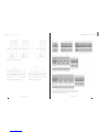
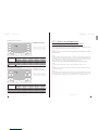
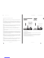
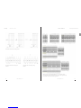
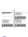
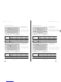
fig.3 – Minimum distance from walls
N.B.: Be careful not to block the inlet or the outlet air flow of the fanmotors and the heat exchangers.
<< MIN. 1m >> << MIN. 1m >>
TC 7.6
Provide for the replacement of faulty heating elements. Pay special attention during installation to prevent damage to
vulcanised insulations; properly restore all connections (see enclosed diagrams) and all locking systems to prevent the
displacement of the same during operation.
TC 7.7
Inspection and maintenance intervals depend on the type of cell, therefore they need to be defined by qualified and
experienced personnel.
TC 7.8
For any operation on the unit not described in this manual, please contact the Manufacturer.
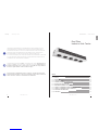
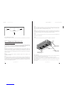
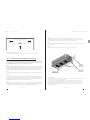
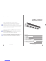
fig.4 – Components
a) The front covers are removable to facilitate access to the manifolds compartment during the installation and maintenance
phases. The closing covers are assured by screws.
b) The lower covers are removable to allow full access to the manifolds compartment.
c) The drip trays are fitted with hinges for easy access to the internal drip tray to allow replacement of the defrosting
heating elements or for cleaning operations. They can be disassembled if replacement is needed.
d) Each fanmotor is equipped with a structural guard grille wich allows replacement operations completely from the
outside.
REMOVABLE
LOWER COVERS
FRONT COVERS
THAT CAN BE
OPENED
HINGED
EXTERNAL DRIP
TRAYS
FANMOTORS

Heat Exchange SolutionsThermoKey Technical Manual TC Instruction and technical data
1615
EN
MT TC A DF EN 04 2017MT TC A DF EN 04 2017
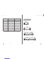
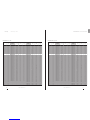
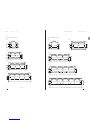
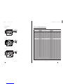
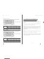
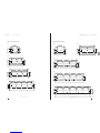
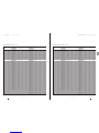
TC 8. Wiring diagrams and power rating of
electric heaters
TC 8.1
The casing of each unit is equipped with ground terminal (PE) with an identification label.
It is mandatory to connect the ground terminal of the unit to the external protective conductor or earthing
system.
TC 8.2
It is mandatory to use protection systems against electric shock and equipment protection devices on the supply lines
of the defrosting heaters.
TC 8.3
Periodically check the efficiency of all electric heaters to prevent the unit from forming dangerous ice accumulations
caused by any undetected malfunctions.
DFX DFB DFN DFC Ø 500 mm 04 RR
SUPPLY LINE ~3 400V 50-60HZ
STAR CONNECTION WITH NEUTRAL
Coil power
Drip tray power
Total power
3400
1700
5100
6800
3400
10200
10200
5100
15300
13600
6800
20400
150 45 04
150 70 04
150 10 04
250 45 04
250 70 04
250 10 04
350 45 04
350 70 04
350 10 04
450 45 04
450 70 04
450 10 04
MODELS
DFX DFB DFN DFC
(W)
(W)
(W)
HTH1
HTH2
HTH3
HTH4
HTL1 HTL3HTL2 HTL4
PE
HTH = High power electric heater (*) HTL = Low power electric heater (*)
(*) The HTH High power heater has twice the power of the low power heater HTL
Coil power
Drip tray power
Total power
5950
1700
7650
11900
3400
15300
17850
5100
22950
23800
6800
30600
150 45 08
150 70 08
150 10 08
250 45 08
250 70 08
250 10 08
350 45 08
350 70 08
350 10 08
450 45 08
450 70 08
450 10 08
MODELS
DFX DFB DFN DFC
(W)
(W)
(W)
Coil power
Drip tray power
Total power
3400
1700
5100
6800
3400
10200
10200
5100
15300
13600
6800
20400
150 45 06
150 70 06
150 10 06
250 45 06
250 70 06
250 10 06
350 45 06
350 70 06
350 10 06
450 45 06
450 70 06
450 10 06
MODELS
DFX DFB DFN DFC
(W)
(W)
(W)
DFX DFB DFN DFC Ø 500 mm 06 RR
DFX DFB DFN DFC Ø 500 mm 08 RR
HTH = High power electric heater (*) HTL = Low power electric heater (*)
(*) The HTH High power heater has twice the power of the low power heater HTL
HTH = High power electric heater (*) HTL = Low power electric heater (*)
(*) The HTH High power heater has twice the power of the low power heater HTL
SUPPLY LINE ~3 400V 50-60HZ
STAR CONNECTION WITH NEUTRAL
SUPPLY LINE ~3 400V 50-60HZ
STAR CONNECTION WITH NEUTRAL
HTH1
HTL1
HTL3
HTL2
HTL4
HTH2
HTL5 HTL7HTL6 HTL8
HTH1
HTH3
HTL2
HTL1
HTH6
HTH5
HTL3 HTL5HTL4 HTL6
HTH4HTH2
PE
PE

Heat Exchange SolutionsThermoKey Technical Manual TC Instruction and technical data
1817
EN
MT TC A DF EN 04 2017MT TC A DF EN 04 2017
DFX DFB DFN DFC Ø 560 mm 04 RR
DFX DFB DFN DFC Ø 560 mm 06 RR
SUPPLY LINE ~3 400V 50-60HZ
STAR CONNECTION WITH NEUTRAL
SUPPLY LINE ~3 400V 50-60HZ
STAR CONNECTION WITH NEUTRAL
HTH1 HTH2
HTL1 HTL3
HTL2 HTL4
HTL5 HTL7HTL6 HTL8
HTH1 HTH4
HTH2 HTH5
HTH3 HTH6
HTL1 HTL2
HTL3 HTL5HTL4 HTL6
PE
PE
Coil power
Drip tray power
Total power
3400
1700
5100
6800
3400
10200
10200
5100
15300
13600
6800
20400
156 45 04
156 70 04
156 10 04
256 45 04
256 70 04
256 10 04
356 45 04
356 70 04
356 10 04
456 45 04
456 70 04
456 10 04
MODELS
DFX DFB DFN DFC
(W)
(W)
(W)
HTH = High power electric heater (*) HTL = Low power electric heater (*)
(*) The HTH High power heater has twice the power of the low power heater HTL
Coil power
Drip tray power
Total power
5950
1700
7650
11900
3400
15300
17850
5100
22950
23800
6800
30600
156 45 06
156 70 06
156 10 06
256 45 06
256 70 06
256 10 06
356 45 06
356 70 06
356 10 06
456 45 06
456 70 06
456 10 06
MODELS
DFX DFB DFN DFC
(W)
(W)
(W)
HTH = High power electric heater (*) HTL = Low power electric heater (*)
(*) The HTH High power heater has twice the power of the low power heater HTL
DFX DFB DFN DFC Ø 630 mm 04 RR
SUPPLY LINE ~3 400V 50-60HZ
STAR CONNECTION WITH NEUTRAL
SUPPLY LINE ~3 400V 50-60HZ
STAR CONNECTION WITH NEUTRAL
Coil power
Drip tray power
Total power
8500
1700
10200
17000
3400
20400
25500
5100
30600
34000
6800
40800
156 45 08
156 70 08
156 10 08
256 45 08
256 70 08
256 10 08
356 45 08
356 70 08
356 10 08
456 45 08
456 70 08
456 10 08
MODELS
DFX DFB DFN DFC
(W)
(W)
(W)
HTH = High power electric heater (*) HTL = Low power electric heater (*)
(*) The HTH High power heater has twice the power of the low power heater HTL
HTH = High power electric heater (*) HTL = Low power electric heater (*)
(*) The HTH High power heater has twice the power of the low power heater HTL
DFX DFB DFN DFC Ø 560 mm 08 RR
HTH1 HTH5
HTL2 HTL4
HTH2 HTH6
HTH3
HTL3
HTH4
HTH7
HTL1
HTH8
HTL5 HTL7HTL6 HTL8
PE
HTH1
HTL2
HTL1
HTH2
HTL4
HTL3
HTL5 HTL7HTL6 HTL8
PE
Coil power
Drip tray power
Total power
3680
1840
5520
7360
3680
11040
11040
5520
16560
14720
7360
22080
18400
9200
27600
163 45 04
163 70 04
163 10 04
263 45 04
263 70 04
263 10 04
363 45 04
363 70 04
363 10 04
463 45 04
463 70 04
463 10 04
563 45 04
563 70 04
563 10 04
MODELS
DFX DFB DFN DFC
(W)
(W)
(W)

Heat Exchange SolutionsThermoKey Technical Manual TC Instruction and technical data
2019
EN
MT TC A DF EN 04 2017MT TC A DF EN 04 2017
DFX DFB DFN DFC Ø 630 mm 06 RR
DFX DFB DFN DFC Ø 630 mm 08 RR
HTH = High power electric heater (*) HTL = Low power electric heater (*)
(*) The HTH High power heater has twice the power of the low power heater HTL
HTH = High power electric heater (*) HTL = Low power electric heater (*)
(*) The HTH High power heater has twice the power of the low power heater HTL
Coil power
Drip tray power
Total power
9200
1840
11040
18400
3680
22080
27600
5520
33120
36800
7360
44160
46000
9200
55200
163 45 08
163 70 08
163 10 08
263 45 08
263 70 08
263 10 08
363 45 08
363 70 08
363 10 08
463 45 08
463 70 08
463 10 08
563 45 08
563 70 08
563 10 08
MODELS
DFX DFB DFN DFC
(W)
(W)
(W)
Coil power
Drip tray power
Total power
6440
1840
8280
12880
3680
16560
19320
5520
24840
25760
7360
33120
32200
9200
41400
163 45 06
163 70 06
163 10 06
263 45 06
263 70 06
263 10 06
363 45 06
363 70 06
363 10 06
463 45 06
463 70 06
463 10 06
563 45 06
563 70 06
563 10 06
MODELS
DFX DFB DFN DFC
(W)
(W)
(W)
HTH1 HTH5
HTL2 HTL4
HTH2 HTH6
HTH3
HTL3
HTH4
HTH7
HTL1
HTH8
HTL5 HTL7HTL6 HTL8
PE
HTH1 HTH4
HTH2 HTH5
HTH3 HTH6
HTL1 HTL2
HTL3 HTL5HTL4 HTL6
PE
SUPPLY LINE ~3 400V 50-60HZ
STAR CONNECTION WITH NEUTRAL
SUPPLY LINE ~3 400V 50-60HZ
STAR CONNECTION WITH NEUTRAL
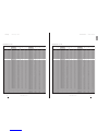
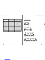
TC 9. Wiring and absorption diagrams
of fanmotors
TC 9.1
The casing of each unit is equipped with a ground terminal (PE9) with an identification label. It is mandatory to
connect the ground terminal of the unit to the external conductor or protective earthing system.
TC 9.2
In the units with wired fanmotors it is mandatory to connect the protective conductors of the fanmotors to the external
conductor or protective earthing system.
TC 9.3
It is mandatory to use protection systems against electric shock and equipment protection devices on the supply
lines of the fanmotors. The fanmotors are equipped with thermal contacts normal closed inserted in the windings
of the motor. Connect the thermal contacts to protect the engine from overheating. Please be aware that an over-
temperature can also be not directly caused by an overcurrent.
Please be aware that the thermal contact closes itself when the temperature decreases without a manual reset.
TC 9.4
Strictly follow the wiring diagrams to avoid damaging the motors (a,b,c,d,e).
TC 9.5
For models fitted with non standard fanmotors please refer to the diagrams and absorptions indicated in the
supplementary sheets and the rating plate.
TC 9.6
Before using any fanmotor speed control system check its compatibility with the fanmotors. Non-compatible systems
may generate noise and damages. The Manufacturer does not accept any responsibility regarding the performance of
the units equipped with speed controllers not defined during the offer.

Heat Exchange SolutionsThermoKey Technical Manual TC Instruction and technical data
2221
EN
MT TC A DF EN 04 2017MT TC A DF EN 04 2017
a) Standard fanmotor connection schemes
b) Fanmotor Delta connection (high speed) c) Fanmotor Star connection (low speed)
d) Terminal blocks scheme of the main electrical box from 1 up to 5 fanmotors.
Supply parallel connected and thermal contacts series connected (ready to use).
Single connection available with jumper removing.

547
250 250
577
1004 FIXING
1511
547
250 250
577
2004 FIXING
2511
547
250 250
577
3004
2002 FIXING 1002 FIXING
3511
Heat Exchange SolutionsThermoKey Technical Manual TC Instruction and technical data
2423
EN
MT TC A DF EN 04 2017MT TC A DF EN 04 2017
1
2
3
4
1
2
3
4
1
2
3
4
5
500
500
500
500
560
560
560
560
630
630
630
630
630
NO. OF
MOTORS
NOMINAL
DIAMETER
0,77
1,54
2,31
3,08
1,05
2,10
3,15
4,20
1,25
2,50
3,75
5,00
6,25
1,7
3,4
5,1
6,8
2,2
4,4
6,6
8,8
2,48
4,96
7,44
9,92
12,4
HIGH SPEED
KW A
0,49
0,98
1,47
1,96
0,58
1,16
1,74
2,32
0,84
1,68
2,52
3,36
4,20
0,84
1,68
2,52
3,36
1,1
2,2
3,3
4,4
1,42
2,84
4,26
5,68
7,10
KW A
LOW SPEED
e) standard fanmotor nominal absorptions
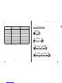
TC 10. Dimensions
DFX DFB DFN DFC Ø 500 mm
1X500
2X500
3X500
4X500
547
4004250 250
577
4511
2002 FIXING2002 FIXING

776
748
300 300
1004 FIXING
1611
776
748
2004300 300
1002 FIXING 1002 FIXING
2611
776
748
3004300 300
1002 FIXING 1000 FIXING 1002 FIXING
3612
776
748
4004300 300
1002 FIXING 1000 FIXING 1000 FIXING 1002 FIXING
4612
804
767
2404300 300
1202 FIXING 1202 FIXING
3013
Heat Exchange SolutionsThermoKey Technical Manual TC Instruction and technical data
2625
EN
MT TC A DF EN 04 2017MT TC A DF EN 04 2017
DFX DFB DFN DFC Ø 560 mm
1X560
2X560
3X560
4X560
DFX DFB DFN DFC Ø 630 mm
804
767
300 300
1204 FIXING
1812
1X630 2X630
804
767
3604300 300
1202 FIXING 1200 FIXING 1202 FIXING
4212
3X630
804
767
4804300 300
1202 FIXING 1200 FIXING 1200 FIXING 1202 FIXING
5412
4X630
804
767
6004 300 300
1202 FIXING 1200 FIXING 1200 FIXING 1200 FIXING 1202 FIXING
6613
5X630

1810
449
1656
50
661
1746 FIXING
1960
1896 FIXING
50
863
470
1808
1960
1896 FIXING
50
886
470
1808
Heat Exchange SolutionsThermoKey Technical Manual TC Instruction and technical data
2827
EN
MT TC A DF EN 04 2017MT TC A DF EN 04 2017
DFX DFB DFN DFC
Ø 500 mm
Ø 560 mm
Ø 630 mm
TC 11. Technical Data
1
1
1
2
2
2
3
3
3
4
4
4
1
1
1
2
2
2
3
3
3
4
4
4
1
1
1
2
2
2
3
3
3
4
4
4
5
5
5
500
500
500
500
500
500
500
500
500
500
500
500
560
560
560
560
560
560
560
560
560
560
560
560
560
630
630
630
630
630
630
630
630
630
630
630
630
630
630
60,57
90,85
121,40
121,14
181,70
242,80
181,71
272,55
364,20
242,28
363,40
485,60
90,85
136,28
181,71
181,70
272,56
363,42
272,55
408,84
545,13
363,40
545,12
726,84
109,02
163,54
218,05
218,04
327,08
436,10
327,06
490,62
654,15
436,08
654,16
872,20
/
/
/
7,2
10,7
14,3
14,4
21,4
28,6
21,6
32,1
42,9
28,8
42,8
57,2
10,9
16,3
21,7
21,8
32,6
43,4
32,7
48,9
65,1
43,6
65,2
86,8
12,9
19,3
25,8
25,8
38,6
51,6
38,7
57,9
77,4
51,6
77,2
103,2
/
/
/
58,76
88,15
117,53
117,52
176,30
235,06
176,28
264,45
352,59
235,04
352,60
470,12
88,15
132,22
176,29
176,30
264,44
352,58
264,45
396,66
528,87
352,60
528,88
705,16
105,77
158,66
211,55
211,54
317,32
423,10
317,31
475,98
634,65
423,08
634,64
846,20
528,85
793,30
1057,75
12,7
19,1
25,4
25,4
38,2
50,8
38,1
57,3
76,2
50,8
76,4
101,6
19,1
28,6
38,1
38,2
57,2
76,2
57,3
85,8
114,3
76,4
114,3
76,4
114,4
152,4
22,9
34,3
45,7
45,8
68,6
91,4
68,7
102,9
137,2
182,8
114,5
171,5
228,5
104
118
131
190
216
241
274
312
352
358
409
462
148
168
198
257
297
348
361
425
488
467
553
632
169
192
226
287
333
392
401
474
546
516
615
705
638
770
875
104
118
131
190
216
241
274
312
352
358
409
462
148
168
198
257
297
348
361
425
488
467
553
632
169
192
226
287
333
392
401
474
546
516
615
705
/
/
/
DFX1504504
DFX1504506
DFX1504508
DFX2504504
DFX2504506
DFX2504508
DFX3504504
DFX3504506
DFX3504508
DFX4504504
DFX4504506
DFX4504508
DFX1564504
DFX1564506
DFX1564508
DFX2564504
DFX2564506
DFX2564508
DFX3564504
DFX3564506
DFX3564508
DFX4564504
DFX4564506
DFX4564508
DFX1634504
DFX1634506
DFX1634508
DFX2634504
DFX2634506
DFX2634508
DFX3634504
DFX3634506
DFX3634508
DFX4634504
DFX4634506
DFX4634508
/
/
/
DFB1504504
DFB1504506
DFB1504508
DFB2504504
DFB2504506
DFB2504508
DFB3504504
DFB3504506
DFB3504508
DFB4504504
DFB4504506
DFB4504508
DFB1564504
DFB1564506
DFB1564508
DFB2564504
DFB2564506
DFB2564508
DFB3564504
DFB3564506
DFB3564508
DFB4564504
DFB4564506
DFB4564508
DFB1634504
DFB1634506
DFB1634508
DFB2634504
DFB2634506
DFB2634508
DFB3634504
DFB3634506
DFB3634508
DFB4634504
DFB4634506
DFB4634508
DFB5634504
DFB5634506
DFB5634508
Mot.
n°
Dia
[mm] MODEL
External
Surface
[m2]
External
Surface
[m2]
Internal
Volume
[dm3]
Internal
Volume
[dm3]
Net
Weight
[kg]
Net
Weight
[kg]
MODEL
DFX DFB PITCH 4,5 mm
32
70
18x30
32
70
18x30
32
70
18X30

Heat Exchange SolutionsThermoKey Technical Manual TC Instruction and technical data
3029
EN
MT TC A DF EN 04 2017MT TC A DF EN 04 2017
DFX DFB PITCH 10,0 mmDFX DFB PITCH 7,0 mm
1
1
1
2
2
2
3
3
3
4
4
4
1
1
1
2
2
2
3
3
3
4
4
4
1
1
1
2
2
2
3
3
3
4
4
4
5
5
5
500
500
500
500
500
500
500
500
500
500
500
500
560
560
560
560
560
560
560
560
560
560
560
560
560
630
630
630
630
630
630
630
630
630
630
630
630
630
630
DFX1507004
DFX1507006
DFX1507008
DFX2507004
DFX2507006
DFX2507008
DFX3507004
DFX3507006
DFX3507008
DFX4507004
DFX4507006
DFX4507008
DFX1567004
DFX1567006
DFX1567008
DFX2567004
DFX2567006
DFX2567008
DFX3567004
DFX3567006
DFX3567008
DFX4567004
DFX4567006
DFX4567008
DFX1637004
DFX1637006
DFX1637008
DFX2637004
DFX2637006
DFX2637008
DFX3637004
DFX3637006
DFX3637008
DFX4637004
DFX4637006
DFX4637008
/
/
/
39,84
59,76
79,68
79,68
119,52
159,36
119,52
179,28
239,04
159,36
239,04
318,72
59,76
89,64
119,53
119,52
179,28
239,06
179,28
268,92
358,59
239,04
358,56
478,12
71,72
107,57
143,43
143,44
215,14
286,86
215,16
322,71
430,29
286,88
430,28
573,72
/
/
/
7,2
10,7
14,3
14,4
21,4
28,6
21,6
32,1
42,9
28,8
42,8
57,2
10,9
16,3
21,7
21,8
32,6
43,4
32,7
48,9
65,1
43,6
65,2
86,8
12,9
19,3
25,8
25,8
38,6
51,6
38,7
57,9
77,4
51,6
77,2
103,2
/
/
/
102
115
127
186
210
234
268
304
341
351
399
448
144
164
192
248
289
331
352
412
470
455
537
609
165
187
219
277
323
372
390
460
526
502
596
679
/
/
/
38,97
58,45
77,94
77,94
116,90
155,88
116,91
175,35
233,82
155,88
233,80
311,76
58,45
87,68
116,91
116,90
175,36
233,82
175,35
263,04
350,73
233,80
350,72
467,64
70,14
105,22
140,29
140,28
210,44
280,58
210,42
315,66
420,87
280,56
420,88
561,16
350,70
526,10
701,45
102
115
127
186
210
234
268
304
341
351
399
448
144
164
192
248
289
331
352
412
470
455
537
609
165
187
219
277
323
372
390
460
526
502
596
679
620
746
842
DFB1507004
DFB1507006
DFB1507008
DFB2507004
DFB2507006
DFB2507008
DFB3507004
DFB3507006
DFB3507008
DFB4507004
DFB4507006
DFB4507008
DFB1567004
DFB1567006
DFB1567008
DFB2567004
DFB2567006
DFB2567008
DFB3567004
DFB3567006
DFB3567008
DFB4567004
DFB4567006
DFB4567008
DFB1637004
DFB1637006
DFB1637008
DFB2637004
DFB2637006
DFB2637008
DFB3637004
DFB3637006
DFB3637008
DFB4637004
DFB4637006
DFB4637008
DFB5637004
DFB5637006
DFB5637008
Mot.
n°
Dia
[mm] MODEL
1
1
1
2
2
2
3
3
3
4
4
4
1
1
1
2
2
2
3
3
3
4
4
4
1
1
1
2
2
2
3
3
3
4
4
4
5
5
5
500
500
500
500
500
500
500
500
500
500
500
500
560
560
560
560
560
560
560
560
560
560
560
560
560
630
630
630
630
630
630
630
630
630
630
630
630
630
630
DFX1501004
DFX1501006
DFX1501008
DFX2501004
DFX2501006
DFX2501008
DFX3501004
DFX3501006
DFX3501008
DFX4501004
DFX4501006
DFX1001008
DFX1561004
DFX1561006
DFX1561008
DFX2561004
DFX2561006
DFX2561008
DFX3561004
DFX3561006
DFX3561008
DFX4561004
DFX4561006
DFX4561008
DFX1631004
DFX1631006
DFX1631008
DFX2631004
DFX2631006
DFX2631008
DFX3631004
DFX3631006
DFX3631008
DFX4631004
DFX4631006
DFX4631008
/
/
/
28,65
42,97
57,30
57,30
85,94
114,60
85,95
128,91
171,90
114,60
171,88
229,20
42,97
64,46
85,95
85,94
128,92
171,90
128,91
193,38
257,85
171,88
257,84
343,80
51,57
77,35
103,14
103,14
154,70
206,28
154,71
232,05
309,42
206,28
309,40
412,56
/
/
/
7,2
10,7
14,3
14,4
21,4
28,6
21,6
32,1
42,9
28,8
42,8
57,2
10,9
16,3
21,7
21,8
32,6
43,4
32,7
48,9
65,1
43,6
65,2
86,8
12,9
19,3
25,8
25,8
38,6
51,6
38,7
57,9
77,4
51,6
77,2
103,2
/
/
/
101
113
125
184
206
229
264
298
333
347
391
437
142
160
187
243
281
322
344
402
457
446
524
593
162
183
214
272
315
362
382
449
511
492
581
660
/
/
/
28,28
42,42
56,56
56,56
84,84
113,12
84,84
127,26
169,68
113,12
169,68
226,24
42,42
63,63
84,84
84,84
127,26
169,68
127,26
190,89
254,52
169,68
254,52
339,36
50,90
76,35
101,81
101,80
152,70
203,62
152,70
229,05
305,43
203,60
305,40
407,24
254,50
381,75
509,05
12,7
19,1
25,4
25,4
38,2
50,8
38,1
57,3
76,2
50,8
76,4
101,6
19,1
28,6
38,1
38,2
57,2
76,2
57,3
85,8
114,3
76,4
114,4
152,4
22,9
34,3
45,7
45,8
68,6
91,4
68,7
102,9
137,2
91,6
137,2
182,8
114,5
171,5
228,5
12,7
19,1
25,4
25,4
38,2
50,8
38,1
57,3
76,2
50,8
76,4
101,6
19,1
28,6
38,1
38,2
57,2
76,2
57,3
85,8
114,3
76,4
114,4
152,4
22,9
34,3
45,7
45,8
68,6
91,4
68,7
102,9
137,2
91,6
137,2
182,8
114,5
171,5
228,5
101
113
125
184
206
229
264
298
333
347
391
437
142
160
187
243
281
322
344
402
457
446
524
593
162
183
214
272
315
362
382
449
511
492
581
660
607
727
817
DFB1501004
DFB1501006
DFB1501008
DFB2501004
DFB2501006
DFB2501008
DFB3501004
DFB3501006
DFB3501008
DFB4501004
DFB4501006
DFB1001008
DFB1561004
DFB1561006
DFB1561008
DFB2561004
DFB2561006
DFB2561008
DFB3561004
DFB3561006
DFB3561008
DFB4561004
DFB4561006
DFB4561008
DFB1631004
DFB1631006
DFB1631008
DFB2631004
DFB2631006
DFB2631008
DFB3631004
DFB3631006
DFB3631008
DFB4631004
DFB4631006
DFB4631008
DFB5631004
DFB5631006
DFB5631008
Mot.
n°
Dia
[mm] MODEL
External
Surface
[m2]
External
Surface
[m2]
Internal
Volume
[dm3]
Internal
Volume
[dm3]
Net
Weight
[kg]
Net
Weight
[kg]
MODEL
External
Surface
[m2]
External
Surface
[m2]
Internal
Volume
[dm3]
Internal
Volume
[dm3]
Net
Weight
[kg]
Net
Weight
[kg]
MODEL


Heat Exchange SolutionsThermoKey Manuale Tecnico TC Istruzioni e dati tecnici
3332
IT
MT TC A DF IT 04 2017MT TC A DF IT 04 2017
LEGGERE ATTENTAMENTE E COMPRENDERE COMPLETAMENTE TUTTE
LE INFORMAZIONI CONTENUTE IN QUESTE ISTRUZIONI PRIMA DELLA
PROGETTAZIONE ED IN OGNI CASO PRIMA DI EFFETTUARE QUALUNQUE
OPERAZIONE DI MOVIMENTAZIONE, DISIMBALLAGGIO, MONTAGGIO,
POSIZIONAMENTO E MESSA IN ESERCIZIO DELL’APPARECCHIO.
IL COSTRUTTORE DECLINA OGNI RESPONSABILITÀ PER DANNI A PERSONE
O COSE DERIVANTI DALLA MANCATA OSSERVANZA DELLE INDICAZIONI
CONTENUTE NEL PRESENTE DOCUMENTO.
L’originale del presente manuale è in italiano , ed è reperibile sul sito internet: www.thermokey.com.
La traduzione in inglese è conforme all’originale ed è reperibile sul sito internet: www.thermokey.com.
Le traduzioni in altre lingue possono contenere errori; in caso di dubbio fare sempre riferimento
alla versione originale in italiano od alla sua traduzione in inglese.
Il sistema di gestione Qualità della ThermoKey è certificato in conformità alla norma ISO 9001,
il Sistema di Gestione Ambiente è certificato in conformità alla norma ISO 14001 e il Sistema di
Gestione Sicurezza è certificato in conformità alla norma OHSAS 18001.
Dual Flow
Industrial Unit Cooler
TC 1. RIFERIMENTI NORMATIVI
TC 2. PERICOLI
TC 3. AVVERTENZE
TC 4. DESTINAZIONE D’USO
TC 5. ISPEZIONE, MOVIMENTAZIONE E TRASPORTO
TC 6. INSTALLAZIONE E MESSA IN OPERA
TC 7. MANUTENZIONE GENERALE E CONTROLLO
TC 8. SCHEMI DI COLLEGAMENTO DELLE RESISTENZE DI SBRINAMENTO
TC 9. SCHEMI DI COLLEGAMENTO DEI MOTOVENTILATORI
TC 10. CARATTERISTICHE DIMENSIONALI
TC 11. DATI TECNICI
INDICE
34
34
35
36
36
37
40
42
46
51
55

Heat Exchange SolutionsThermoKey Manuale Tecnico TC Istruzioni e dati tecnici
3534
IT
MT TC A DF IT 04 2017MT TC A DF IT 04 2017
Pericolo di elettrocuzione. Il prodotto è allestito con elettroventilatori ed eventuali resistestenze elettriche di sbrinamento
con tensione nominale di funzionamento in bassa tensione trifase e monofase. Le linee di alimentazione elettrica dovranno
utilizzare i sistemi di protezione contro la scossa elettrica e di protezione dell’equipaggiamento previsti dalla normativa
vigente.
Pericolo di ustione. Nei prodotti allestiti con resistenze elettriche di sbrinamento le temperature superficiali delle corazze,
se lasciate accese senza controllo, possono raggiungere i 350°C.
Pericolo di taglio. Lo scambiatore di calore, parte integrante del prodotto, è costituito da alette metalliche con bordi
taglienti, non protette. La carrozzeria è costituita da componenti in lamiera che in alcuni punti possono presentare bordi
taglienti non protetti.
Pericolo parti in movimento. Il prodotto è allestito con elettroventilatori dotati di griglia di protezione secondo
quanto previsto dalla normativa vigente. Per alcuni prodotti potrebbe essere possibile accedere volutamente alle parti
in movimento (pale dei motoventilatori) da zone non protette. Prima di qualsiasi accesso assicurarsi che le parti
in movimento non possano costituire pericolo agli operatori.
Pericolo di schiacciamento degli arti o della persona. Durante le fasi di movimentazione, trasporto ed installazione,
funzionamento e manutenzione, porre la massima attenzione al peso indicato di ogni prodotto per evitare ribaltamenti
o cadute pericolose verso gli operatori.
Pericolo di caduta oggetti. I prodotti sono provvisti di porte, vaschette o lamierati di tamponamento che in fase di
installazione o di manutenzione possono essere smontate rimuovendo le viti di fissaggio previste, prendere le opportune
precauzioni.
TC 2. Pericoli
TC 1. Riferimenti Normativi
Il prodotto descritto in questo manuale risulta conforme alla:
DIRETTIVA MACCHINE 2006/42/EC
DIRETTIVA BASSA TENSIONE 2014/35/EU
DIRETTIVA COMPATIBILITA' ELETTROMAGNETICA 2014/30/EU
DIRETTIVA PED 2014/68/EU
DIRETTIVA ErP 2009/125/EC
TC 3. Avvertenze
TC 3.1
Contenuto del Manuale Tecnico di prodotto:
ISTRUZIONI GENERALI PER UN USO SICURO (IG)
ISTRUZIONI PER LA MOVIMENTAZIONE ED IL DISIMBALLO (IM)
ISTRUZIONI E DATI TECNICI (TC)
ISTRUZIONI SPECIFICHE D’USO E MANUTENZIONE (IS)
TC 3.2
Questo manuale è la sezione TC denominata ISTRUZIONI E DATI TECNICI del Manuale Tecnico di prodotto.
Per qualsiasi informazione non contemplata nel presente manuale fare riferimento alle altre sezioni (IG–IM–IS) e in
caso di dubbio contattare il Costruttore.
TC 3.3
Questo manuale è parte integrante dei modelli DFX DFB DFN e DFC e come tale deve essere conservato per tutto il
periodo di vita del prodotto.
TC 3.4
Eventuale documentazione tecnica supplementare relativa ai prodotti non standard è allegata al presente manuale, è
integrante ed è codificata con codice specifico indicato sui documenti di spedizione.
TC 3.5
Il prodotto descritto in questo manuale è considerato una quasi-macchina quindi non utilizzabile così come fornito
ma è un componente per impianti di condizionamento o refrigerazione e deve essere installato e messo in servizio solo
da operatori qualificati (vedere capitolo relativo ad installazione e messa in opera).
TC 3.6
Ogni prodotto è corredato di Dichiarazione di Incorporazione CE.
TC 3.7
Ulteriore documentazione relativa al prodotto, costituita da cataloghi, guide e bollettini tecnici, è fornita
direttamente da Thermokey reperibile sul sito internet www.thermokey.com.
CATALOGHI – http://www.thermokey.com/Cataloghi.aspx
MANUALI – http://www.thermokey.com/Manuali.aspx

Heat Exchange SolutionsThermoKey Manuale Tecnico TC Istruzioni e dati tecnici
3736
IT
MT TC A DF IT 04 2017MT TC A DF IT 04 2017
TC 4. Destinazione d'uso
TC 4.1
Il modello deve essere utilizzato esclusivamente per lo scopo di seguito indicato altrimenti, l’uso è da considerarsi
improprio ed esonera il costruttore da qualsiasi responsabilità conseguente.
TC 4.2
Gli aeroevaporatori o aerorefrigeratori industriali della serie DFX DFB DFN e DFC sono progettati per essere utilizzati in
tutti i settori alimentari, nelle medie e grandi celle frigorifere o magazzini refrigerati, per la conservazione del prodotto
fresco e congelato e anche per il rarescamento e condizionamento di medie e grandi sale di lavorazione. Tutte le unità
standard sono equipaggiate con gruppo ventilante ad alta ecienza per un'ottimale distribuzione dell’aria.
TC 4.3
Il modello standard è equipaggiato con motoventilatori non adatti a sopportare prevalenze statiche aggiuntive come
quelle dovute a canalizzazioni, tunnel di abbattimento, etc..
TC 4.4
In caso di dubbio sulla destinazione d'uso contattare il Costruttore.
TC 5. Ispezione, movimentazione e trasporto
TC 5.1
Al ricevimento del modello controllare lo stato di integrità dell'imballaggio e del prodotto; contestare subito al
trasportatore qualsiasi danno eventuale verificatosi. L’imballaggio è fabbricato conformemente al modello, agli
adeguati mezzi di trasporto e di movimentazione.
TC 5.2
Durante il trasporto e la movimentazione del modello nel suo imballaggio, evitare sollecitazioni non conformi
e improprie sul prodotto imballato, attenersi a tutte le indicazioni illustrate e mantenere il modello sempre nella
posizione indicata in figura (Fig.1).
TC 5.3
Durante il trasporto e la movimentazione del prodotto imballato, utilizzare apposite protezioni per evitare di ferirsi
con le parti dell’imballaggio come chiodi, tavole o cartone e le parti del modello come le alette o la carrozzeria (vedi
DPI manuale tecnico sezione I cap IG 6).
TC 5.4
Disimballare il modello il più vicino possibile al luogo di installazione (vedi anche installazione e messa in opera). In
generale il modello non deve essere trasportato o movimentato privo dell’imballaggio originale.
TC 5.5
Durante la movimentazione per l'installazione del modello disimballato, utilizzare apposite protezioni per evitare di ferirsi
con le parti taglienti come le alette o la carrozzeria (vedi DPI manuale tecnico sezione I cap IG 6).
TC 6.1
L’installazione e la messa in opera del modello deve essere eseguita da personale esperto e qualificato. Per il fissaggio
seguire lo schema indicato in figura (Fig.2).
TC 6.2
Per una corretta circolazione dell’aria verificare che nell’ambiente di installazione siano garantiti volumi liberi e
passaggi dell’aria adeguati e conformi alle caratteristiche di portata e freccia d’aria del modello. Altrimenti potrebbero
non essere garantite le prestazioni dichiarate e generarsi difettosità di funzionamento. Attenzione a non ostruire né
l’aspirazione né la mandata dei motoventilatori e dello scambiatore (Fig.3).
TC 6.3
Verificare che le strutture di supporto e gli ancoraggi siano conformi al peso ed alla forma del modello (vedi capitoli
Caratteristiche dimensionali e Dati tecnici).
TC 6.4
Fissare il modello a tutti i punti previsti (vedi capitolo Caratteristiche dimensionali) con ancoraggi adeguati e conformi
al peso complessivo (peso netto del modello, peso del refrigerante, peso dell’eventuale accumulo di ghiaccio sullo
scambiatore, peso dell’eventuale accumulo nelle vaschette di raccolta condensa).
TC 6.5
Il modello non è progettato per supportare carichi aggiuntivi.
TC 6.6
Nei modelli con sbrinamento elettrico verificare che sia garantito o predisporre lo spazio adeguato per permettere la
sostituzione delle resistenze infilate negli scambiatori.
fig.1 - Per una movimentazione sicura le forche
devono sempre sporgere dall'imballaggio.
TC 6. Installazione e messa in opera
La pagina si sta caricando...
La pagina si sta caricando...
La pagina si sta caricando...
La pagina si sta caricando...
La pagina si sta caricando...
La pagina si sta caricando...
La pagina si sta caricando...
La pagina si sta caricando...
La pagina si sta caricando...
La pagina si sta caricando...
La pagina si sta caricando...
La pagina si sta caricando...
La pagina si sta caricando...
La pagina si sta caricando...
La pagina si sta caricando...
La pagina si sta caricando...
La pagina si sta caricando...
La pagina si sta caricando...
La pagina si sta caricando...
La pagina si sta caricando...
La pagina si sta caricando...
La pagina si sta caricando...
La pagina si sta caricando...
La pagina si sta caricando...
La pagina si sta caricando...
La pagina si sta caricando...
La pagina si sta caricando...
La pagina si sta caricando...
La pagina si sta caricando...
La pagina si sta caricando...
La pagina si sta caricando...
La pagina si sta caricando...
La pagina si sta caricando...
La pagina si sta caricando...
La pagina si sta caricando...
La pagina si sta caricando...
La pagina si sta caricando...
La pagina si sta caricando...
La pagina si sta caricando...
La pagina si sta caricando...
La pagina si sta caricando...
La pagina si sta caricando...
La pagina si sta caricando...
La pagina si sta caricando...
La pagina si sta caricando...
La pagina si sta caricando...
La pagina si sta caricando...
La pagina si sta caricando...
La pagina si sta caricando...
La pagina si sta caricando...
La pagina si sta caricando...
La pagina si sta caricando...
La pagina si sta caricando...
La pagina si sta caricando...
La pagina si sta caricando...
La pagina si sta caricando...
La pagina si sta caricando...
La pagina si sta caricando...
La pagina si sta caricando...
La pagina si sta caricando...
La pagina si sta caricando...
La pagina si sta caricando...
La pagina si sta caricando...
La pagina si sta caricando...
La pagina si sta caricando...
La pagina si sta caricando...
La pagina si sta caricando...
-
 1
1
-
 2
2
-
 3
3
-
 4
4
-
 5
5
-
 6
6
-
 7
7
-
 8
8
-
 9
9
-
 10
10
-
 11
11
-
 12
12
-
 13
13
-
 14
14
-
 15
15
-
 16
16
-
 17
17
-
 18
18
-
 19
19
-
 20
20
-
 21
21
-
 22
22
-
 23
23
-
 24
24
-
 25
25
-
 26
26
-
 27
27
-
 28
28
-
 29
29
-
 30
30
-
 31
31
-
 32
32
-
 33
33
-
 34
34
-
 35
35
-
 36
36
-
 37
37
-
 38
38
-
 39
39
-
 40
40
-
 41
41
-
 42
42
-
 43
43
-
 44
44
-
 45
45
-
 46
46
-
 47
47
-
 48
48
-
 49
49
-
 50
50
-
 51
51
-
 52
52
-
 53
53
-
 54
54
-
 55
55
-
 56
56
-
 57
57
-
 58
58
-
 59
59
-
 60
60
-
 61
61
-
 62
62
-
 63
63
-
 64
64
-
 65
65
-
 66
66
-
 67
67
-
 68
68
-
 69
69
-
 70
70
-
 71
71
-
 72
72
-
 73
73
-
 74
74
-
 75
75
-
 76
76
-
 77
77
-
 78
78
-
 79
79
-
 80
80
-
 81
81
-
 82
82
-
 83
83
-
 84
84
-
 85
85
-
 86
86
-
 87
87


ThermoKey DFC 150 10 06 Technical Manual
- Tipo
- Technical Manual
in altre lingue
- français: ThermoKey DFC 150 10 06
- polski: ThermoKey DFC 150 10 06