
CDC
MANUALE TECNICO
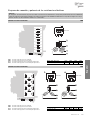
Aeroevaporatori a soffitto
BETRIEBSANLEITUNG
Deckenluftverdampfer
TECHNICAL MANUAL
Ceiling unit coolers
MANUAL TECNICO
Aeroevaporadores de techo
MANUEL TECHNIQUE
Evaporateurs plafonniers
ТЕХНИЧЕСКОЕ РУКОВОДСТВО
Потолочные воздухоохладители


1
www.modine.com
CDC
Indice
- Avvertenze . . . . . . . . . . . . . . . . . . . . . . . . . . . . . . . . . . . . . . . . . .2
- Ispezione - Trasporto . . . . . . . . . . . . . . . . . . . . . . . . . . . . . . . . . .2
- Condizioni da verificare per una corretta messa in opera . . . . . .2
- Manutenzione generale . . . . . . . . . . . . . . . . . . . . . . . . . . . . . . . .2
- Pericoli . . . . . . . . . . . . . . . . . . . . . . . . . . . . . . . . . . . . . . . . . . . . .2
- Norme di riferimento . . . . . . . . . . . . . . . . . . . . . . . . . . . . . . . . . .2
- Avvertenze per una corretta installazione . . . . . . . . . . . . . . . . . .3
- Suggerimenti per un corretto accesso all’apparecchio . . . . . . . .3
- Caratteristiche costruttive e dimensionali . . . . . . . . . . . . . . . . . .4
- Schema di collegamento dei motoventilatori . . . . . . . . . . . . . . . .5
- Schemi di collegamento e potenze delle resistenze elettriche . .6
- Garanzie . . . . . . . . . . . . . . . . . . . . . . . . . . . . . . . . . . . . . . . . . . .39
Index
- Hinweise . . . . . . . . . . . . . . . . . . . . . . . . . . . . . . . . . . . . . . . . . . . .8
- Kontrolle - Transport . . . . . . . . . . . . . . . . . . . . . . . . . . . . . . . . . .8
- Hinweise für eine korrekte Inbetriebnahme . . . . . . . . . . . . . . . . .8
- Allgemeine Wartung . . . . . . . . . . . . . . . . . . . . . . . . . . . . . . . . . . .8
- Gefahren . . . . . . . . . . . . . . . . . . . . . . . . . . . . . . . . . . . . . . . . . . .8
- Bezugsnormen . . . . . . . . . . . . . . . . . . . . . . . . . . . . . . . . . . . . . . .8
- Hinweise für eine korrekte Aufstellung . . . . . . . . . . . . . . . . . . . .9
- Ratschläge für einen korrekten Zugang zum Gerät . . . . . . . . . .9
- Konstruktionseigenschaften und Abmessungen . . . . . . . . . . . .10
- Anschlußplan der Motorventilatoren . . . . . . . . . . . . . . . . . . . . .11
- Anschlußplan und Leistungen der Heizstäbe . . . . . . . . . . . . . .12
- Gewährleistung . . . . . . . . . . . . . . . . . . . . . . . . . . . . . . . . . . . . .39
Index
- Important . . . . . . . . . . . . . . . . . . . . . . . . . . . . . . . . . . . . . . . . . .14
- Inspection - Transport . . . . . . . . . . . . . . . . . . . . . . . . . . . . . . . .14
- For a proper installation . . . . . . . . . . . . . . . . . . . . . . . . . . . . . . .14
- General maintenance . . . . . . . . . . . . . . . . . . . . . . . . . . . . . . . .14
- Hazards / Risks . . . . . . . . . . . . . . . . . . . . . . . . . . . . . . . . . . . . .14
- Reference standards . . . . . . . . . . . . . . . . . . . . . . . . . . . . . . . . .14
- Instructions for a correct installation . . . . . . . . . . . . . . . . . . . . .15
- Recommendations for a proper access to model . . . . . . . . . . .15
- Manufacturing and dimensional features . . . . . . . . . . . . . . . . .16
- Fan motors connection scheme . . . . . . . . . . . . . . . . . . . . . . . .17
- Electric heater connection schemes and electric power . . . . . .18
- Warranty . . . . . . . . . . . . . . . . . . . . . . . . . . . . . . . . . . . . . . . . . . .39
Indice
- Advertencias . . . . . . . . . . . . . . . . . . . . . . . . . . . . . . . . . . . . . . .20
- Inspección - Transporte . . . . . . . . . . . . . . . . . . . . . . . . . . . . . . .20
- Condiciones a verificar para una correcta
puesta en marcha . . . . . . . . . . . . . . . . . . . . . . . . . . . . . . . . . . .20
- Manutención general . . . . . . . . . . . . . . . . . . . . . . . . . . . . . . . . .20
- Peligros . . . . . . . . . . . . . . . . . . . . . . . . . . . . . . . . . . . . . . . . . . .20
- Normas de referencia . . . . . . . . . . . . . . . . . . . . . . . . . . . . . . . .20
- Advertencias para una correcta instalación . . . . . . . . . . . . . . .21
- Sugerencias para un correcto acceso al aparato . . . . . . . . . . .21
- Caracdcrísticas constructivas y dimensionales . . . . . . . . . . . . .22
- Esquema de conexión motoventiladores . . . . . . . . . . . . . . . . .23
- Esquema de conexión y potencia
de las resistencias eléctricas . . . . . . . . . . . . . . . . . . . . . . . . . . .24
- Garantias . . . . . . . . . . . . . . . . . . . . . . . . . . . . . . . . . . . . . . . . . .39
Index
- Attention . . . . . . . . . . . . . . . . . . . . . . . . . . . . . . . . . . . . . . . . . . .26
- Inspection - Transport . . . . . . . . . . . . . . . . . . . . . . . . . . . . . . . .26
- Conditions à vérifier pour une
mise en marche correcdc . . . . . . . . . . . . . . . . . . . . . . . . . . . . .26
- Entretien général . . . . . . . . . . . . . . . . . . . . . . . . . . . . . . . . . . . .26
- Dangers . . . . . . . . . . . . . . . . . . . . . . . . . . . . . . . . . . . . . . . . . . .26
- Normes de référence . . . . . . . . . . . . . . . . . . . . . . . . . . . . . . . . .26
- Instructions pour une installation correcdc . . . . . . . . . . . . . . . .27
- Instructions pour accéder à l’appareil . . . . . . . . . . . . . . . . . . . .27
- Caractéristiques constructives et dimensionnelles . . . . . . . . . .28
- Schéma de connexion motoventilateurs . . . . . . . . . . . . . . . . . .29
- Schéma de connexion et puissances
des résistances électriques . . . . . . . . . . . . . . . . . . . . . . . . . . . .30
- Garantie . . . . . . . . . . . . . . . . . . . . . . . . . . . . . . . . . . . . . . . . . . .39
Содержание
- Меры предосторожности . . . . . . . . . . . . . . . . . . . . . . . . . . . . .32
- Осмотр - Транспортировка . . . . . . . . . . . . . . . . . . . . . . . . . . .32
- Условия для выполнения корректного
ввода в эксплуатацию . . . . . . . . . . . . . . . . . . . . . . . . . . . . . . .32
- Общее техобслуживание . . . . . . . . . . . . . . . . . . . . . . . . . . . .32
- Опасность/ Риски . . . . . . . . . . . . . . . . . . . . . . . . . . . . . . . . . . .32
- Ссылка на стандарты . . . . . . . . . . . . . . . . . . . . . . . . . . . . . . .32
- Меры предосторожности для корректной установки . . . . . .33
- Рекомендации по корректному доступу к аппарату . . . . . . .33
- Конструктивные и габаритные характеристики . . . . . . . . . .34
- Схема подключения мотовентиляторов . . . . . . . . . . . . . . . .35
- Схема подключений и мощностей электрических ТЭНов . .36
- Гарантии . . . . . . . . . . . . . . . . . . . . . . . . . . . . . . . . . . . . . . . . . .39
Index

2
www.modine.com
Attenzione
Prima di effettuare qualsiasi intervento di manutenzione, accertarsi che l’alimentazione elettrica sia scollegata dalla fonte principale: le
parti elettriche potrebbero essere collegate ad un controllo automatico.
Avvertenze
1. Conservare questo manuale tecnico per tutto il periodo di vita
del modello.
2. Leggere con attenzione il manuale prima dell’installazione e
prima di qualsiasi operazione sul modello.
3. Impiegare il modello esclusivamente per lo scopo per cui é
stato progettato: l’uso improprio esonera il costruttore da qual-
siasi responsabilità.
Ispezione - Trasporto
1. Al ricevimento del modello controllare immediatamente il suo
stato; contestare subito alla compagnia di trasporto qualsiasi
eventuale danno.
2. Durante il trasporto evitare di esercitare pressioni improprie
sull’imballaggio, che va mantenuto comunque sempre nella
posizione indicata sullo stesso.
3. Disimballare il modello il più vicino possibile al luogo di installa-
zione. Una volta disimballato, evitare urti ai componenti.
4. Durante l’installazione e la movimentazione del modello utiliz-
zare appositi guanti protettivi per evitare di ferirsi con le parti
taglienti (es. alette) del modello.
Condizioni da verificare per una
corretta messa in opera
1. Verificare la tenuta delle strutture di sostegno rispetto al peso
dell’apparecchio.
2. Verificare che il modello venga installato orizzontalmente.
3. Assicurare un volume libero adeguato (circa il 30% del volume
interno della cella) per una corretta circolazione dell’aria in
aspirazione e scarico.
Particolari condizioni di installazione o funzionamento quali
celle basse, travature a soffitto, stoccaggi eccessivi, impedi-
menti al getto e/o all’aspirazione dell’aria, formazione impro-
pria di brina dovuta ad eccessiva immissione di umidità nella
cella, possono influenzare negativamente le prestazioni
dichiarate e creare difettosità nei modelli.
I modelli standard possono non essere adatti ad operare in
tunnel o celle di abbattimento/surgelamento rapido.
4. I modelli sono equipaggiati con motoventilatori assiali, quindi
non adatti ad essere canalizzati o comunque a sopportare pre-
valenze statiche aggiuntive.
5. Verificare che le condizioni di funzionamento (temperature e
pressioni) siano conformi a quelle di progetto.
6. Prestare particolare cura in fase di collegamento affinchè non si
deformino i capillari e non si modifichi la posizione del distributore.
7. In caso di più modelli installati a breve distanza l’uno dall’altro,
evitare sbrinamenti alternati.
8. Installare sugli scarichi condensa gli opportuni sifoni e verificar-
ne l'efficacia in tutte le temperature di utilizzo.
9. Evitare l'installazione degli aeroevaporatori vicino alle porte
delle celle.
10. Collocare la sonda di temperatura per il fine sbrinamento nelle
zone più fredde degli scambiatori, ovvero quelle zone che ten-
dono a ghiacciarsi maggiormente (al termine del ciclo non deve
rimanere ghiaccio sui modelli). La posizione di questo dispositi-
vo non può essere definita a priori, in quanto varia in relazione
al tipo di cella e al tipo di impianto.
11. Verificare che la linea elettrica di alimentazione sia adeguata
alle caratteristiche elettriche dell’apparecchio.
12. Assicurarsi che tutti i collegamenti elettrici siano in accordo con
le norme vigenti.
13. Le unità sono predisposte per il collegamento elettrico a terra.
L’installattore e/o il conduttore dell’unità sono tenuti a garantire
la presenza di un efficiente collegamento alla terra di protezio-
ne contro i contatti elettrici indiretti.
A richiesta i modelli possono essere forniti con scambiatori,
sbrinamenti e motoventilatori diversi dallo standard.
Le resistenze elettriche impiegate per l’eventuale sbrinamento
sono alloggiate in scatola di derivazione in materiale termopla-
stico (protezione contro il contatto elettrico diretto di classe II)
aventi grado di protezione IP 54.
14. Ad installazione completata rimuovere la pellicola protettiva
che ricopre il modello.
15. L’accessibilità al modello, per qualsiasi tipo di intervento, deve
essere riservata al personale qualificato alla conduzione del-
l’impianto, secondo le norme vigenti.
Manutenzione generale
1. Verificare periodicamente i fissaggi, le connessioni elettriche e i
collegamenti all’impianto frigorifero.
2. Provvedere alla pulizia periodica dell’apparecchio, per evitare
accumuli di sostanze nocive. Si consiglia l’utilizzo di normale
acqua saponata, evitando solventi, agenti aggressivi, abrasivi o
a base di ammoniaca.
3. In caso di sostituzioni di resistenze elettriche prestare particola-
re attenzione nelle fasi di installazione per evitare danni alle
vulcanizzazioni; ripristinare correttamente i collegamenti e i
sistemi di fissaggio esistenti per evitare movimenti delle stesse
durante il funzionamento.
Tali operazioni dovranno essere effettuate da personale
esperto e qualificato.
Pericoli
1. Pericolo di elettrocuzione. Il modello è provvisto
di elettroventilatori e resistestenze elettriche di
sbrinamento. La tensione di alimentazione è di
400V AC. Utilizzare sistemi di sicurezza elettrica
previsti dalla normativa vigente.
2. Pericolo di ustione. Le resistenze elettriche di
sbrinamento possono raggiungere temperature
superficiali di 350°C.
3. Pericolo di taglio. Lo scambiatore di calore è
costituito da alette con bordi taglienti e la
carrozzeria da parti in lamiera.
4. Pericolo parti in movimento. Il modello è provvisto
di elettroventilatori dotati di griglia di protezione
esterna.
5. Pericolo di schiacciamento. Il modello può pesare
oltre 500 kg.
Norme di riferimento
- DIRETTIVA MACCHINE 2006/42/EC
- DIRETTIVA BASSA TENSIONE 2014/35/UE
- DIRETTIVA COMP. ELETTROMAGNETICA 2014/30/UE
- DIRETTIVA PED 2014/68/UE
- DIRETTIVA ERP 2009/125/EC

3
www.modine.com
Italiano
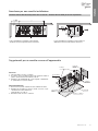
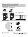
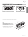
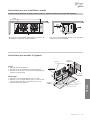
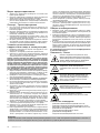
Avvertenze per una corretta installazione
Distanza minima laterale dalla parete lato resistenze e distanza minima dalla parete lato aspirazione
In fase di installazione rispettare la quota minima
A+250 mm per poter togliere/inserire le resistenze.
In fase di installazione rispettare la quota minima di
800 mm per un buon funzionamento del motore.
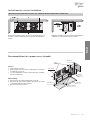
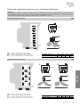
Accesso
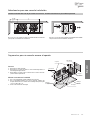
1. Smontare il tubo di scarico condensa.
2. Accertarsi che la vaschetta sia libera da eventuali residui di
ghiaccio prima di rimuoverla svitando le viti “A”.
3. Allentare le viti autofilettanti “B”, senza toglierle completamen-
te, quindi sfilare il coperchio laterale.
Riposizionamento
1. Ricollocare il coperchio laterale e fissarlo mediante le viti “B”.
2. Rimettere la vaschetta in posizione, avendo cura che i coper-
chi laterali siano interni alla stessa,
quindi fissarla con le viti “A”.
3. Rimontare il tubo di scarico condensa.
Sostegni
Coperchio
laterale
Scatola di
derivazione
Vaschetta
Scarico condensa
Sgocciolatoio
interno
Convogliatore
Suggerimenti per un corretto accesso all’apparecchio

4
www.modine.com
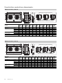
Modello con ventola ø 630 mm
198 198
822
B
DC
A
1130
15
80
80
25x20
45
732
63
574
637
240
877
F
4RR
RBB1
RBB2
RBB3
RBA1
RBA2
RBA3
RSA1
RSB1
RSA1
6RR
RSB1
RBB1
RBB3
RBA2
RBA4
RBA5
RBA6
RBB2
RBA1
RBA3
RBA1
RBB1
RBA5
RBA3
RBA6
RBA7
RBA10
RBA9
RSA1
RSB1
8RR
RBA4
RBA2
RBA8
F
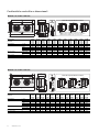
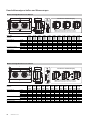
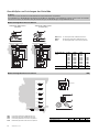
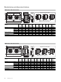
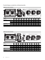
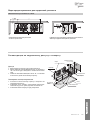
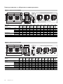
Modello CDC 631E4 631A4 631B4 632E4 632A4 632B4 633E4 633A4 633B4 634E4 634A4 634B4
ø 630 mm 631E6 631A6 631B6 632E6 632A6 632B6 633E6 633A6 633B6 634E6 634A6 634B6
631E8 631A8 631B8 632E8 632A8 632B8 633E8 633A8 633B8 634E8 634A8 634B8
Motoventilatori n° x Ø 1x630 1x630 1x630 2x630 2x630 2x630 3x630 3x630 3x630 4x630 4x630 4x630
Dimensioni A mm 1606 1606 1606 2706 2706 2706 3806 3806 3806 4906 4906 4906
B mm 1174 1174 1174 2274 2274 2274 3374 3374 3374 4474 4474 4474
C mm ---------2237 2237 2237
D mm ---------2237 2237 2237
Attacchi batteria In tube (mm) 12 - 16 16 16 16 16 - 22 22 22 22 22 22 22 - 28 28
Out tube (mm) 16 - 22 22 22 22 - 28 28 28 28 28 28 28 35 35
Attacco scarico
GAS 222222222222
Peso netto (max) kg 120 150 180 210 260 320 340 440 540 450 590 720
Particolari di posizionamento resistenze
RBA - Resistenza elettrica di alta potenza nella batteria.
RBB - Resistenza elettrica di bassa potenza nella batteria.
RSA - Resistenza elettrica sullo sgocciolatoio interno.
Caratteristiche costruttive e dimensionali
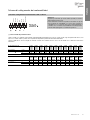
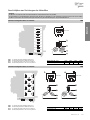
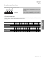
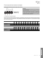
Modello con ventola ø 500 mm
F
35
35
40
12
72
4RR
RSA1
RBA3
RBA4
RBA2
RBA1
RBB2
RBB1
6RR
RSA1
RBA3
RBA4
RBA2
RBA1
RBB2
RBB1
8RR
RSA1
RBA3
RBA4
RBA2
RBA1
RBB2
RBB1
A
B
C D
140
= =
660
100
74
770
55
456
511
197
708
550
61
671
Modello CDC 501E4 501A4 501B4 502E4 502A4 502B4 503E4 503A4 503B4 504A4 504B4
ø 500 mm 501E6 501A6 501B6 502E6 502A6 502B6 503E6 503A6 503B6 504A6 504B6
501E8 501A8 501B8 502E8 502A8 502B8 503E8 503A8 503B8 504A8 504B8
Motoventilatori n° x Ø 1x500 1x500 1x500 2x500 2x500 2x500 3x500 3x500 3x500 4x500 4x500
Dimensioni A mm 1184 1184 1184 2034 2034 2034 2884 2884 2884 3734 3734
B mm 880 880 880 1730 1730 1730 2580 2580 2580 3430 3430
C mm ---------1730 1730
D mm ---------1700 1700
Attacchi batteria In tube (mm) 12 12 12 12 - 16 16 16 16 16 16 22 22
Out tube (mm) 16 16 - 22 16 - 22 16 - 22 22 22 22 22 - 28 28 28 28
Attacco scarico
GAS 22222222222
Peso netto (max) kg 73,2 84,0 97,2 127,2 150,0 174,0 181,2 216,0 250,8 283,2 328,8
Particolari di posizionamento resistenze
Particolare
di fissaggio
RBA - Resistenza elettrica di alta potenza nella batteria.
RBB - Resistenza elettrica di bassa potenza nella batteria.
RSA - Resistenza elettrica sullo sgocciolatoio interno.

5
www.modine.com
Italiano
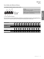
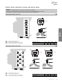
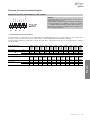
Schema di collegamento motoventilatori ø 500 - 630 mm
( * ) Termocontatti di protezione interni
I termocontatti sono elementi di azionamento dipendenti dalla temperatura che vengono inseriti, isolati, negli avvolgimenti dei motori; essi
aprono un contatto elettrico quando viene superata la temperatura permanente massima ammissibile.
I termocontatti devono essere collegati ai circuiti di comando dei contattori di modo che in caso di disturbi non si abbia una reinserzione
automatica.
Attenzione
Seguire rigorosamente gli schemi elettrici riportati per evitare il
danneggiamento del motore.
Prima di utilizzare sistemi di regolazione del numero di giri dei
motori verificare la compatibilità con i motori stessi, sistemi non
compatibili possono generare rumorosità e danneggiamenti; il
costruttore non si assume responsabilità alcuna sulle prestazio-
ni dei modelli equipaggiati con sistemi di regolazione.
Alta velocità
collegamento
q
400V/3/50Hz
Arancio
Marrone
Rosso
Blu
Grigio
Nero
Giallo/vede
Modello CDC Ø 500 mm 501E4 501A4 501B4 502E4 502A4 502B4 503E4 503A4 503B4 504A4 504B4
501E6 501A6 501B6 502E6 502A6 502B6 503E6 503A6 503B6 504A6 504B6
501E8 501A8 501B8 502E8 502A8 502B8 503E8 503A8 503B8 504A8 504B8
Motoventilatori n° x Ø 1x500 1x500 1x500 2x500 2x500 2x500 3x500 3x500 3x500 4x500 4x500
Assorbimento (
q
)A 1,7 1,7 1,7 3,4 3,4 3,4 5,1 5,1 5,1 6,8 6,8
W 770 770 770 1540 1540 1540 2310 2310 2310 3080 3080
Modello CDC Ø 630 mm 631E4 631A4 631B4 632E4 632A4 632B4 633E4 633A4 633B4 634E4 634A4 634B4
631E6 631A6 631B6 632E6 632A6 632B6 633E6 633A6 633B6 634E6 634A6 634B6
631E8 631A8 631B8 632E8 632A8 632B8 633E8 633A8 633B8 634E8 634A8 634B8
Motoventilatori n° x Ø 1x630 1x630 1x630 2x630 2x630 2x630 3x630 3x630 3x630 4x630 4x630 4x630
Assorbimento (
q
)A 3,7 3,7 3,7 7,4 7,4 7,4 11,1 11,1 11,1 14,8 14,8 14,8
W 1750 1750 1750 3500 3500 3500 5250 5250 5250 7000 7000 7000
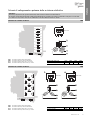
Schema di collegamento dei motoventilatori

6
www.modine.com
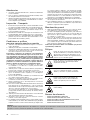
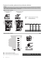
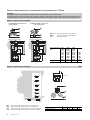
Schemi di collegamento e potenze delle resistenze elettriche
Attenzione
È d’obbligo l’applicazione di opportuni sistemi di protezione termica sulle linee di alimentazione.
Provvedere periodicamente alla verifica delle funzionalità di tutte le resistenze per evitare accumuli dannosi di ghiaccio sui modelli.
Il costruttore non risponde in alcun modo di difettosità create da malfunzionamenti non rilevati.
W1
V2U2W2
V1U1
RSA1
RSB1
V1
V2
W2
W1
400V/3/50Hz
R
S
T
N
U1
U2
W2
W1
V2
V1
RSA1
RSB1
RBB3
RBA1
RBB2
RBB1
RBA2
RBA3
U2
U1
RBB1
RBB2
RBB3
RBA1
RBA2
RBA3
U1
U2
W1
W2
U1
U2
V1
V2
V1
V2
RBA Resistenze di alta potenza nella batteria
RBB Resistenze di bassa potenza nella batteria
RSA Resistenze di alta potenza sullo sgocciolatoio
RSB Resistenze di bassa potenza sullo sgocciolatoio
Modello con ventola ø 630 mm 4RR
Modello CDC "ED" ø 630 631E 632E 633E 634E
Potenza totale (W) 5400 11760 17760 23400
COLLEGAMENTO 400V/3/50 Hz COLLEGAMENTO 230V/3/50 Hz
(predisposto) (da predisporre)
RBA1-2-3-4 Resistenze di alta potenza nella batteria.
RBB1-2 Resistenza di bassa potenza nella batteria.
RSA1 Resistenza di alta potenza sullo sgocciolatoio interno.
Modello con ventola ø 500 mm
Modello CDC “ED” 501E4 502E4 503E4 -
ø 500 501E6 502E6 503E6 -
501E8 502E8 503E8 -
501A4 502A4 502A4 504A4
501A6 502A6 502A6 504A6
501A8 502A8 502A8 504A8
501B4 502B4 502B4 504B4
501B6 502B6 502B6 504B6
501B8 502B8 502B8 504B8
Potenza totale (W) 5040 10200 15000 19800

7
www.modine.com
Italiano
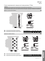
Schemi di collegamento e potenze delle resistenze elettriche
Attenzione
È d’obbligo l’applicazione di opportuni sistemi di protezione termica sulle linee di alimentazione.
Provvedere periodicamente alla verifica delle funzionalità di tutte le resistenze per evitare accumuli dannosi di ghiaccio sui modelli.
Il costruttore non risponde in alcun modo di difettosità create da malfunzionamenti non rilevati.
Modello CDC “ED” ø 630 631B 632B 633B 634B
Potenza totale (W) 10800 23520 35520 46800
Modello CDC “ED” ø 630 631A 632A 633A 634A
Potenza totale (W) 8100 17640 26640 35100
W1
V2U2W2
V1U1
RSA1
RSB1
V1
V2
W2
W1
400V/3/50Hz
R
S
T
N
U1
U2
W2
W1
V2
V1
RBA2
RBA1
RBA3
RBA4
RBA6
RBA5
R
S
T
N
U1
U2
W2
W1
V2
V1
RBA8
RBA7
RBA9
RBA10
RSB1
RSA1
RBB1
1
W1
V2U2W2
V1U1
400V/3/50Hz
2
U2
U1
RBA1
RBA4
V1
V2
U2
U1
RBA2
W2
W1
RBB1
W2
W1
RBA5
V1
V1
RBA3
W2
W1
RBA6
U2
U1
RBA7
U1
RBA8
U2
V2
V1
RBA10
V2
V1
RBA9
1 2
1
1
1
1
1
2
2
2 2
2
2
RBA Resistenze di alta potenza nella batteria
RBB Resistenze di bassa potenza nella batteria
RSA Resistenze di alta potenza sullo sgocciolatoio
RSB Resistenze di bassa potenza sullo sgocciolatoio
Modello con ventola ø 630 mm 8RR
W1
V2
R
S
T
N
U1
U2
W2
W1
V2
V1
U2W2
V1U1
RSA1
RSA6
RBA5
U2
U1
RBB1
RBB3
RBA2
RBA4
RBA5
RBA6
RSA1
RSB1
V1
V2
U1
U2
V1
V2
W1
W2
W1
W2
V1
V2
W2
W1
RBA1
RBB2
RBB1
RSB1
RBA3
U2
U1
RBB2
RBA1
U1
U2
RBA3
V1
V2
RBA2
RBB3
RBA4
400V/3/50Hz
RBA Resistenze di alta potenza nella batteria
RBB Resistenze di bassa potenza nella batteria
RSA Resistenze di alta potenza sullo sgocciolatoio
RSB Resistenze di bassa potenza sullo sgocciolatoio
Modello con ventola ø 630 mm 6RR

8
www.modine.com
Achtung
Versichern Sie sich vor jeder Wartung, daß die Stromzuführung vom Hauptnetz getrennt ist; die elektrischen Teile könnten automatisch
anlaufen.
Hinweise
1. Diese Betriebsanleitung während der ganzen Lebensdauer des
Geräts aufbewahren.
2. Vor Inbetriebnahme des Geräts und vor jedem Eingriff auf-
merksam die Betriebsanleitung durchlesen.
3. Das Gerät nur für den Zweck einsetzen, wofür es entworfen
worden ist; unsachgemäße Anwendung befreit den Hersteller
von jeder Verantwortung.
Kontrolle - Transport
1. Bei Erhalt des Geräts sofort den Zustand kontrollieren; jegli-
chen eventuellen Schaden sofort dem Spediteur beanstanden.
2. Während des Transports unnötigen Druck auf die Verpackung
vermeiden.
3. Während der Montage und des Positionierens des Geräts geei-
gnete Schutzhandschuhe benutzen, um eine Verletzungsgefahr
durch scharfe Stellen am Gerät zu vermeiden.
4. Während der Montage und des Positionierens des Geräts
geeignete Schutzhandschuhe benutzen, um eine
Verletzungsgefahr durch scharfe Stellen (z.B. Lamellen) zu
vermeiden.
Hinweise für eine korrekte
Inbetriebnahme
1. Die Tragfähigkeit der Strukturen bezüglich des Gerätegewichts
überprüfen.
2. Das Modell muß horizontal eingebaut werden.
3. Für eine einwandfreie Luftzirkulation muß genügend Freiraum
vorhanden sein (ungefähr 30% des Innenvolumens der Zelle).
Besondere Einbau- oder Betriebsbedingungen, wie niedrige
Kühlzellen, Deckenträger, übermäßige Lagerung,
Behinderungen des Luftstroms und/oder der Luftansaugung,
übermäßige Reifbildung durch zu hohe Feuchtigkeit in der
Kühlzelle können die angegebenen Leistungen negativ beein-
flussen und Schäden an den Geräten hervorrufen.
Die Standardmodelle können für die Anwendung in
Schnellabkühlungs- oder Schockräumen nicht geeignet sein.
4. Die Modelle sind mit Axialmotorventilatoren ausgestattet und
daher nicht kanalisierbar oder jedenfalls keine weiteren
Druckverluste verkraften.
5. Die Betriebsbedingungen (Temperaturen und Drucke) müssen
dem Projekt entsprechen.
6. Das Anschließen muß sorgfältig erfolgen, um das Verformen
eventueller Kapillarrohre und das Verlagern des Verteilers zu
verhindern.
7. Bei nah aneinander installierten Geräten abwechselnde
Abtauungen vermeiden.
8. An den Tauwasserabflüssen die passenden Siphone installie-
ren und die Wirksamkeit bei allen Anwendungstemperaturen
überprüfen.
9. Die Installation der Luftverdampfer in der Nähe der Zellentüren
vermeiden.
10. Die Temperaturfühler für das Ende der Abtauung in den kälte-
sten Zonen der Wärmeaustauscher anbringen, beziehungswei-
se in den Zonen, wo die Tendenz zur Eisbildung am größten ist
(am Ende der Abtauung darf kein Eis an den Modellen blei-
ben). Die Lage dieser kann nicht vorherbestimmt werden, da
sie sich je nach Typ der Zelle und der Anlage verändert.
11. Die Stromzuleitung muß den elektrischen Daten des Geräts
angepaßt sein.
12. Alle Anschlüsse müssen den gültigen elektrischen Normen ent-
sprechen.
13. Die Einheiten sind für den elektrischen Erdungsanschluss vor-
gesehen. Der Installationsfachmann bzw. Betreiber der Einheit
muss einen funktionstüchtigen Anschluss an den
Erdungsschutzleiter gegen indirekte Stromkontakte gewährlei-
sten. Die elektrischen Widerstände für das Abtausystem sind in
einer Verteilerdose aus thermoplastischem Material unterge-
bracht mit Schutzgrad IP 54. Auf Bestellung können die
Modelle mit nicht standardmäßigen Wärmetauschern,
Abtausystemen und Lüfteraggregaten geliefert werden.
14. Nach beendeter Installation den am Gerät befindlichen
Schutzfilm entfernen.
15. Der Zugang zum Gerät für jeden Eingriff muß dem für die
Anlage qualifizierten Personal gemäß den gültigen Normen
vorbehalten sein.
Allgemeine Wartung
1. Regelmäßige Überprüfung der Befestigungen der elektrischen
Anschlüsse. Kältemittelanschlüsse auf Dichtheit prüfen.
2. Regelmäßige Reinigung des Geräts mit normalem
Seifenwasser, um das Anhäufen von schädlichen Substanzen
zu verhindern. Keine Lösungsmittel und aggressive oder
ammoniakhaltige Reibepulver verwenden.
3. Beim eventuellen Auswechseln von elektrischen Heizstäben
besonders achtgeben, um während der Installation Schäden an
der Vulkanisierung zu vermeiden; die Anschlüsse und die
bestehenden Befestigungssysteme wieder korrekt herstellen,
um zu vermeiden, daß sie sich während des Betriebs bewegen.
Die Wartung darf nur von qualifizierten Personal vorgenom-
men werden.
Gefahren
1. Stromschlaggefahr. Das Gerät ist mit
Motorventilatoren und elektrischen
Abtauheizungen versehen. Die Stromspannung
ist 400 V AC. Elektrische Sicherheitssysteme
gemäß den geltenden Normen anwenden.
2. Verbrennungsgefahr. Die elektrischen
Abtauheizungen können
Oberflächentemperaturen von 350° C erreichen.
3. Schnittgefahr. Der Wärmeaustauscher besteht
aus Lamellen mit scharfen Kanten und das
Gehäuse besteht aus Blechteilen.
4. Gefahr durch sich bewegende Teile. Das Gerät ist
mit Motorventilatoren mit äußerem Schutzgitter
versehen.
5. Quetschgefahr. Das Gerät kann über 500 kg
wiegen.
Bezugsnormen
- MASCHINEN - RICHTLINIE 2006/42/EC
- NIEDERSPANNUNG - RICHTLINIE 2014/35/UE
- RICHTLINIE ELEKTROMAGNETISCHE KOMP. 2014/30/UE
- PED RICHTLINIE 2014/68/UE
- ERP RICHTLINIE 2009/125/EC

9
www.modine.com
Deutsch
Ausbau
1. Tauwasserabflußrohr demontieren.
2. Befestigungsschrauben “A” der Tropfwanne von der inneren
Tropfwanne losschrauben.
3. Die selbstbohrenden Schrauben “B” lockern, ohne sie jedoch
ganz abzuschrauben und die seitliche Abdeckung abnehmen.
Zusammenbau
1. Die seitliche Abdeckung mit den Schrauben “B” befestigen.
2. Tropfwanne so positionieren, daß die seitlichen Abdeckungen
innen sind und mit den Schrauben “A” befestigen.
3. Tauwasserabflußrohr montieren.
Ratschläge für einen korrekten Zugang zum Gerät
Halterungen
Seitliche
Abdeckung
Abzweigdose
Tropfwanne
Tauwasserabfluß
Innere
Tropfwanne
Lüfterblech
Hinweise für eine korrekte Aufstellung
Mindestabstand von der Wand, Heizstabseite - Mindestabstand von der Wand, Ansaugseite
Zum seitlichen Ein- und Ausbau der Heizstäbe muß bei der
Geräteinstallation das Mindestmaß A+250 mm eingehalten wer-
den.
Für einen optimalen Betrieb des Motors den
Mindestabstand 800 mm bei der Montage einhalten.

10
www.modine.com
Modell mit Flügeldurchmesser 630 mm
198 198
822
B
DC
A
1130
15
80
80
25x20
45
732
63
574
637
240
877
F
4RR
RBB1
RBB2
RBB3
RBA1
RBA2
RBA3
RSA1
RSB1
RSA1
6RR
RSB1
RBB1
RBB3
RBA2
RBA4
RBA5
RBA6
RBB2
RBA1
RBA3
RBA1
RBB1
RBA5
RBA3
RBA6
RBA7
RBA10
RBA9
RSA1
RSB1
8RR
RBA4
RBA2
RBA8
F
Modell CDC 631E4 631A4 631B4 632E4 632A4 632B4 633E4 633A4 633B4 634E4 634A4 634B4
ø 630 mm 631E6 631A6 631B6 632E6 632A6 632B6 633E6 633A6 633B6 634E6 634A6 634B6
631E8 631A8 631B8 632E8 632A8 632B8 633E8 633A8 633B8 634E8 634A8 634B8
Motorventilatoren n° x Ø 1x630 1x630 1x630 2x630 2x630 2x630 3x630 3x630 3x630 4x630 4x630 4x630
Abmessungen A mm 1606 1606 1606 2706 2706 2706 3806 3806 3806 4906 4906 4906
B mm 1174 1174 1174 2274 2274 2274 3374 3374 3374 4474 4474 4474
C mm ---------2237 2237 2237
D mm ---------2237 2237 2237
Inn. Batterieanschlüsse In tube (mm) 12 - 16 16 16 16 16 - 22 22 22 22 22 22 22 - 28 28
Out tube (mm) 16 - 22 22 22 22 - 28 28 28 28 28 28 28 35 35
Tauwasserabfluß
GAS 222222222222
Nettogewicht (max) kg 120 150 180 210 260 320 340 440 540 450 590 720
Einzelheit der Heizstäbebefestigung
RBA - Hochleistungsheizstab im Wärmeaustauscher.
RBB - Niederleistungsheizstab im Wärmeaustauscher.
RSA - Elektrischer Heizstab in der inneren Tropfwanne.
Konstruktionseigenschaften und Abmessungen
Modell mit Flügeldurchmesser 500 mm
F
35
35
40
12
72
4RR
RSA1
RBA3
RBA4
RBA2
RBA1
RBB2
RBB1
6RR
RSA1
RBA3
RBA4
RBA2
RBA1
RBB2
RBB1
8RR
RSA1
RBA3
RBA4
RBA2
RBA1
RBB2
RBB1
A
B
C D
140
= =
660
100
74
770
55
456
511
197
708
550
61
671
Modell CDC 501E4 501A4 501B4 502E4 502A4 502B4 503E4 503A4 503B4 504A4 504B4
ø 500 mm 501E6 501A6 501B6 502E6 502A6 502B6 503E6 503A6 503B6 504A6 504B6
501E8 501A8 501B8 502E8 502A8 502B8 503E8 503A8 503B8 504A8 504B8
Motorventilatoren n° x Ø 1x500 1x500 1x500 2x500 2x500 2x500 3x500 3x500 3x500 4x500 4x500
Abmessungen A mm 1184 1184 1184 2034 2034 2034 2884 2884 2884 3734 3734
B mm 880 880 880 1730 1730 1730 2580 2580 2580 3430 3430
C mm ---------1730 1730
D mm ---------1700 1700
Innere Batterieanschlüsse In tube (mm) 12 12 12 12 - 16 16 16 16 16 16 22 22
Out tube (mm) 16 16 - 22 16 - 22 16 - 22 22 22 22 22 - 28 28 28 28
Tauwasserabfluß
GAS 22222222222
Nettogewicht (max) kg 73,2 84,0 97,2 127,2 150,0 174,0 181,2 216,0 250,8 283,2 328,8
Einzelheit der Heizstäbebefestigung
Einzelheit
der
Befestigung
RBA - Hochleistungsheizstab im Wärmeaustauscher.
RBB - Niederleistungsheizstab im Wärmeaustauscher.
RSA - Elektrischer Heizstab in der inneren Tropfwanne.

11
www.modine.com
Deutsch
Modello CDC Ø 630 mm 631E4 631A4 631B4 632E4 632A4 632B4 633E4 633A4 633B4 634E4 634A4 634B4
631E6 631A6 631B6 632E6 632A6 632B6 633E6 633A6 633B6 634E6 634A6 634B6
631E8 631A8 631B8 632E8 632A8 632B8 633E8 633A8 633B8 634E8 634A8 634B8
Motorventilatoren n° x Ø 1x630 1x630 1x630 2x630 2x630 2x630 3x630 3x630 3x630 4x630 4x630 4x630
Stromaufnahme (
q
)A 3,7 3,7 3,7 7,4 7,4 7,4 11,1 11,1 11,1 14,8 14,8 14,8
W 1750 1750 1750 3500 3500 3500 5250 5250 5250 7000 7000 7000
Anschlußplan der Motorventilatoren ø 500 - 630 mm
( * ) Innere Schutztemperaturwächter
Die Temperaturwächter sind temperaturunabhängige Schaltelemente, die in die Wicklungen der Motoren isoliert eingebettet werden; sie
öffnen einen elektrischen Kontakt, sobald die höchstzulässige Dauertemperatur überschritten wird.Die Temperaturwächter sind so in den
Steuerstromkreis von Schützen einzufügen, daß im Störungsfalle keine selbsttätige Wiedereinschaltung erfolgt.
Achtung
Um Schäden am Motor zu vermeiden, ist genau nach dem auf-
geführten Anschlußplan vorzugehen.
Vor Anwendung von Drehzahlreglern die Eignung für die Motoren
überprüfen, nicht verträgliche Systeme können Lärm und Schäden
am Motor hervorrufen; der Hersteller lehnt jede Verantwortung für
mit Drehzahlreglern ausgestattete Geräte ab.
Hohe
Geschwindigkeit
Anschluß
q
400V/3/50Hz
Orange
Braun
Rot
Hellblau
Grau
Schwarz
Gelb/grün
Modell CDC Ø 500 mm 501E4 501A4 501B4 502E4 502A4 502B4 503E4 503A4 503B4 504A4 504B4
501E6 501A6 501B6 502E6 502A6 502B6 503E6 503A6 503B6 504A6 504B6
501E8 501A8 501B8 502E8 502A8 502B8 503E8 503A8 503B8 504A8 504B8
Motorventilatoren n° x Ø 1x500 1x500 1x500 2x500 2x500 2x500 3x500 3x500 3x500 4x500 4x500
Stromaufnahme (
q
)A 1,7 1,7 1,7 3,4 3,4 3,4 5,1 5,1 5,1 6,8 6,8
W 770 770 770 1540 1540 1540 2310 2310 2310 3080 3080
Anschlußplan der Motorventilatoren

12
www.modine.com
W1
V2U2W2
V1U1
RSA1
RSB1
V1
V2
W2
W1
400V/3/50Hz
R
S
T
N
U1
U2
W2
W1
V2
V1
RSA1
RSB1
RBB3
RBA1
RBB2
RBB1
RBA2
RBA3
U2
U1
RBB1
RBB2
RBB3
RBA1
RBA2
RBA3
U1
U2
W1
W2
U1
U2
V1
V2
V1
V2
RBA Hochleistungsheizstab im Wärmeaustauscher.
RBB Niederleistungsheizstab im Wärmeaustauscher.
RSA Hochleistungsheizstab in der inneren Tropfwanne.
RSB Niederleistungsheizstab in der inneren Tropfwanne.
Modell mit Flügeldurchmesser 630 mm 4RR
Modell CDC “ED” ø 630 631E 632E 633E 634E
Gesamtleistung (W) 5400 11760 17760 23400
ANSCHLUß 400V/3/50 Hz ANSCHLUß 230V/3/50 Hz
(standard) (vorzubereiten)
RBA1-2-3-4 Hochleistungsheizstab im Wärmeaustauscher.
RBB1-2 Niederleistungsheizstab im Wärmeaustauscher.
RSA1 Hochleistungsheizstab in der inneren Tropfwanne.
Anschlußplan und Leistungen der Heizstäbe
Modell mit Flügeldurchmesser 500 mm
Achtung
die Motoren sind mit automatisch wiederaufrüstbaren Temperaturwächtern ausgestattet.
Vor Anwendung von Drehzahlreglern die Eignung für die Motoren überprüfen; nicht verträgliche Systeme können Lärm und Schäden
am Motor hervorrufen; der Hersteller lehnt jede Verantwortung für mit Drehzahlreglern ausgestattete Geräte ab.
Modell CDC “ED” 501E4 502E4 503E4 -
ø 500 501E6 502E6 503E6 -
501E8 502E8 503E8 -
501A4 502A4 502A4 504A4
501A6 502A6 502A6 504A6
501A8 502A8 502A8 504A8
501B4 502B4 502B4 504B4
501B6 502B6 502B6 504B6
501B8 502B8 502B8 504B8
Gesamtleistung (W) 5040 10200 15000 19800

13
www.modine.com
Anschlußplan und Leistungen der Heizstäbe
Achtung
die Motoren sind mit automatisch wiederaufrüstbaren Temperaturwächtern ausgestattet.
Vor Anwendung von Drehzahlreglern die Eignung für die Motoren überprüfen; nicht verträgliche Systeme können Lärm und Schäden
am Motor hervorrufen; der Hersteller lehnt jede Verantwortung für mit Drehzahlreglern ausgestattete Geräte ab.
Modell CDC “ED” ø 630 631B 632B 633B 634B
Gesamtleistung (W) 10800 23520 35520 46800
Modell CDC “ED” ø 630 631A 632A 633A 634A
Gesamtleistung (W) 8100 17640 26640 35100
W1
V2U2W2
V1U1
RSA1
RSB1
V1
V2
W2
W1
400V/3/50Hz
R
S
T
N
U1
U2
W2
W1
V2
V1
RBA2
RBA1
RBA3
RBA4
RBA6
RBA5
R
S
T
N
U1
U2
W2
W1
V2
V1
RBA8
RBA7
RBA9
RBA10
RSB1
RSA1
RBB1
1
W1
V2U2W2
V1U1
400V/3/50Hz
2
U2
U1
RBA1
RBA4
V1
V2
U2
U1
RBA2
W2
W1
RBB1
W2
W1
RBA5
V1
V1
RBA3
W2
W1
RBA6
U2
U1
RBA7
U1
RBA8
U2
V2
V1
RBA10
V2
V1
RBA9
1 2
1
1
1
1
1
2
2
2 2
2
2
RBA Hochleistungsheizstab im Wärmeaustauscher.
RBB Niederleistungsheizstab im Wärmeaustauscher.
RSA Hochleistungsheizstab in der inneren Tropfwanne.
RSB Niederleistungsheizstab in der inneren Tropfwanne.
Modell mit Flügeldurchmesser 630 mm 8RR
W1
V2
R
S
T
N
U1
U2
W2
W1
V2
V1
U2W2
V1U1
RSA1
RSA6
RBA5
U2
U1
RBB1
RBB3
RBA2
RBA4
RBA5
RBA6
RSA1
RSB1
V1
V2
U1
U2
V1
V2
W1
W2
W1
W2
V1
V2
W2
W1
RBA1
RBB2
RBB1
RSB1
RBA3
U2
U1
RBB2
RBA1
U1
U2
RBA3
V1
V2
RBA2
RBB3
RBA4
400V/3/50Hz
RBA Hochleistungsheizstab im Wärmeaustauscher.
RBB Niederleistungsheizstab im Wärmeaustauscher.
RSA Hochleistungsheizstab in der inneren Tropfwanne.
RSB Niederleistungsheizstab in der inneren Tropfwanne.
Modell mit Flügeldurchmesser 630 mm 6RR
Deutsch

14
www.modine.com
Caution
Before carrying out maintenance on unit, make sure that the electric feed is disconnecdcd from main power source: the electric parts
may be connecdcd to an automatic control system.
Important
1. Keep this manual for the lifespan of model.
2. Read technical manual carefully before installation and prior to
any intervention on model.
3. Use model exclusively for the purpose for which it has been
designed; misuse exempts manufacturer from any responsibility.
Inspection - Transport
1. Upon delivery immediately examine condition of model; should
damages be detecdcd promptly notify forwarder.
2. During transport of model it is necessary to avoid pressure on
packaging and it must be kept in upright position as indicated
on package.
3. Unpack model as close as possible to installation site. When
packaging is removed from model, care must be exercised in
order to avoid damage to parts.
4. In order to avoid injury from the model's sharp edges (e.g. fins)
during installation and positioning of model use of special pro-
tective gloves is recommended.
For a proper installation
1. Verify structural bearing of ceiling in relation to the weight of
the unit.
2. Verify that the unit is installed horizontally.
3. Ensure an adequate free space (approx. 30% of the inner
room volume) to allow a proper intake and exhaust air circu-
lation.
Particular conditions of installation or operation such as low
or beamed rooms, overstorage, obstrucdcd intake and exhau-
st air circulation and improper ice build-up due to excessive
entry of humidity in room may negatively affect the stated
performance and may cause defects.
Standard models may not be suitable for blast freezer and
chill room application.
4. The models are equipped with axial fan motors, therefore not
suitable for duct ventilation systems and cannot sustain extra
static air pressure drops.
5. Verify that the operating conditions (temperatures and pressu-
res) are in accordance to those of project.
6. Care must be exercised during the connecting phase in order
to avoid possible distortion of the capillary tubes and shifting of
the distributor.
7. In the case of more than one model installed at close range it is
advisable to avoid alternate defrostings.
8. Fit the appropriate siphons on the condensate drain connec-
tions and assess their efficiency in all working temperatures.
9. Avoid installation of the units next to the cold-room doors.
10. Place the end of defrost temperature feeler in the coldest areas
of the coil, i.e. the areas that tend to freeze more (at the end of
the cycle the unit should be completely ice-free).
The position of this device cannot be defined in advance,
because it varies in accordance to the type cold room and type
of installation.
11. Verify that the electrical feed network is in accordance to the
electrical features of model.
12. Ensure that all the electric wiring is in compliance with the stan-
dards in force.
13. The units are predisposed for ground wiring connection.
The unit installer and/or plant operator must ensure the presen-
ce of an efficient earthing connection to protect against indirect
electric contacts.
The electric heating elements eventually used for defrosting
are housed in junction boxes made of thermoplastic material,
with protection rating IP 54.
Upon request, models can be supplied with coils, defrosting
units and fan motors different from the standard ones.
14. The protective film is to be removed from model upon comple-
tion of installation.
15. Access to model, for any type of intervention, is reserved to
qualified personnel as per regulations in force.
General Maintenance
1. Periodically inspect fastenings, electrical connections and con-
nections to cooling installation.
2. It is necessary to arrange periodical cleaning of unit in order to
avoid deposits of toxic substances. Use of mild detergent is
recommended; avoid use of solvents, aggressive, abrasive or
ammonia-based agents.
3. When replacing electric heaters take particular care during
installation in order to avoid damage to the vulcanization; cor-
rectly reset wiring and existing fastening systems to avoid pos-
sible movement during operation.
The above-mentioned operations are to be carried out by qua-
lified personnel only.
Hazards / Risks
1. Electric shock. The model is equipped with fan
motors and electric defrost heaters. The supply
voltage is 400 V AC. It is important to use
electrical safety systems that are in compliance to
the regulations in force.
2. Burns. The surface of the electric defrost heaters
can reach the temperature of 350 °C.
3. Cuts. The heat exchanger is made with fins with
sharp edges and the casing is made of sheet
metal parts.
4. Parts in motion. The model is equipped with fan
motors fitted with external protection.
5. Crushing. The weight of unit may exceed 500 kg.
Reference standards
- MACHINES DIRECTIVE 2006/42/EC
- LOW-VOLTAGE DIRECTIVE 2014/35/UE
- ELECTROMAGNETIC COMPATIBILITY DIR. 2014/30/UE
- PED DIRECTIVE 2014/68/UE
- ERP DIRECTIVE 2009/125/EC

15
www.modine.com
English
Instructions for a correct installation
Minimum distance from wall on heater side - Minimum distance from wall on suction side
During the installation phase observe the minimum dimension
A+250 as to allow an adequate space for the removal and fitting of
heaters.
During the installation phase observe the minimun distance
of 800 mm as to allow proper functioning of motor.
Access
1. Remove drain connection.
2. Verify that drip tray is free from ice build-up before removing it
by unfastening screws “A”.
3. Loosen self-threading screws “B”, without removing completely,
then slip off side panel.
Remounting
1. Reposition the side panel and fasten with screws “B”.
2. Reposition drip tray, ensuring that the side panels are placed
on the inside and fasten with screws “A”.
3. Reconnect the drain connection.
Recommendations for a proper access to model
Support
brackets
Side panel
Terminal
box
Drip tray
Drain connection
Inner drip tray
Fan shroud

16
www.modine.com
Model with ø 630 mm fan motor
198 198
822
B
DC
A
1130
15
80
80
25x20
45
732
63
574
637
240
877
F
4RR
RBB1
RBB2
RBB3
RBA1
RBA2
RBA3
RSA1
RSB1
RSA1
6RR
RSB1
RBB1
RBB3
RBA2
RBA4
RBA5
RBA6
RBB2
RBA1
RBA3
RBA1
RBB1
RBA5
RBA3
RBA6
RBA7
RBA10
RBA9
RSA1
RSB1
8RR
RBA4
RBA2
RBA8
F
Model CDC 631E4 631A4 631B4 632E4 632A4 632B4 633E4 633A4 633B4 634E4 634A4 634B4
ø 630 mm 631E6 631A6 631B6 632E6 632A6 632B6 633E6 633A6 633B6 634E6 634A6 634B6
631E8 631A8 631B8 632E8 632A8 632B8 633E8 633A8 633B8 634E8 634A8 634B8
Fan motors n° x Ø 1x630 1x630 1x630 2x630 2x630 2x630 3x630 3x630 3x630 4x630 4x630 4x630
Dimensions A mm 1606 1606 1606 2706 2706 2706 3806 3806 3806 4906 4906 4906
B mm 1174 1174 1174 2274 2274 2274 3374 3374 3374 4474 4474 4474
C mm ---------2237 2237 2237
D mm ---------2237 2237 2237
Coil inner connections In tube (mm) 12 - 16 16 16 16 16 - 22 22 22 22 22 22 22 - 28 28
Out tube (mm) 16 - 22 22 22 22 - 28 28 28 28 28 28 28 35 35
Drain connections
GAS 222222222222
Net weight (max) kg 120 150 180 210 260 320 340 440 540 450 590 720
Positioning of electric heaters
RBA - High power electric heater in coil.
RBB - Low power electric heater in coil.
RSA - Electric heater on inner drip tray.
Manufacturing and dimensional features
Model with ø 500 mm fan motor
F
35
35
40
12
72
4RR
RSA1
RBA3
RBA4
RBA2
RBA1
RBB2
RBB1
6RR
RSA1
RBA3
RBA4
RBA2
RBA1
RBB2
RBB1
8RR
RSA1
RBA3
RBA4
RBA2
RBA1
RBB2
RBB1
A
B
C D
140
= =
660
100
74
770
55
456
511
197
708
550
61
671
Model CDC 501E4 501A4 501B4 502E4 502A4 502B4 503E4 503A4 503B4 504A4 504B4
ø 500 mm 501E6 501A6 501B6 502E6 502A6 502B6 503E6 503A6 503B6 504A6 504B6
501E8 501A8 501B8 502E8 502A8 502B8 503E8 503A8 503B8 504A8 504B8
Fan motors n° x Ø 1x500 1x500 1x500 2x500 2x500 2x500 3x500 3x500 3x500 4x500 4x500
Dimensions A mm 1184 1184 1184 2034 2034 2034 2884 2884 2884 3734 3734
B mm 880 880 880 1730 1730 1730 2580 2580 2580 3430 3430
C mm ---------1730 1730
D mm ---------1700 1700
Coil inner connections In tube (mm) 12 12 12 12 - 16 16 16 16 16 16 22 22
Out tube (mm) 16 16 - 22 16 - 22 16 - 22 22 22 22 22 - 28 28 28 28
Drain connection
GAS 2 2222222222
Net weight (max) kg 73,2 84,0 97,2 127,2 150,0 174,0 181,2 216,0 250,8 283,2 328,8
Positioning of electric heaters
Fastening
detail
RBA - High power electric heater in coil.
RBB - Low power electric heater in coil.
RSA - Electric heater on inner drip tray.

17
www.modine.com
English
Fan motors connection scheme
Ø 500 - 630 mm fan motor connection scheme
( * ) Inner protection thermal contacts
The thermal contacts are temperature sensing, switching elements built directly into the windings of the motors. They interrupt an electrical
contact when maximum admissable sustained temperature has been reached.
The thermal contacts must be connecdcd to the control circuit of the mains contactor to prevent automatic reconnection of the motor in the
event of a fault.
Caution
To avoid possible motor damage strictly follow the electric sche-
mes shown.
Before using motor speed control systems verify the compatibility
with the motors; non compatible systems may damage motors or
increase noise level; the manufacturer will not be responsible for
model performance with speed control systems.
High speed
q
connection
400V/3/50Hz
Orange
Brown
Red
Light blue
Grey
Black
Green/yellow
Model CDC Ø 500 mm 501E4 501A4 501B4 502E4 502A4 502B4 503E4 503A4 503B4 504A4 504B4
501E6 501A6 501B6 502E6 502A6 502B6 503E6 503A6 503B6 504A6 504B6
501E8 501A8 501B8 502E8 502A8 502B8 503E8 503A8 503B8 504A8 504B8
Fan motors n° x Ø 1x500 1x500 1x500 2x500 2x500 2x500 3x500 3x500 3x500 4x500 4x500
Absorption (
q
)A 1,7 1,7 1,7 3,4 3,4 3,4 5,1 5,1 5,1 6,8 6,8
W 770 770 770 1540 1540 1540 2310 2310 2310 3080 3080
Model CDC Ø 630 mm 631E4 631A4 631B4 632E4 632A4 632B4 633E4 633A4 633B4 634E4 634A4 634B4
631E6 631A6 631B6 632E6 632A6 632B6 633E6 633A6 633B6 634E6 634A6 634B6
631E8 631A8 631B8 632E8 632A8 632B8 633E8 633A8 633B8 634E8 634A8 634B8
Fan motors n° x Ø 1x630 1x630 1x630 2x630 2x630 2x630 3x630 3x630 3x630 4x630 4x630 4x630
Absorption (
q
)A 3,7 3,7 3,7 7,4 7,4 7,4 11,1 11,1 11,1 14,8 14,8 14,8
W 1750 1750 1750 3500 3500 3500 5250 5250 5250 7000 7000 7000

18
www.modine.com
400V/3/50 Hz CONNECTION 230V/3/50 Hz CONNECTION
(preset) (to set)
RBA1-2-3-4 High power electric heater in coil.
RBB1-2 Low power electric heaters in coil.
RSA1 High power electric heater on inner drip tray.
Electric heater connection schemes and electric power
Model with ø 500 mm fan motor
Important
Application of adequate thermal control systems on feeder lines is mandatory.
Performance of all electric heaters must be periodically controlled to avoid damage due to ice build-up.
The manufacturer not liable in any way for defects caused by non detecdcd malfunctions.
Model CDC “ED” 501E4 502E4 503E4 -
ø 500 501E6 502E6 503E6 -
501E8 502E8 503E8 -
501A4 502A4 502A4 504A4
501A6 502A6 502A6 504A6
501A8 502A8 502A8 504A8
501B4 502B4 502B4 504B4
501B6 502B6 502B6 504B6
501B8 502B8 502B8 504B8
Total power (W) 5040 10200 15000 19800
W1
V2U2W2
V1U1
RSA1
RSB1
V1
V2
W2
W1
400V/3/50Hz
R
S
T
N
U1
U2
W2
W1
V2
V1
RSA1
RSB1
RBB3
RBA1
RBB2
RBB1
RBA2
RBA3
U2
U1
RBB1
RBB2
RBB3
RBA1
RBA2
RBA3
U1
U2
W1
W2
U1
U2
V1
V2
V1
V2
RBA High power electric heater in coil.
RBB Low power electric heaters in coil.
RSA High power electric heaters on inner drip tray.
RSB Low power electric heaters on inner drip tray.
Model with ø 630 mm fan motor 4RR
Model CDC “ED” ø 630 631E 632E 633E 634E
Total power (W) 5400 11760 17760 23400
La pagina sta caricando ...
La pagina sta caricando ...
La pagina sta caricando ...
La pagina sta caricando ...
La pagina sta caricando ...
La pagina sta caricando ...
La pagina sta caricando ...
La pagina sta caricando ...
La pagina sta caricando ...
La pagina sta caricando ...
La pagina sta caricando ...
La pagina sta caricando ...
La pagina sta caricando ...
La pagina sta caricando ...
La pagina sta caricando ...
La pagina sta caricando ...
La pagina sta caricando ...
La pagina sta caricando ...
La pagina sta caricando ...
La pagina sta caricando ...
La pagina sta caricando ...
La pagina sta caricando ...
La pagina sta caricando ...
La pagina sta caricando ...
-
 1
1
-
 2
2
-
 3
3
-
 4
4
-
 5
5
-
 6
6
-
 7
7
-
 8
8
-
 9
9
-
 10
10
-
 11
11
-
 12
12
-
 13
13
-
 14
14
-
 15
15
-
 16
16
-
 17
17
-
 18
18
-
 19
19
-
 20
20
-
 21
21
-
 22
22
-
 23
23
-
 24
24
-
 25
25
-
 26
26
-
 27
27
-
 28
28
-
 29
29
-
 30
30
-
 31
31
-
 32
32
-
 33
33
-
 34
34
-
 35
35
-
 36
36
-
 37
37
-
 38
38
-
 39
39
-
 40
40
-
 41
41
-
 42
42
-
 43
43
-
 44
44


